JP4342829B2 - Optical film sticking device, method and substrate - Google Patents
Optical film sticking device, method and substrate Download PDFInfo
- Publication number
- JP4342829B2 JP4342829B2 JP2003126592A JP2003126592A JP4342829B2 JP 4342829 B2 JP4342829 B2 JP 4342829B2 JP 2003126592 A JP2003126592 A JP 2003126592A JP 2003126592 A JP2003126592 A JP 2003126592A JP 4342829 B2 JP4342829 B2 JP 4342829B2
- Authority
- JP
- Japan
- Prior art keywords
- film
- strip
- belt
- films
- tension
- Prior art date
- Legal status (The legal status is an assumption and is not a legal conclusion. Google has not performed a legal analysis and makes no representation as to the accuracy of the status listed.)
- Expired - Lifetime
Links
Images


Landscapes
- Liquid Crystal (AREA)
- Polarising Elements (AREA)
- Lining Or Joining Of Plastics Or The Like (AREA)
Description
【0001】
【発明の属する技術分野】
本発明は、液晶ディスプレイ、プラズマディスプレイ等の基板に偏向板、位相差膜等の光学フィルムを貼り付ける光学フィルム貼付装置及び方法に関し、特に、幅の狭い光学フィルムでも大型表示基板上の全面にフィルムを貼合することを可能とする光学フィルム貼付装置、方法及び基板に関する。
【0002】
【従来の技術】
液晶ディスプレイ、プラズマディスプレイ等の表示基板に偏向板、位相差膜等の光学フィルムを貼り付ける方法として、ロール形態の光学フィルムを予め打ち抜いたフィルム片を一枚一枚基板に貼合する方法(例えば、特許文献1参照)や、ロール形態の光学フィルムを貼合した後に光学フィルムを切断する方法(例えば、特許文献2参照)が知られている。
【0003】
【特許文献1】
特開2002−23151号公報
【特許文献2】
特開平11−95028号公報
【0004】
【発明が解決しようとする課題】
表示基板は近年大型化しつつあるが、表示基板の全面に光学フィルムを貼り付ける場合、従来からある光学フィルム又はフィルム片の幅が表示基板の大きさに対応できなくなってきた。このような問題を解決するために、表示基板の大きさに対応できる幅の広い光学フィルムを製造すればよいとも考えられるが、これには新たな製造工程を導入する必要があり、多大な投資が必要であり、製造難易度が高く、歩留りが悪いといった問題がある。
【0005】
また、大型表示基板の大きさに対応できる幅の広い光学フィルム又はフィルム片を大型表示基板へ貼合する場合、均一貼付け、シワの発生防止、張力コントロール等の技術的難易度が高く、歩留りが悪いといった問題がある。
【0006】
本発明の第1の目的は、幅の狭い光学フィルムでも大型表示基板上の全面にフィルムを貼合することを可能とする光学フィルム貼付装置及び方法を提供することである。
【0007】
本発明の第2の目的は、光学フィルムの均一貼付け、シワの発生防止、張力コントロールが可能な光学フィルム貼付装置及び方法を提供することである。
【0008】
本発明の第3の目的は、幅の狭い光学フィルムを使って大型基板上の全面に光学フィルムを貼合した基板を提供することである。
【0009】
本発明の第4の目的は、大型基板における貼合することが不要な部分に光学フィルムを貼合しないことでフィルムロスを削減した基板を提供することである。
【0010】
【課題を解決するための手段】
本発明の第1の視点においては、基板(2)に光学フィルム(フィルム片5)を貼り付ける光学フィルム貼付装置(1)において、光学フィルム上に粘着層を介して剥離フィルム(6)が貼着されるとともに、並列に配置された複数の帯状フィルム(4)をその長手方向に送出する帯状フィルム送出手段(11)と、送出されたそれぞれの前記帯状フィルム(4)を前記剥離フィルム(6)を残して少なくとも前記光学フィルム及び前記粘着層を長手方向に対し直交する方向に切断する切断手段(12)と、切断により切り出されたそれぞれのフィルム片(5)、又は、それぞれの前記帯状フィルム(4)から前記剥離フィルム(6)を分離する剥離フィルム分離手段(13)と、前記剥離フィルム(6)が分離されたそれぞれの前記フィルム片(5)又は前記帯状フィルム(4)の粘着面を、それぞれの前記フィルム片(5)又は前記帯状フィルム(4)の幅方向の端面が互いに平行になるように、前記基板(2)の片側の板面に貼り付ける1又は複数の貼付手段(14)と、を備えることを特徴とする。
【0011】
本発明の第2の視点においては、基板に光学フィルムを貼り付ける光学フィルム貼付方法において、光学フィルム上に粘着層を介して剥離フィルムが貼着された複数の帯状フィルムをその長手方向に送出するステップと、送出されたそれぞれの前記帯状フィルムを、前記剥離フィルムを残して少なくとも前記光学フィルム及び前記粘着層を長手方向に対し直交する方向に、切断するステップと、切断により切り出されたそれぞれのフィルム片、又は、前記帯状フィルムから前記剥離フィルムを分離するステップと、前記剥離フィルムが分離されたそれぞれの前記フィルム片又は前記帯状フィルムの幅方向の端面が互いに平行になるように、前記基板の片側の板面に同時又は別々に貼り付けるステップと、を含むことを特徴とする。
【0012】
これにより、狭い幅の光学フィルムで広い幅の大型表示基板全体にフィルムを貼り付けることができる。
【0013】
また、本発明の前記光学フィルム貼付装置(1)において、光学フィルム上に粘着層を介して剥離フィルム(6)が貼着された複数の帯状フィルム(4)それぞれの張力を調整する複数の張力調整手段(15)を備え、前記帯状フィルム送出手段(11)は、前記張力調整手段(15)によって張力が調整されたそれぞれの前記帯状フィルム(4)を送出することが好ましい。また、本発明の前記光学フィルム貼付方法において、前記帯状フィルムを送出するステップの前に、前記帯状フィルムごとに独立して、それぞれの前記帯状フィルムの張力を調整することが好ましい。これにより、枚数の狭い幅の光学フィルムを同じ条件で均一にシワ等が無く貼り付けることができる。
【0014】
また、本発明の前記光学フィルム貼付装置(1)において、前記帯状フィルム送出手段(11)は、前記帯状フィルム(4)ごとに独立して送出し、分離された前記剥離フィルム(6)ごとに独立して、前記剥離フィルム分離手段(13)からその外部に前記剥離フィルム(6)を送出する複数の剥離フィルム送出手段(16)と、前記帯状フィルム送出手段(11)と前記切断手段(12)の間で、前記帯状フィルム(4)ごとに前記帯状フィルム(4)の張力を検出する複数の張力検出手段(17)と、前記張力検出手段(17)からの張力に係る情報に基づいて、それぞれの前記帯状フィルム(4)の張力が所定値となるように、前記帯状フィルム送出手段(11)及び前記剥離フィルム送出手段(16)の少なくとも一方を制御する張力制御手段(83)と、を備えることが好ましい。また、本発明の前記光学フィルム貼付方法において、前記帯状フィルムを送出する際、前記帯状フィルムごとに独立して送出し、分離された前記剥離フィルムごとに独立して、前記剥離フィルム分離手段からその外部に前記剥離フィルムを別々に送出し、前記帯状フィルムの送出ステップと切断ステップの間で、前記帯状フィルムごとに前記帯状フィルムの張力を検出し、検出した張力に係る情報に基づいて、それぞれの前記帯状フィルムの張力が所定値となるように、前記帯状フィルムの送出及び前記剥離フィルムの送出の少なくとも一方を制御することが好ましい。これにより、枚数の狭い幅の光学フィルムを同じ条件で均一にシワ等が無く貼り付けることができる。
【0015】
また、本発明の前記光学フィルム貼付装置(1)において、前記帯状フィルム送出手段(11)は、前記帯状フィルム(4)ごとに独立して送出し、前記切断手段(12)は、前記帯状フィルム(4)ごとに独立して切断し、前記帯状フィルム(4)ごとにその長手方向に同じ長さ若しくは異なる長さに送出するように、少なくとも前記帯状フィルム送出手段(11)及び前記切断手段(12)を制御する送出制御手段(84)を備えることが好ましい。また、本発明の前記光学フィルム貼付方法において、前記帯状フィルムを送出する際、前記帯状フィルムごとに独立して送出し、前記帯状フィルムを切断する際、前記帯状フィルムごとに独立して切断し、前記帯状フィルムごとにその長手方向に同じ長さ若しくは異なる長さに送出するように、前記帯状フィルムの送出及び切断を制御することが好ましい。これにより、大型基板に対し、必要なパターンに応じて縦方向(フィルム進行方向)について無駄なく光学フィルムを貼り付けることができる。
【0016】
また、本発明の前記光学フィルム貼付装置(1)において、前記帯状フィルム(4)ごとに前記帯状フィルム(4)の幅方向の少なくとも片側の端部の位置を検出する複数の位置検出手段(18)と、前記帯状フィルム(4)ごとに前記帯状フィルム(4)をその幅方向に補正させることが可能な複数の位置補正手段(19)と、前記位置検出手段(18)からの位置に係る情報に基づいて、前記帯状フィルム(4)ごとにその幅方向の位置が一定となるように、前記位置補正手段(19)を制御する位置制御手段(第2位置制御手段82)と、を備えることが好ましい。また、本発明の前記光学フィルム貼付方法において、前記帯状フィルムごとに前記帯状フィルムの幅方向の少なくとも片側の端部の位置を検出し、検出した位置に係る情報に基づいて、前記帯状フィルムごとにその幅方向の位置が一定となるように、前記帯状フィルムごとに前記帯状フィルムをその幅方向に補正することが好ましい。これにより、大型基板に対し、必要なパターンに応じて横方向(フィルム幅方向)について無駄なく光学フィルムを貼り付けることができる。
【0017】
本発明の前記光学フィルム貼付装置及び前記光学フィルム貼付方法によれば、例えば、図5に示すような形態で光学フィルム片を貼り付けた基板を得ることができる。
【0020】
なお、以上において付記した図面参照符号は、専ら発明の理解を助けるためのものであって、図面に記載された態様に限定されるものではない。
【0021】
【発明の実施の形態】
本発明の一実施形態に係る光学フィルム貼付装置について説明する。図1及び図4を参照すると、この光学フィルム貼付装置1は、基板2に光学フィルム(フィルム片5)を貼り付ける装置であり、帯状フィルム送出手段11と、切断手段12と、剥離フィルム分離手段13と、貼付手段14と、張力調整手段15と、剥離フィルム送出手段16と、張力検出手段17と、位置検出手段18と、位置補正手段19と、張力制御手段83と、送出制御手段84と、位置制御手段(第2位置調整手段82)と、を有する。
【0022】
ここで、帯状フィルム4は、偏光板、位相差膜、反射防止膜、干渉フィルタ等の光学フィルム(92〜97に相当)に粘着層91を介して剥離フィルム6が貼着された帯状のフィルムである(図6参照)。光学フィルムは、光学フィルムを2種以上(例えば、偏向板95及び位相差膜92)貼り合わせた複合フィルムであってもよい(図6参照)。光学フィルムが偏光板であって、基板2に対して配向軸が斜めになるように貼る必要がある場合でも、フィルム長手方向に対し斜めに延伸された偏光板を用いれば、連続的なフィルムの供給が可能となる。帯状フィルム4は、ロールから供給されたものを用いることが好ましい(図1の巻出ロール3参照)。
【0023】
基板2は、液晶表示基板、プラズマ表示基板、有機EL基板、TFT基板、プリント基板などに用いられるガラス基板、合成樹脂基板などの平板状部材であり、予めセル、電極などの構成部品が形成された基板を用いてもよい(図1参照)。基板2の形状は、ここでは長方形であるが、正方形であってもよい(図5参照)。
【0024】
帯状フィルム送出手段11は、複数の帯状フィルム4をその長手方向に送出する手段であり、帯状フィルム4ごとに独立して巻き出された帯状フィルム4を切断手段12側へ送出する(図1参照)。ここでは、帯状フィルム送出手段11として、帯状フィルム4を挟み込む2つのフィードローラ33を用いている。この他にも挟み込んだ片方のローラのみを駆動して他方のローラは連れ回りするようにしたフィードローラや、フィードローラ以外にもサクションコンベアを用いることができる。また、帯状フィルム送出手段11は、送出制御手段84(図4参照)によって帯状フィルム4ごとにその長手方向に同じ長さ若しくは異なる長さに送出するように駆動制御される。
【0025】
切断手段12は、帯状フィルム送出手段11から送出されたそれぞれの前記帯状フィルム4を剥離フィルム6を残して少なくとも光学フィルム(図6では92〜97の層)及び粘着層91を長手方向に対し直交する方向に切断(ハーフカット)する手段であり、ここでは2軸ロボットアームにレーザー発振機本体または光学系を取り付けたレーザーカッタ36を用いている(図1参照)。レーザーカッタ36によれば、貼付手段14(受ローラ41及び圧着ローラ42)を一定速度で回転させた状態でも、つまり、帯状フィルム4が動いている状態でも、帯状フィルム4を長手方向に直交する方向に切断(ハーフカット)できる。また、貼り付けパターンが複数枚を同じパターン、同じタイミングで間欠貼り付けする場合は、フィルム片5を貼らない部分で装置を途中停止し、帯状フィルム4を長手方向に直交する方向にハーフカットした後、装置を再運転する間欠動作でもよい。この場合、切断手段12は、レーザーカッタであれば1軸でもよいし、その他にも、丸刃転動式カッタ、丸刃ナイフ刃の引き切り式カッタ、トムソン刃による油圧又はモータークランクによるギロチン方式カッタ等を用いることができる。切断手段12の設置場所は、個々のパターンに合わせ、帯状フィルム送出手段11から剥離フィルム分離手段13の間のどの位置に配置してもよい。また、切断手段12は、送出制御手段84(図4参照)によって帯状フィルム4ごとに独立して切断し、帯状フィルム4ごとにその長手方向に同じ長さ若しくは異なる長さに送出するように制御される。ハーフカットでは帯状フィルム4の下方側の面(図6では合紙97側)から切り込んでいるので、切屑は剥離フィルム6側(接着面側)に行きにくい。
【0026】
剥離フィルム分離手段13は、切断により切り出されたそれぞれのフィルム片5、又は、それぞれの前記帯状フィルム4から剥離フィルム6を分離する手段であり、ここでは先端に丸みを帯びたエッジを備えたエッジ部材37を用いている(図1参照)。エッジ部材37のエッジ先端部をフィルム片5の進行方向に向け、エッジ部材37の一の刃面を剥離フィルム6表面に当接させ、エッジ先端部で剥離フィルム6のみをエッジ部材37の他の刃面側へ折り返し、剥離フィルム6が分離されたフィルム片5をそのままその進行方向に進行させ、剥離フィルム6のみを巻き取る。エッジ部材37の位置は、貼付手段14の近傍でよいが、エッジ部材37と貼付手段14の中間にサクションコンベア、吸着プレート、ガイド等を設置してもよく、エッジ部材37とともに帯状フィルム4の搬送角度は適宜に変えてもよい。エッジ部材以外にも、ローラ、サクションドラム等を用いることができる。
【0027】
貼付手段14は、剥離フィルム6が分離されたそれぞれのフィルム片5又は帯状フィルム4の粘着面を、それぞれのフィルム片5又は帯状フィルム4の幅方向の端面が互いに平行になるように、基板2の片側の板面に貼り付ける手段であり、ここでは基板2及びフィルム片5を挟み込む2つのローラを用い、下側の圧着ローラ42からの押圧を上側の受ローラ41で受けている(図1参照)。圧着ローラ42はクラウンを設けず、貼り付けパターンに合わせ個々にかつ任意に圧力可変可能なバックアップローラ43を有する機構とし、パターン貼り付けで微妙な圧力バランスコントロールするようにすることが好ましい。微妙な圧力バランスコントロールが不要の場合は、圧着ローラ42にクラウンを必要箇所に設け、バックアップローラを設けなくてもよい。また、圧着ローラ42をフィルム片5のパターンに合わせて複数にしたり、重ね貼りの場合は、その部分を逃がす部分(ローラ表面に凹んだ部分)を設けてもよい。貼付手段14は、各フィルム片5の位置及び基板2の位置に応じて(貼付制御手段86により)駆動制御される。
【0028】
張力調整手段15は、帯状フィルム送出手段11を通過する前の帯状フィルム4ごとに独立して、それぞれの帯状フィルム4の張力を調整する手段であり、ここではダンサーローラ26と、その自重を補正する空圧ユニット27と、を用いている(図1参照)。また、張力調整手段15は、巻出ロール3と帯状フィルム送出手段11との間の帯状フィルム4の張力を一定に保つ。さらに、張力調整手段15は、ロール径の大小による送り追従性の変化を補正制御し、フィルムの送り出しを安定に保つ。
【0029】
剥離フィルム送出手段16は、分離された剥離フィルム6ごとに独立して、剥離フィルム分離手段13からその外部に剥離フィルム6を送出する手段であり、ここでは剥離フィルム6を挟み込む2つのフィードローラ52が並列(ローラ計4つ)に配されたものを用いている(図1参照)。また、剥離フィルム送出手段16は、送出制御手段84(図4参照)によって駆動制御されるが、あわせて、張力制御手段83(図4参照)によってそれぞれの帯状フィルム4の張力が所定値になるように駆動制御される。さらに、剥離フィルム送出手段16は、送出制御手段84(図4参照)によって駆動制御される。
【0030】
張力検出手段17は、帯状フィルム送出手段11と切断手段12の間で、帯状フィルム4ごとに帯状フィルム4の張力を検出する手段であり、ここでは公知のテンション計34を用いている(図1参照)。張力検出手段17で検出された張力に係る情報は、張力制御手段83(図4参照)に送られる。
【0031】
位置検出手段18は、帯状フィルム4ごとに帯状フィルム4の幅方向の少なくとも片側の端部の位置を検出する手段であり、ここでは公知のエッジセンサ32(光電子式若しくは光学式のフォトセンサ)を用いているが(図1参照)、音波式、エア式のエッジセンサでもよい。エッジセンサ32の数量は装置レイアウトにより必要量設置してよい。位置検出手段18で検出された位置に係る情報は、位置制御手段82(図4参照)に送られる。なお、フィルムに厚みがあり、ある程度の剛性を有する場合は、回転式のフィルムエッジガイドを設けて、フィルムの幅方向の位置を規制し、位置検出手段18を用いないことがある。
【0032】
位置補正手段19は、帯状フィルム4ごとに帯状フィルム4をその幅方向に補正させることが可能な手段であり、ここでは、つば付ローラ31と、当該つば付ローラ31を帯状フィルム4の幅方向にスライドさせる機構を有するスライドユニット(図示せず)と、を用いている(図1参照)。この他の位置補正手段19としては、一般に幅方向位置修正装置として知られている装置、例えば、複数のパスローラを使ったフレームピボット方式の幅方向位置修正装置(EPC)を用いることができる。位置補正手段19は、位置制御手段82(図4参照)によって帯状フィルム4ごとにその幅方向の位置が一定となるように制御される。
【0033】
張力制御手段83は、張力検出手段17からの張力に係る情報に基づいて、それぞれの帯状フィルム4の張力が所定値となるように、剥離フィルム送出手段16を制御するコントローラ若しくはコンピュータである(図1及び図4参照)。
【0034】
送出制御手段84は、帯状フィルム4ごとにその長手方向に同じ長さ若しくは異なる長さに送出するように、少なくとも帯状フィルム送出手段11、切断手段12、及び剥離フィルム送出手段16を制御するコントローラ若しくはコンピュータである(図1及び図4参照)。
【0035】
位置制御手段(第2位置制御手段82)は、位置検出手段18からの位置に係る情報に基づいて、帯状フィルム4ごとにその幅方向の位置が一定となるように、位置補正手段19を制御するコントローラ若しくはコンピュータである(図1及び図4参照)。これにより、基板2に対するフィルム片5の斜め貼り付けを防止することができる。
【0036】
【実施例】
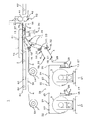
本発明の実施例1に係る光学フィルム貼付装置について図面を用いて説明する。図1は、本発明の実施例1に係る光学フィルム貼付装置の構成を模式的に示した正面図であり、図2は基板搬送系の上面図であり、図3はフィルム搬送系(剥離フィルムの巻取りについては省略)の上面図である。図4は、本発明の実施例1に係る光学フィルム貼付装置の制御部の構成を模式的に示したブロック図である。図5は、本発明の実施例1に係る光学フィルム貼付装置によって基板に貼り付けられた光学フィルムの貼付パターンを示した模式図である。
【0037】
この光学フィルム貼付装置1では、2つの巻出ロール3が1台の装置に掛けられており、巻き出された各帯状フィルム4から切り出された複数のフィルム片5、又は、複数の帯状フィルム4を1枚の(大型の)基板2の片側全面又は一部の面に貼り付ける。光学フィルム貼付装置1は、フィルム巻出部と、フィルム供給部と、フィルム貼付部と、剥離フィルム巻取部と、基板搬送部と、基板位置決部と、制御部と、に分けることができる。
【0038】
ここで、巻出ロール3は、光学フィルム上に粘着層を介して剥離フィルム6が貼着された帯状フィルム4(帯状フィルムの断面については図6参照)が巻回されたロールである(図1参照)。巻取ロール7は、帯状フィルム4(若しくはフィルム片5)から分離された剥離フィルム6を巻き取るロールである(図1参照)。なお、フィルム片5は、帯状フィルム4から切り出されたものである。
【0039】
フィルム巻出部は、巻出ユニット21と、パスローラ22と、エッジセンサ23と、接合台24と、パスローラ25と、ダンサーローラ26と、空圧ユニット27と、パスローラ28と、を有する(図1参照)。なお、ここではフィルム巻出部は2つあるが、どちらも構成が同様であるので、片側のフィルム巻出部について説明する。
【0040】
巻出ユニット21は、巻出ロール3を水平にして支持するとともに巻出ロール3から帯状フィルム4を巻き出すためのユニットであり、巻出ロール3を回転可能に支持する水平な軸部(図示せず)と、この軸部の回転に制動をかけるブレーキ部(図示せず)と、この軸部を軸方向にスライドさせるスライド部(図示せず)と、を有する(図1及び図3参照)。ブレーキ部により、巻出ロール3の過剰な巻き出しが防止される。ブレーキ部には、軸部に取り付けられた円板の外周をバンドで締め付けたバンドブレーキを用いている。また、スライド部のスライドを制御することにより、巻出ロール3の巻きズレ等による送出位置のバラツキを補正することができる。
【0041】
パスローラ22は、巻出ロール3から巻き出された帯状フィルム4の送り出し方向を変える、軸が水平なローラである(図1及び図3参照)。エッジセンサ23は、パスローラ22から送られてきた帯状フィルム4の幅方向の端面の位置を検出するためのセンサ(ここではフォトセンサ)である(図1及び図3参照)。
【0042】
接合台24は、巻出ロール3から帯状フィルム4が無くなったときに、旧帯状フィルムと、新巻出ロールからの新帯状フィルムとを接合するための台である(図1及び図3参照)。接合台24は、吸着機能(図示せず)と、スライド機構(図示せず)と、スライド機構に設置されるフィルムカットヘッド(図示せず)と、フィルムカットヘッドに設置されるテープ貼りユニット(図示せず)と、を有する。接合台24のフィルムカットヘッドが通過する中央部分には、樹脂系プレートが埋め込まれており、樹脂系プレートによってフィルムカットヘッドが保護される。フィルムカットヘッドの刃先は、等角の丸刃又はナイフ刃がセットされている。丸刃の場合は、回転させるものでも、固定するものでもよい。フィルムカットヘッドには、刃に付着したごみをブローする機能(図示せず)と、吹き飛ばされたごみを集塵する機能(図示せず)と、を有する。なお、接合台24は、装置のレイアウト上可能の場合は、フィルム巻出部ごとに個々に設けず、共通に使用してもよい。帯状フィルム4の接合は、以下のようにして行われる。まず、巻出ロール3の帯状フィルム4の残量を検知し、装置が停止した後、接合台24に帯状フィルム4を吸着させ、接合台24のフィルムカットヘッドを自動又は手動でスライドさせ、帯状フィルム4を切断する。その後、巻出ロール3を新しいものに載せ替え、新帯状フィルムを旧帯状フィルム4の末端側の端部にオーバーラップさせた状態で接合台24のフィルムカットヘッドを用いて切断し、接合台24のテープ貼りユニットにより新帯状フィルムと旧帯状フィルム4とが貼り合わせることで、接合される。
【0043】
パスローラ25は、接合台24を通過した帯状フィルム4の送り出し方向を変える、軸が水平なローラである(図1及び図3参照)。ダンサーローラ26は、軸が水平であり、巻出ロール3からフィードローラ33までの間の帯状フィルム4のテンションを一定に保つためのローラであり、空圧ユニット27に回転可能かつスライド可能に取り付けられている(図1及び図3参照)。空圧ユニット27は、フィルム送り出しを安定に保つために、エアーの圧力により、ダンサーローラ26の自重を補正した上で、ロール径の大小による送り追従性の変化を補正する(図1参照)。パスローラ28は、ダンサーローラ26を通過した帯状フィルム4の送り出し方向を変える、軸が水平なローラである(図1及び図3参照)。
【0044】
フィルム供給部は、 つば付ローラ31と、エッジセンサ32と、フィードローラ33と、テンション計34と、パスローラ35と、レーザーカッタ36と、エッジ部材37と、エッジセンサ38と、を有する(図1参照)。なお、ここではフィルム供給部は2つあるが、どちらも構成が同様であるので、片側のフィルム供給部について説明する。
【0045】
つば付ローラ31は、パスローラ28を通過した帯状フィルム4の送り出し方向を変える、両端にフィルム位置規制を行うつばを持つ、軸が水平なローラであり、ローラの軸方向にスライドするスライド部(図示せず)を有する(図1及び図3参照)。 つば付ローラ31は、スライド部のスライドが制御(制御方法については後述)されることで、フィルムエッジの位置補正を行い、フィルム搬送系の通り芯98A、98B(中心軸)、又は、隣り合うの帯状フィルム4の間隔が一定になるように補正し、結果として基板2に対する斜め貼り付けを防止する。エッジセンサ32は、つば付ローラ31から送られてきた帯状フィルム4の幅方向の端面の位置を検出するためのセンサ(ここではフォトセンサ)である(図1及び図3参照)。
【0046】
フィードローラ33は、 つば付ローラ31を通過した帯状フィルム4をレーザーカッタ36側へ搬送する、軸が水平なローラであり、帯状フィルム4を挟み込む2つのローラが並列に配されたものである(図1及び図3参照)。また、フィードローラ33は、フィルム片5の位置及び基板2の位置に応じて駆動制御(制御方法については後述)される。
【0047】
テンション計34は、フィードローラ33とフィードローラ52との間の剥離フィルム6にかかるテンションを測定する計測器である(図1及び図3参照)。
【0048】
パスローラ35は、フィードローラ33を通過した帯状フィルム4の送り出し方向を変える、軸が水平なローラである(図1及び図3参照)。
【0049】
レーザーカッタ36は、2軸ロボットにレーザー発振機本体または光学系を設置し、フィルム搬送スピードに合わせ搬送中のフィルムをフィルム端面に対して直角にハーフカット(剥離フィルムをカットしないで光学フィルム及び粘着層をカット)するように制御(制御方法については後述)される(図1参照)。これにより、装置を一定速度で稼動させた状態でも、フィルムを間欠送りせず連続送りして、帯状フィルム4を長手方向に直交する方向にハーフカットして、パターン貼り付けが可能である(貼付パターンについては図5参照)。
【0050】
エッジ部材37は、先端に丸みを帯びたエッジを備えた部材である(図1参照)。エッジ先端部をフィルム片5の進行方向に向け、一の刃面を剥離フィルム6表面に当接させ、エッジ先端部で剥離フィルム6のみが他の刃面側へ折り返されている。エッジ部材37の底面は水平に配されている。これにより、フィルム片5は、基板2と平行に送出され、圧着ローラ42の円弧上に乗り、ロール接線部分で基板2と接触する。エッジ部材37をこのように配置することにより、フィルム片5と基板2が接触する時の貼り付け位置のズレをなくし、フィルム片5を精度よく貼り付けることができる。
【0051】
エッジセンサ38は、剥離フィルム6が分離されたフィルム片5の前端側の端面を検出するためのセンサ(ここではフォトセンサ)である(図1参照)。
【0052】
フィルム貼付部は、受ローラ41と、圧着ローラ42と、バックアップローラ43と、を有する(図1参照)。なお、この実施例では、フィルム貼付部は、フィルム巻出部及びフィルム供給部と異なり1つであるが、フィルム巻出部及びフィルム供給部と同じ数を設けてもよいし、装置の長手方向と異なる位置に、独立して複数台のフィルム巻出部、フィルム供給部及びフィルム貼付部の組を設けてもよい。
【0053】
受ローラ41は、基板2をコンベア61側からコンベア62側へ搬送するとともに、下方側から圧着ローラ42の押圧力を受ける、軸が水平なローラである(図1参照)。また、受ローラ41は、フィルム片5の位置及び基板2の位置に応じて駆動制御(制御方法については後述)される。
【0054】
圧着ローラ42は、基板2の下面側から受ローラ41に向かって押圧することにより、並列に送出された複数のフィルム片5を巻き込んで基板2の下側板面に圧着させる、軸が水平なローラである(図1参照)。圧着ローラ42は、昇降機構(図示せず)に取り付けられている。昇降機構は、フィルム片5の位置及び基板2の位置に応じて、フィルム片5を基板2に貼合する際には上昇して受ローラ41側に押圧力をかけ、1つの基板2の貼付が終了して次の基板2の貼合の準備ができるまでの間は下降するよう制御(制御方法については後述)される。圧着ローラ42には、クラウンが設けられていない。
【0055】
バックアップローラ43は、圧着ローラ42をその下側から押圧する複数のニップローラであり、個々のニップローラは、貼付パターン(いくつかのパターンについて図5参照)に合わせて圧力可変が可能なものである(図1参照)。これにより、パターン貼り付けで微妙な圧力バランスをコントロールすることができる。
【0056】
剥離フィルム巻取部は、パスローラ51と、フィードローラ52と、パスローラ53と、巻取ユニット54と、を有する(図1参照)。なお、ここでは剥離フィルム巻取部は2つあるが、どちらも構成が同様であるので、片側の剥離フィルム巻取部について説明する。
【0057】
パスローラ51は、エッジ部材37で分離された剥離フィルム6の送り出し方向を変える、軸が水平なローラである(図1参照)。
【0058】
フィードローラ52は、剥離フィルム6を巻取ユニット54側へ搬送する、軸が水平なローラであり、剥離フィルム6を挟み込む2つのローラが並列(ローラ計4つ)に配されたものである(図1参照)。また、フィードローラ52は、フィルム片5の位置及び基板2の位置に応じて駆動制御(制御方法については後述)される。フィードローラ52とともにテンション計34を設け、テンションが狙った値になるようにフィードローラ52を制御することで、複数の帯状フィルム4若しくは剥離フィルム6を同時にフィードローラ33、レーザーカッタ36、エッジ部材37に掛けた場合にも、それぞれの帯状フィルム4若しくは剥離フィルム6を同一テンションに保て、帯状フィルム4若しくは剥離フィルム6に生ずる滑りや浮きを抑えることができ、各々動作が安定的に行える。フィードローラ52は同軸であるが、回転制御は独立動作が可能なものである。
【0059】
パスローラ53は、フィードローラ52から送出された剥離フィルム6の送り出し方向を変える、軸が水平なローラであり、フィードローラ52に近い方の巻取ユニット54と剥離フィルム6の抵触を防止するためのものである(図1参照)。
【0060】
巻取ユニット54は、巻取ロール7を回転駆動させて剥離フィルム6を巻き取るとともに、軸が水平な巻取り軸を有するユニットである(図1参照)。巻取ユニット54には、トルク発生器が備えられており、一定トルクで剥離フィルム6を巻き取る。巻取ユニット54は、巻取り軸の外径が可変可能なものであり、これにより巻き取った剥離フィルム6を外しやすくすることができる。巻取ユニット54は、フィルム片5の位置及び基板2の位置に応じて駆動制御される。
【0061】
基板搬送部は、コンベア61とコンベア62を有し、それぞれのコンベアには、駆動ホイール63と、補助ホイール64と、を有する(図2参照)。なお、基板搬送部は、フィルム巻出部及びフィルム供給部と異なり1つである。
【0062】
コンベア61は、フィルム片5が貼着されるべき基板2を水平かつ一定方向に搬送するホイールコンベアである(図2参照)。また、コンベア61(の駆動ホイール63)は、フィルム片5の位置及び基板2の位置に応じて駆動制御される。
【0063】
コンベア62は、圧着ローラ42と受ローラ41の間を通って複数のフィルム片5が貼合されて出てくる基板2を水平かつ一定方向に搬送するホイールコンベアである(図2参照)。また、コンベア62(の駆動ホイール63)は、フィルム片5の位置及び基板2の位置に応じて駆動制御され、コンベア61の動作と同期する。なお、必要であれはコンベア61における基板供給部若しくはコンベア62における基板排出部にロボットアーム等の方向変換機構を設置してもよい。
【0064】
駆動ホイール63は、コンベア61及びコンベア62に並べられた駆動制御(制御方法については後述)されるホイールであり、圧着ローラ42と受ローラ41の間にフィルム片5及び基板2を巻き込んだ後、下側に後退する(図2参照)。補助ホイール64は、コンベア61及びコンベア62に並べられた駆動されていないホイールである(図2参照)。
【0065】
基板位置決部は、ローラ72を持つ位置決ユニット71と、ローラ74を持つ位置決ユニット73と、ストッパ75と、エア吹出ユニット76と、を有する(図2参照)。なお、本実施例では、基板位置決部は、2台あるフィルム巻出部及びフィルム供給部と異なり1台ある。
【0066】
位置決ユニット71は、コンベア61上の基板2を背後側から押して進行方向の位置決めを行う機構である(図2参照)。ローラ72は、位置決ユニット71に取付けられ、基板2の端面に当接するローラである(図2参照)。
【0067】
位置決ユニット73は、コンベア61上の基板2を進行方向に対し直交する方向の両側から規制して進行方向に対し直交する方向の位置決めを行う機構である(図2参照)。また、位置決ユニット73は、エッジセンサ32によって得られた帯状フィルム4の位置に応じて自身の位置を合わせ、基板2の進行方向に対し直交する方向の位置の補正を行う。ローラ74は、位置決ユニット73に取付けられ、基板2の端面に当接するローラである(図2参照)。
【0068】
ストッパ75は、受ローラ41及び圧着ローラ42の近傍に配設され、基板2の移動を阻止する部材である(図2参照)。また、ストッパ75は、1つの基板2の貼付が終了して下流に送られた後に搬送ライン上に出てきて、コンベア61によって搬送されてきた次の基板2の端面がストッパ75に当接する。ストッパ75によって、基板2の搬送が阻止されるのと同時に、基板2の到着を制御部に知らせ、コンベア61の駆動を停止させる。ストッパ75は、位置決ユニット71及び位置決ユニット73によって基板2の位置決めがされた後、引っ込めて基板2の係止を解除する。
【0069】
エア吹出ユニット76は、基板2の位置決めの際、下側からエアを基板2に吹き付けるユニットであり、これにより、基板2を浮上させ、基板2の位置決めの際、基板2と駆動ホイール63又は補助ホイール64とが擦れないので、基板2へのキズの発生を防止することができる(図2参照)。
【0070】
制御部80は、少なくとも巻出ユニット21、エッジセンサ23、つば付ローラ31、エッジセンサ32、フィードローラ33、テンション計34、レーザーカッタ36、エッジセンサ38、受ローラ41、圧着ローラ42、フィードローラ52、駆動ホイール63、位置決ユニット71、位置決ユニット73、ストッパ75、エア吹出ユニット76のそれぞれと電気的に接続するコンピュータであり(図4参照)、所定のプログラム又はデータベースに基づいて、(1)巻出ロール3からの帯状フィルム4の送り出し位置に係る第1の制御(第1位置制御手段81による制御)と、(2)帯状フィルム4の通り芯98A、98B、及び複数の帯状フィルム4間の距離に係る第2の制御(第2位置制御手段82による制御)と、(3)剥離フィルム6の張りに係る第3の制御(張力制御手段83による制御)と、(4)フィルム片5の供給に係る第4の制御(送出制御手段84による制御)と、(5)基板2の搬送に係る第5の制御(搬送制御手段85による制御)と、(6)フィルム片5の貼付に係る第6の制御(貼付制御手段86による制御)と、が行われる。
【0071】
第1の制御では、第1位置制御手段81により、エッジセンサ23からの帯状フィルム4のエッジ位置に係る情報に基づいて、巻出ロール3の巻きズレ等による帯状フィルム4の送り出し位置のバラツキが生じないように、巻出ユニット21のスライド部のスライドを制御して、巻出ロール3の位置を補正する(図1、図3及び図4参照)。
【0072】
第2の制御では、第2位置制御手段82により、エッジセンサ32からの帯状フィルム4のエッジ位置に係る情報に基づいて、それぞれの帯状フィルム4の通り芯98A、98B及び複数の帯状フィルム4間の距離が一定になるよう、 つば付ローラ31のスライド部のスライドを制御し、結果として基板2に対する斜め貼り付けを防止する(図1、図3及び図4参照)。
【0073】
第3の制御では、張力制御手段83により、テンション計34からの帯状フィルム4のテンションに係る情報に基づいて、ハーフカット時、フィルム送出時、及びフィルム剥離時の剥離フィルム6のテンションが一定になるように、フィードローラ52の回転を制御する(図1及び図4参照)。
【0074】
第4の制御では、送出制御手段84により、基板2に貼り付けるパターンにより設定された帯状フィルム4の送り量及び切断タイミングに係る情報に基づいて、フィードローラ33及びフィードローラ52の回転量と、レーザーカッタ36の切断タイミングと、を制御し、基板2への断続的なパターン貼りを可能にする(図1及び図4参照)。なお、断続的なパターン貼りの必要がない場合は、貼付パターンにより受ローラ41及び圧着ローラ42の間欠動作に合わせて、帯状フィルム4を間欠送りするように、フィードローラ33及びフィードローラ52の回転量と、レーザーカッタ36の切断タイミングと、を制御する。
【0075】
第5の制御では、搬送制御手段85により、コンベア61上で搬送される基板2がストッパ75に当接することにより搬送を停止させ、エア吹出ユニット76からエアを吹き出して基板2を浮上させ、位置決ユニット71に基板2の進行方向の位置決めを行わせ、エッジセンサ32からの帯状フィルム4のエッジ位置に係る情報に基づいて、位置決ユニット73に基板2の進行方向に対し直交する方向の位置決めを行わせるように制御する(図2参照)。位置決め完了後、ストッパ75を解除させ、ローラ駆動で基板2を送り出させ、受ローラ41と圧着ローラ42の間にフィルム片5及び基板2を巻き込んだ後に、駆動ホイール63を下側に後退させるように制御する(図1、図2及び図4参照)。
【0076】
第6の制御では、貼付制御手段86により、エッジセンサ38からのフィルム片5の前端検出位置まで送ったという情報と、基板2の位置決めが完了したという情報と、をトリガーとして、装置を運転を開始し、基板2とフィルム片5を同時に送り出すように制御する(図1、図3及び図4参照)。次に、受ローラ41と圧着ローラ42の間にフィルム片5(若しくは帯状フィルム4)と基板2が挟み込まれ、駆動ホイール63が下側に後退したときに、順次フィルムを送り、パターン貼り付けするように制御する。なお、基板2とフィルム片5を貼付するスタート位置は、フィルム先端の端部でなくてもよい。この場合、フィルム片5及び基板2の先端位置決めのためのエッジセンサ38を受ローラ41及び圧着ローラ42よりも下流側に設定し、貼付をフィルムの端部でなく中央でまず行う。その後、受ローラ41及び圧着ローラ42を逆転させ、フィルム片5及び基板2を上流側へ戻しながら、受ローラ41及び圧着ローラ42よりも下流側の部分を貼付した後、受ローラ41及び圧着ローラ42を正転させ、フィルム片5及び基板2の残りの部分を貼付する。
【0077】
次に、本発明の実施例1に係る光学フィルム貼付装置の動作について説明する。
【0078】
まず、各帯状フィルム4は、各巻出ロール3からフィルムエッジ位置が補正されながらフィードローラ33に引き出されて、巻き出され、ダンサーローラ26によってテンションが調整されながら繰り出される(図1参照)。
【0079】
次に、送り出された各帯状フィルム4は、 つば付ローラ31によってフィルムエッジ位置の補正が行われながら搬送され、フィードローラ52によって剥離フィルム6のテンションが調整されながら搬送される(図1参照)。搬送される各帯状フィルム4は、所定の同じ長さ又は異なる長さまで進行したときに、フィルムの長手方向に対し直交する方向にハーフカット(剥離フィルム6を残してその他の部分をカット)される。なお、帯状フィルム4は、貼り付けられるフィルム片5の長さと、レーザーカッタ36と圧着ローラ42間の距離との関係で、ハーフカットされる前に剥離フィルム6を分離して基板2に貼り付けられる場合もあるが、この場合は、帯状フィルム4を基板2に貼り付けている途中でハーフカットする。
【0080】
次に、ハーフカットにより切り出された各フィルム片5(又はハーフカットされていない一方又は両方の帯状フィルム4)は、エッジ部材37によって剥離フィルム6のみが分離される(図1参照)。分離された各剥離フィルム6は、フィードローラ52によって送出され、各巻取ロール7に巻き取られることになる。
【0081】
次に、剥離フィルム6が分離された各フィルム片5(又はハーフカットされていない一方又は両方の帯状フィルム4)は、コンベア61上で位置決めされた基板2の貼付位置(フィルム片5の幅方向の端面が互いに平行で、フィルム片5の切断面と基板2の長手方向側の端面とが互いに平行になる当該基板2の対応する位置)に合わせて、受ローラ41と圧着ローラ42の間を通る基板2下面と圧着ローラ42の間に接着面を基板2側に向けて供給され、圧着ローラ42の押圧力により基板2に貼り付けされつつコンベア62側に搬送される(図1参照)。受ローラ41と圧着ローラ42の間を通過した基板2は、その下面側に複数のフィルム片5が貼り付けられた状態となってコンベア62によって搬送されることとなる。
【0082】
次に、その他の実施例について説明する。
【0083】
実施例2として、実施例1(図1参照)におけるコンベア62の所定の位置にカメラ(図示せず)を配設する。基板2に貼り付けられたフィルム片5の貼付位置を前記カメラで撮影し、前記カメラで撮影された画像情報を処理する。これにより、フィルム片5の貼付位置を検査することができる。
【0084】
実施例3として、実施例1(図1参照)において帯状フィルム4と摩擦が生じやすいフィードローラ33、エッジ部材37、受ローラ41、圧着ローラ42等の構成部の近傍に、静電気を除去する除電装置(図示せず)を設ける。これにより、フィルム片5の貼付直前に、フィルム片5が基板2に付着するのを防止することができる。
【0085】
実施例4として、実施例1(図1参照)の光学フィルム貼付装置1の所定の位置にクリーンファン(図示せず)や集塵装置(図示せず)を設ける。これにより、クリーンな環境で装置を稼動させることができ、フィルム片5と基板2の間にゴミが挟み込まれるのを抑えることができる。
【0086】
実施例5として、フィルムを個別に間欠送りしてのパターン貼りをしない場合は、実施例1(図1参照)における2つのフィルム供給系を1つにし、フィルム巻出部のみ独立させ複数のフィルムを同時に送り出すようにする。フィルム巻出部に干渉(若しくは抵触)がある場合は、フィルム巻出部を左右方向、前後方向、または上下方向に配置してよい。左右方向に間隔をおいて配置した場合は、パスローラ25とダンサーローラ26の間に傾斜ローラ(図示せず)を設け、ダンサーローラ26部分で帯状フィルム4を水平かつ平行にする。
【0087】
実施例6として、フィルム供給系から貼付手段まで2個持つものがある。この場合、図7及び図8に示すように基板2に光学フィルム片5を貼り付ける位置が前後に位置し、2個の貼付手段14は中間にコンベア62、61´を介してシリーズにつながる。
【0088】
【発明の効果】
本発明によれば、基板が大型になっても、従来幅のフィルムロールで基板全面を一度に貼り付けることができる。
【0089】
また、本発明によれば、複数の光学フィルムを同じ条件(圧力、テンション等)で貼り付けられるので、シワ等がなく貼り付けることができる。
【0090】
また、本発明によれば、無駄な領域に光学フィルムを貼り付けなくてすむので、光学フィルムの無駄をなくすことができ、後工程での額縁剥ぎ取り工程をなくすことができる。その結果、フィルム裁断時のあまり幅品を有効に活用することができる。
【0091】
また、本発明によれば、機能の異なる光学フィルムを同時に貼り付けることができる。
【0092】
また、本発明によれば、幅広で寸法や重量の大きいフィルムを扱わずにすむので、前工程での搬送送り出し、通紙の作業性がよく、それらの装置も小型ですみ、フレキシブルなレイアウト設計が可能となる。
【0093】
さらに、本発明によれば、基板の広幅化に対応する光学フィルムの製造工程を新規に製作する大型設備投資をなくすことができ、新規に製造工程を製作した場合、品質造り込み難易度アップによる得率ダウンを回避することができる。
【図面の簡単な説明】
【図1】本発明の実施例1に係る光学フィルム貼付装置の構成を模式的に示した正面図である。
【図2】本発明の実施例1に係る光学フィルム貼付装置の基板搬送系の構成を模式的に示した上面図である。
【図3】本発明の実施例1に係る光学フィルム貼付装置のフィルム搬送系の構成を模式的に示した上面図である。
【図4】本発明の実施例1に係る光学フィルム貼付装置の制御部の構成を模式的に示したブロック図である。
【図5】本発明の実施例1に係る光学フィルム貼付装置によって基板に貼り付けられた光学フィルムの貼付パターンを示した模式図である。
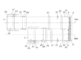
【図6】本発明の実施例1に係る光学フィルム貼付装置において用いられる帯状フィルムの構成を模式的に示した断面図である。
【図7】本発明の実施例6に係る光学フィルム貼付装置の構成を模式的に示した正面図である。
【図8】本発明の実施例6に係る光学フィルム貼付装置のフィルム搬送系の構成を模式的に示した上面図である。
【符号の説明】
1 光学フィルム貼付装置
2 基板
3 巻出ロール
4 帯状フィルム
5 フィルム片
6 剥離フィルム
7 巻取ロール
11 帯状フィルム送出手段
12 切断手段
13 剥離フィルム分離手段
14 貼付手段
15 張力調整手段
16 剥離フィルム送出手段
17 張力検出手段
18 位置検出手段
19 位置補正手段
21 巻出ユニット
22 パスローラ
23 エッジセンサ
24 接合台
25 パスローラ
26 ダンサーローラ
27 空圧ユニット
28 パスローラ
31 つば付ローラ
32 エッジセンサ
33 フィードローラ
34 テンション計
35 パスローラ
36 レーザーカッタ
37 エッジ部材
38 エッジセンサ
41 受ローラ
42 圧着ローラ
43 バックアップローラ
51 パスローラ
52 フィードローラ
53 パスローラ
54 巻取ユニット
61、61´ コンベア
62、62´ コンベア
63 駆動ホイール
64 補助ホイール
71 位置決ユニット
72 ローラ
73 位置決ユニット
74 ローラ
75 ストッパ
76 エア吹出ユニット
80 制御部
81 第1位置制御手段
82 第2位置制御手段
83 張力制御手段
84 送出制御手段
85 搬送制御手段
86 貼付制御手段
91、93 粘着層
92 位相差膜(光学フィルム)
94、96 保護フィルム
95 偏光板(光学フィルム)
97 合紙
98A、98B 通り芯[0001]
BACKGROUND OF THE INVENTION
The present invention relates to an optical film attaching apparatus and method for attaching an optical film such as a deflector plate or a retardation film to a substrate such as a liquid crystal display or a plasma display. It is related with the optical film sticking apparatus, method, and board | substrate which make it possible to paste.
[0002]
[Prior art]
As a method of attaching an optical film such as a deflector plate or a retardation film to a display substrate such as a liquid crystal display or a plasma display, a method of attaching a film piece obtained by punching a roll-shaped optical film in advance to a substrate (for example, , Patent Document 1) and a method of cutting an optical film after bonding a roll-shaped optical film (for example, see Patent Document 2) are known.
[0003]
[Patent Document 1]
JP 2002-23151 A
[Patent Document 2]
Japanese Patent Laid-Open No. 11-95028
[0004]
[Problems to be solved by the invention]
In recent years, the size of display substrates has been increasing. However, when an optical film is attached to the entire surface of a display substrate, the width of a conventional optical film or film piece cannot be adapted to the size of the display substrate. In order to solve such problems, it may be necessary to manufacture a wide optical film that can accommodate the size of the display substrate, but this requires the introduction of a new manufacturing process, which requires a great deal of investment. However, there is a problem that the manufacturing difficulty is high and the yield is poor.
[0005]
In addition, when a wide optical film or film piece that can accommodate the size of the large display substrate is bonded to the large display substrate, the technical difficulty such as uniform application, prevention of wrinkles, and tension control is high, and the yield is high. There is a problem of being bad.
[0006]
A first object of the present invention is to provide an optical film sticking apparatus and method that make it possible to stick a film to the entire surface of a large display substrate even with a narrow optical film.
[0007]
The second object of the present invention is to provide an optical film sticking apparatus and method capable of uniformly sticking an optical film, preventing wrinkles, and controlling tension.
[0008]
The 3rd objective of this invention is to provide the board | substrate which bonded the optical film on the whole surface on the large sized board | substrate using the optical film with a narrow width | variety.
[0009]
The 4th object of this invention is to provide the board | substrate which reduced the film loss by not bonding an optical film to the part which does not need to be bonded in a large sized board | substrate.
[0010]
[Means for Solving the Problems]
In the 1st viewpoint of this invention, in an optical film sticking apparatus (1) which sticks an optical film (film piece 5) to a board | substrate (2), a peeling film (6) is stuck on an optical film through an adhesion layer. WornAnd placed in parallelMultiple strip films (4) in the longitudinal directionSent toThe strip-shaped film delivery means (11) to be taken out and each of the fed strip-shaped film (4) are cut in a direction orthogonal to the longitudinal direction at least the optical film and the adhesive layer, leaving the release film (6). Cutting means (12) to perform, each film piece (5) cut by cutting, or release film separating means (13) to separate the release film (6) from each of the strip-like film (4), The adhesive surface of each film piece (5) or strip film (4) from which the release film (6) has been separated is the end face in the width direction of each film piece (5) or strip film (4). And one or a plurality of attaching means (14) for attaching to a plate surface on one side of the substrate (2) so that they are parallel to each other.
[0011]
In a second aspect of the present invention, in an optical film attaching method for attaching an optical film to a substrate, a plurality of strip-like films each having a release film attached to the optical film via an adhesive layer are sent in the longitudinal direction. A step of cutting each of the fed film-like films in a direction perpendicular to the longitudinal direction of at least the optical film and the adhesive layer, leaving the release film, and each film cut out by cutting A step of separating the release film from the piece or the strip-shaped film, and an end surface in the width direction of each of the film pieces or the strip-shaped film from which the release film is separatedEach otherAnd a step of affixing to the plate surface on one side of the substrate simultaneously or separately so as to be parallel to each other.
[0012]
Thereby, a film can be affixed on the whole large display substrate of a wide width with a narrow width optical film.
[0013]
Moreover, in the said optical film sticking apparatus (1) of this invention, the several tension | tensile_strength which adjusts each tension | tensile_strength of the some strip | belt-shaped film (4) by which the peeling film (6) was stuck via the adhesion layer on the optical film. It is preferable that an adjusting means (15) is provided, and the belt-shaped film sending means (11) feeds the belt-like film (4) whose tension is adjusted by the tension adjusting means (15). Moreover, in the optical film sticking method of the present invention, it is preferable that the tension of each of the belt-like films is adjusted independently for each of the belt-like films before the step of feeding the belt-like film. Thereby, the optical film of the narrow width | variety number can be affixed on a same condition uniformly without wrinkles.
[0014]
Moreover, in the said optical film sticking apparatus (1) of this invention, the said strip | belt-shaped film sending means (11) sends out independently for every said strip | belt-shaped film (4), and for every said separated said peeling film (6) Independently, a plurality of release film delivery means (16) for delivering the release film (6) from the release film separating means (13) to the outside, the strip-like film delivery means (11), and the cutting means (12) ) Between the plurality of tension detecting means (17) for detecting the tension of the belt-like film (4) for each of the belt-like films (4) and the information on the tension from the tension detecting means (17). Then, at least one of the strip film sending means (11) and the release film sending means (16) is controlled so that the tension of each of the strip films (4) becomes a predetermined value. It is preferable to provide the force control means (83), the. Further, in the optical film sticking method of the present invention, when the belt-like film is sent out, the belt-like film is sent out independently for each strip-like film, and is separated from the release film separating means independently for each separated release film. Sending the release film separately to the outside, detecting the tension of the belt-like film for each of the belt-like films between the feeding step and the cutting step of the belt-like film, and based on the information relating to the detected tension, It is preferable to control at least one of the feeding of the strip-shaped film and the feeding of the release film so that the tension of the strip-shaped film becomes a predetermined value. Thereby, the optical film of the narrow width | variety number can be affixed on a same condition uniformly without wrinkles.
[0015]
Moreover, in the optical film sticking apparatus (1) of the present invention, the belt-shaped film sending means (11) feeds the belt-like film (4) independently, and the cutting means (12) is the belt-like film. (4) At least the strip film sending means (11) and the cutting means (4) so that the strip films (4) are cut independently and sent to the same length or different lengths in the longitudinal direction for each strip film (4). It is preferable to provide a delivery control means (84) for controlling 12). Further, in the optical film sticking method of the present invention, when sending the strip film, it is sent independently for each strip film, and when cutting the strip film, it is cut independently for each strip film, It is preferable to control the feeding and cutting of the strip film so that the strip film is fed to the same length or different lengths in the longitudinal direction. Thereby, an optical film can be affixed to a large substrate without waste in the longitudinal direction (film traveling direction) according to a required pattern.
[0016]
Moreover, in the said optical film sticking apparatus (1) of this invention, several position detection means (18) which detects the position of the edge part of the at least one side of the width direction of the said strip | belt-shaped film (4) for every said strip | belt-shaped film (4). ), A plurality of position correcting means (19) capable of correcting the belt-like film (4) in the width direction for each of the belt-like films (4), and a position from the position detecting means (18). Position control means (second position control means 82) for controlling the position correction means (19) so that the position in the width direction of each of the strip films (4) is constant based on the information. It is preferable. Further, in the optical film sticking method of the present invention, the position of at least one end in the width direction of the belt-like film is detected for each belt-like film, and each belt-like film is detected based on information on the detected position. It is preferable to correct the strip film in the width direction for each strip film so that the position in the width direction is constant. Thereby, an optical film can be affixed to a large substrate without waste in the lateral direction (film width direction) according to a required pattern.
[0017]
According to the optical film sticking apparatus and the optical film sticking method of the present invention, for example, a substrate on which an optical film piece is stuck in a form as shown in FIG. 5 can be obtained..
[0020]
It should be noted that the reference numerals attached to the drawings described above are only for helping understanding of the invention, and are not limited to the embodiments described in the drawings.
[0021]
DETAILED DESCRIPTION OF THE INVENTION
An optical film sticking apparatus according to an embodiment of the present invention will be described. Referring to FIGS. 1 and 4, this optical
[0022]
Here, the belt-like film 4 is a belt-like film in which the
[0023]
The
[0024]
The belt-shaped film delivery means 11 is a means for delivering a plurality of belt-like films 4 in the longitudinal direction, and sends the belt-like film 4 unwound independently for each belt-like film 4 to the cutting means 12 side (see FIG. 1). ). Here, two
[0025]
The cutting means 12 has at least the optical film (layers 92 to 97 in FIG. 6) and the adhesive layer 91 orthogonal to the longitudinal direction, leaving the
[0026]
The release film separating means 13 is a means for separating the
[0027]
The sticking means 14 is formed on the
[0028]
The tension adjusting means 15 is a means for adjusting the tension of each strip film 4 independently for each strip film 4 before passing through the strip film sending means 11, and here, the
[0029]
The release film sending means 16 is means for sending the
[0030]
The tension detecting means 17 is a means for detecting the tension of the belt-like film 4 for each belt-like film 4 between the belt-like film sending means 11 and the cutting means 12, and here, a known
[0031]
The position detection means 18 is a means for detecting the position of at least one end in the width direction of the belt-like film 4 for each belt-like film 4. Here, a known edge sensor 32 (photoelectronic or optical photosensor) is used. Although used (see FIG. 1), a sound wave type or air type edge sensor may be used. The required number of
[0032]
The position correction means 19 is a means capable of correcting the belt-like film 4 in the width direction for each belt-like film 4. Here, the collar-attached
[0033]
The tension control means 83 is a controller or computer that controls the release film sending means 16 based on the information related to the tension from the tension detection means 17 so that the tension of each strip film 4 becomes a predetermined value (see FIG. 1 and FIG. 4).
[0034]
The delivery control means 84 is a controller that controls at least the belt-like film delivery means 11, the cutting means 12, and the release film delivery means 16 so as to feed each belt-like film 4 to the same length or different lengths in the longitudinal direction. A computer (see FIGS. 1 and 4).
[0035]
The position control means (second position control means 82) controls the position correction means 19 so that the position in the width direction of each belt-like film 4 is constant based on the information related to the position from the position detection means 18. Controller or computer (see FIGS. 1 and 4). Thereby, the diagonal sticking of the
[0036]
【Example】
An optical film sticking apparatus according to Example 1 of the present invention will be described with reference to the drawings. 1 is a front view schematically showing a configuration of an optical film sticking apparatus according to Example 1 of the present invention, FIG. 2 is a top view of a substrate transport system, and FIG. 3 is a film transport system (release film). Is omitted). FIG. 4 is a block diagram schematically illustrating the configuration of the control unit of the optical film sticking device according to the first embodiment of the present invention. FIG. 5 is a schematic diagram showing an optical film sticking pattern attached to a substrate by the optical film sticking apparatus according to Example 1 of the present invention.
[0037]
In this optical
[0038]
Here, the unwinding roll 3 is a roll in which a belt-like film 4 (see FIG. 6 for the cross section of the belt-like film) in which a
[0039]
The film unwinding section includes an unwinding
[0040]
The unwinding
[0041]
The
[0042]
The joining
[0043]
The
[0044]
The film supply unit includes a
[0045]
The
[0046]
The
[0047]
The
[0048]
The
[0049]
The
[0050]
The
[0051]
The
[0052]
The film sticking unit includes a receiving
[0053]
The receiving
[0054]
The
[0055]
The
[0056]
The release film winding unit includes a
[0057]
The
[0058]
The
[0059]
The
[0060]
The winding
[0061]
The substrate transport unit includes a
[0062]
The
[0063]
The
[0064]
The
[0065]
The substrate positioning unit includes a
[0066]
The
[0067]
The
[0068]
The
[0069]
The
[0070]
The control unit 80 includes at least an unwinding
[0071]
In the first control, the first position control unit 81 causes variations in the feeding position of the belt-like film 4 due to the winding deviation of the winding roll 3 based on the information related to the edge position of the belt-like film 4 from the
[0072]
In the second control, the second position control means 82 uses the information about the edge position of the strip film 4 from the
[0073]
In the third control, the tension control means 83 makes the tension of the
[0074]
In the fourth control, the amount of rotation of the
[0075]
In the fifth control, the conveyance control means 85 stops the conveyance when the
[0076]
In the sixth control, the operation of the apparatus is triggered by the information that the sticking control means 86 has sent the
[0077]
Next, operation | movement of the optical film sticking apparatus which concerns on Example 1 of this invention is demonstrated.
[0078]
First, each belt-like film 4 is drawn out from each unwinding roll 3 to the
[0079]
Next, each fed-out film 4 is conveyed while the film edge position is corrected by the
[0080]
Next, only the
[0081]
Next, each
[0082]
Next, other embodiments will be described.
[0083]
As Example 2, a camera (not shown) is disposed at a predetermined position of the
[0084]
As Example 3, static elimination is performed in the vicinity of components such as the
[0085]
As Example 4, a clean fan (not shown) and a dust collector (not shown) are provided at predetermined positions of the optical
[0086]
As Example 5, when not performing pattern pasting by intermittently feeding the films individually, the two film supply systems in Example 1 (see FIG. 1) are made one, and only the film unwinding part is made independent, and a plurality of films At the same time. When there is interference (or conflict) in the film unwinding part, the film unwinding part may be arranged in the left-right direction, the front-rear direction, or the up-down direction. When arranged in the left-right direction at intervals, an inclined roller (not shown) is provided between the
[0087]
As Example 6, there is one having two from the film supply system to the pasting means. In this case, as shown in FIG. 7 and FIG. 8, the position where the
[0088]
【The invention's effect】
According to this invention, even if a board | substrate becomes large sized, the whole board | substrate surface can be affixed at once with the film roll of the conventional width.
[0089]
Further, according to the present invention, since a plurality of optical films can be attached under the same conditions (pressure, tension, etc.), they can be attached without wrinkles or the like.
[0090]
In addition, according to the present invention, it is not necessary to attach the optical film to a useless area, so that the use of the optical film can be eliminated and the frame stripping process in the subsequent process can be eliminated. As a result, it is possible to effectively use a very wide product during film cutting.
[0091]
Moreover, according to this invention, the optical film from which a function differs can be affixed simultaneously.
[0092]
In addition, according to the present invention, since it is not necessary to handle a wide and heavy film with a large size and weight, work feeding and feeding in the previous process is easy, and these devices are small in size, and flexible layout design Is possible.
[0093]
Furthermore, according to the present invention, it is possible to eliminate the large-scale capital investment for newly manufacturing the optical film manufacturing process corresponding to the widening of the substrate, and when the manufacturing process is newly manufactured, it is possible to increase the difficulty in building quality. The yield can be avoided.
[Brief description of the drawings]
FIG. 1 is a front view schematically showing a configuration of an optical film sticking apparatus according to a first embodiment of the present invention.
FIG. 2 is a top view schematically showing a configuration of a substrate transport system of the optical film sticking apparatus according to
FIG. 3 is a top view schematically showing a configuration of a film transport system of the optical film sticking apparatus according to the first embodiment of the present invention.
FIG. 4 is a block diagram schematically showing a configuration of a control unit of the optical film sticking device according to the first embodiment of the present invention.
FIG. 5 is a schematic view showing a sticking pattern of an optical film attached to a substrate by the optical film sticking apparatus according to Example 1 of the present invention.
FIG. 6 is a cross-sectional view schematically showing the configuration of a belt-like film used in the optical film sticking apparatus according to Example 1 of the present invention.
FIG. 7 is a front view schematically showing a configuration of an optical film sticking apparatus according to Example 6 of the present invention.
FIG. 8 is a top view schematically showing the configuration of a film transport system of an optical film sticking apparatus according to
[Explanation of symbols]
1 Optical film sticking device
2 Substrate
3 Unwinding roll
4 Strip film
5 Film pieces
6 Release film
7 Winding roll
11 Strip film delivery means
12 Cutting means
13 Peeling film separating means
14 Affixing means
15 Tension adjusting means
16 Release film delivery means
17 Tension detection means
18 Position detection means
19 Position correction means
21 Unwinding unit
22 Pass Roller
23 Edge sensor
24 Joining table
25 pass rollers
26 Dancer Laura
27 Pneumatic unit
28 Pass Roller
31 Roller with collar
32 Edge sensor
33 Feed roller
34 Tension meter
35 Pass Roller
36 Laser cutter
37 Edge member
38 Edge sensor
41 Receiving roller
42 Pressure roller
43 Backup Roller
51 Pass Roller
52 Feed Roller
53 Pass Roller
54 Winding unit
61, 61 'conveyor
62, 62 'conveyor
63 Drive wheel
64 Auxiliary wheel
71 Positioning unit
72 Laura
73 Positioning unit
74 Laura
75 stopper
76 Air blowing unit
80 Control unit
81 First position control means
82 Second position control means
83 Tension control means
84 Sending control means
85 Transport control means
86 Sticking control means
91, 93 Adhesive layer
92 Retardation film (optical film)
94, 96 Protective film
95 Polarizing plate (optical film)
97 slip
98A, 98B Street core
Claims (10)
送出されたそれぞれの前記帯状フィルムを前記剥離フィルムを残して少なくとも前記光学フィルム及び前記粘着層を長手方向に対し直交する方向に切断する切断手段と、
切断により切り出されたそれぞれのフィルム片、又は、それぞれの前記帯状フィルムから前記剥離フィルムを分離する剥離フィルム分離手段と、
前記剥離フィルムが分離されたそれぞれの前記フィルム片又は前記帯状フィルムの粘着面を、それぞれの前記フィルム片又は前記帯状フィルムの幅方向の端面が互いに平行になるように、基板の片側の板面に貼り付ける1又は複数の貼付手段と、
を備えることを特徴とする光学フィルム貼付装置。A strip film feeding means for exiting feed release film through the adhesive layer on the optical film is adhered Rutotomoni, a plurality of strip-shaped film disposed in parallel in the longitudinal direction,
Cutting means for cutting each of the fed film-like films at least in the direction perpendicular to the longitudinal direction of the optical film and the adhesive layer, leaving the release film;
Each film piece cut out by cutting, or a release film separating means for separating the release film from each of the belt-like films,
The adhesive surface of each film piece or strip-like film from which the release film is separated is placed on the plate surface on one side of the substrate so that the end faces in the width direction of the respective film pieces or strip-like film are parallel to each other. One or more pasting means for pasting;
An optical film sticking device comprising:
前記帯状フィルム送出手段は、前記張力調整手段によって張力が調整されたそれぞれの前記帯状フィルムを送出することを特徴とする請求項1記載の光学フィルム貼付装置。Provided with a plurality of tension adjusting means for adjusting the tension of each of a plurality of strip-like films having a release film stuck on the optical film via an adhesive layer,
2. The optical film sticking apparatus according to claim 1, wherein the belt-shaped film sending means feeds the belt-like film whose tension is adjusted by the tension adjusting means.
分離された前記剥離フィルムごとに独立して、前記剥離フィルム分離手段からその外部に前記剥離フィルムを送出する複数の剥離フィルム送出手段と、
前記帯状フィルム送出手段と前記切断手段の間で、前記帯状フィルムごとに前記帯状フィルムの張力を検出する複数の張力検出手段と、
前記張力検出手段からの張力に係る情報に基づいて、それぞれの前記帯状フィルムの張力が所定値となるように、前記帯状フィルム送出手段及び前記剥離フィルム送出手段の少なくとも一方を制御する張力制御手段と、
を備えることを特徴とする請求項1又は2記載の光学フィルム貼付装置。The belt-like film sending means sends each belt-like film independently,
A plurality of release film sending means for sending the release film to the outside from the release film separating means independently for each of the separated release films;
A plurality of tension detecting means for detecting the tension of the belt-like film for each of the belt-like films between the belt-like film sending means and the cutting means;
Tension control means for controlling at least one of the strip film sending means and the release film sending means so that the tension of each of the strip films becomes a predetermined value based on the information on the tension from the tension detecting means. ,
The optical film sticking device according to claim 1, comprising:
前記切断手段は、前記帯状フィルムごとに独立して切断し、
前記帯状フィルムごとにその長手方向に同じ長さ若しくは異なる長さに送出するように、少なくとも前記帯状フィルム送出手段及び前記切断手段を制御する送出制御手段を備えることを特徴とする請求項1乃至3のいずれか一項に記載の光学フィルム貼付装置。The belt-like film sending means sends each belt-like film independently,
The cutting means cuts independently for each of the belt-like films,
4. A feed control means for controlling at least the strip film sending means and the cutting means so as to feed the strip films to the same length or different lengths in the longitudinal direction thereof. The optical film sticking apparatus as described in any one of these.
前記帯状フィルムごとに前記帯状フィルムをその幅方向に補正させることが可能な複数の位置補正手段と、
前記位置検出手段からの位置に係る情報に基づいて、前記帯状フィルムごとにその幅方向の位置が一定となるように、前記位置補正手段を制御する位置制御手段と、
を備えることを特徴とする請求項1乃至4のいずれか一項に記載の光学フィルム貼付装置。A plurality of position detection means for detecting the position of at least one end of the strip film in the width direction for each strip film;
A plurality of position correcting means capable of correcting the strip film in the width direction for each strip film;
Based on the information related to the position from the position detection means, a position control means for controlling the position correction means so that the position in the width direction is constant for each of the belt-like films,
The optical film sticking device according to any one of claims 1 to 4, further comprising:
送出されたそれぞれの前記帯状フィルムを、前記剥離フィルムを残して少なくとも前記光学フィルム及び前記粘着層を長手方向に対し直交する方向に、切断するステップと、
切断により切り出されたそれぞれのフィルム片、又は、それぞれの前記帯状フィルムから前記剥離フィルムを分離するステップと、
前記剥離フィルムが分離されたそれぞれの前記フィルム片又は前記帯状フィルムの粘着面を、それぞれの前記フィルム片又は前記帯状フィルムの幅方向の端面が互いに平行になるように、前記基板の片側の板面に同時又は別々に貼り付けるステップと、
を含むことを特徴とする光学フィルム貼付方法。A step of sending a plurality of strip-like films in which a release film is stuck on an optical film via an adhesive layer in the longitudinal direction;
Cutting each of the fed film-like films in a direction orthogonal to the longitudinal direction, at least the optical film and the adhesive layer, leaving the release film;
Separating the release film from each piece of film cut by cutting or from each of the strip-shaped films;
The plate surface on one side of the substrate so that the adhesive surfaces of the film pieces or strip films separated from the release film are parallel to each other in the width direction of the film pieces or strip films. A step of applying to or simultaneously to,
The optical film sticking method characterized by including.
分離された前記剥離フィルムごとに独立して、前記剥離フィルム分離手段からその外部に前記剥離フィルムを別々に送出し、
前記帯状フィルムを送出するステップと切断するステップの間で、前記帯状フィルムごとに前記帯状フィルムの張力を検出し、
検出した張力に係る情報に基づいて、それぞれの前記帯状フィルムの張力が所定値となるように、前記帯状フィルムの送出及び前記剥離フィルムの送出の少なくとも一方を制御することを特徴とする請求項6又は7記載の光学フィルム貼付方法。When sending the band-like film, send it independently for each band-like film,
Independently for each of the separated release films, the release film is sent separately from the release film separating means to the outside,
Between the step of feeding and cutting the strip film, the tension of the strip film is detected for each strip film,
7. At least one of feeding of the belt-like film and feeding of the release film is controlled based on information on the detected tension so that the tension of each strip-like film becomes a predetermined value. Or the optical film sticking method of 7.
前記帯状フィルムを切断する際、前記帯状フィルムごとに独立して切断し、
前記帯状フィルムごとにその長手方向に同じ長さ若しくは異なる長さに送出するように、前記帯状フィルムの送出及び切断を制御することを特徴とする請求項6乃至8のいずれか一項に記載の光学フィルム貼付方法。When sending the band-like film, send it independently for each band-like film,
When cutting the strip film, cut independently for each strip film,
The feeding and cutting of the strip film are controlled so that the strip films are fed to the same length or different lengths in the longitudinal direction. Optical film sticking method.
検出した位置に係る情報に基づいて、前記帯状フィルムごとにその幅方向の位置が一定となるように、前記帯状フィルムごとに前記帯状フィルムをその幅方向に補正することを特徴とする請求項6乃至9のいずれか一項に記載の光学フィルム貼付方法。Detect the position of at least one end in the width direction of the strip film for each strip film,
7. The belt-like film is corrected in the width direction for each of the belt-like films so that the position in the width direction is constant for each of the belt-like films based on information relating to the detected position. The optical film sticking method as described in any one of thru | or 9.
Priority Applications (1)
| Application Number | Priority Date | Filing Date | Title |
|---|---|---|---|
| JP2003126592A JP4342829B2 (en) | 2003-05-01 | 2003-05-01 | Optical film sticking device, method and substrate |
Applications Claiming Priority (1)
| Application Number | Priority Date | Filing Date | Title |
|---|---|---|---|
| JP2003126592A JP4342829B2 (en) | 2003-05-01 | 2003-05-01 | Optical film sticking device, method and substrate |
Publications (2)
| Publication Number | Publication Date |
|---|---|
| JP2004333647A JP2004333647A (en) | 2004-11-25 |
| JP4342829B2 true JP4342829B2 (en) | 2009-10-14 |
Family
ID=33503474
Family Applications (1)
| Application Number | Title | Priority Date | Filing Date |
|---|---|---|---|
| JP2003126592A Expired - Lifetime JP4342829B2 (en) | 2003-05-01 | 2003-05-01 | Optical film sticking device, method and substrate |
Country Status (1)
| Country | Link |
|---|---|
| JP (1) | JP4342829B2 (en) |
Families Citing this family (23)
| Publication number | Priority date | Publication date | Assignee | Title |
|---|---|---|---|---|
| JP4662357B2 (en) * | 2005-03-18 | 2011-03-30 | 日東電工株式会社 | Optical film sheet cutting method and optical film sheet cutting apparatus |
| PL2093041T3 (en) | 2006-10-17 | 2013-08-30 | Nitto Denko Corp | Optical member adhering method, and apparatus using the method |
| JP5244014B2 (en) * | 2008-04-07 | 2013-07-24 | 日東電工株式会社 | Manufacturing method of optical display device |
| JP5313002B2 (en) * | 2008-04-07 | 2013-10-09 | 日東電工株式会社 | Manufacturing method of optical display device |
| JP4855493B2 (en) * | 2008-04-14 | 2012-01-18 | 日東電工株式会社 | Optical display device manufacturing system and optical display device manufacturing method |
| WO2009128115A1 (en) | 2008-04-15 | 2009-10-22 | 日東電工株式会社 | Optical film layered roll and method and device for manufacturing the same |
| JP4734515B1 (en) * | 2009-12-28 | 2011-07-27 | 住友化学株式会社 | Optical display device manufacturing system and optical display device manufacturing method |
| JP5243514B2 (en) | 2010-11-12 | 2013-07-24 | 日東電工株式会社 | Manufacturing method of liquid crystal display device |
| JP5618283B2 (en) * | 2012-02-29 | 2014-11-05 | 住友化学株式会社 | Optical display device production system and optical display device production method |
| JP6112921B2 (en) * | 2012-03-14 | 2017-04-12 | 日東電工株式会社 | Manufacturing method of liquid crystal display panel |
| JP5452761B1 (en) | 2012-10-10 | 2014-03-26 | 日東電工株式会社 | Method and apparatus for manufacturing an optical display device |
| JP5452762B1 (en) | 2012-10-10 | 2014-03-26 | 日東電工株式会社 | Method and apparatus for manufacturing an optical display device |
| JP5458212B1 (en) | 2012-11-19 | 2014-04-02 | 日東電工株式会社 | Method and apparatus for manufacturing an optical display device |
| JP5458211B1 (en) * | 2012-11-19 | 2014-04-02 | 日東電工株式会社 | Method and apparatus for manufacturing an optical display device |
| JP6078352B2 (en) * | 2013-01-21 | 2017-02-08 | リンテック株式会社 | Sheet sticking device and sheet sticking method |
| WO2014192098A1 (en) * | 2013-05-29 | 2014-12-04 | 住友化学株式会社 | Device and method for manufacturing laminate optical member |
| JP5452760B1 (en) * | 2013-09-25 | 2014-03-26 | 日東電工株式会社 | Method and apparatus for manufacturing an optical display device |
| JP5911035B2 (en) * | 2014-07-18 | 2016-04-27 | 日東電工株式会社 | Method of attaching an optical film to an optical display cell |
| CN111391294B (en) * | 2019-05-05 | 2022-09-23 | 广州升沃机械设备科技有限公司 | Laminating attachment assembly, laminating machine and laminating method |
| CN110356626B (en) * | 2019-08-09 | 2023-09-19 | 广州莱塞激光智能装备股份有限公司 | Automatic paster laser membrane cuts equipment |
| CN112092393A (en) * | 2020-09-10 | 2020-12-18 | 安徽源洲包装材料有限公司 | Hot-pressing bonding device for plastic packaging film production |
| CN114354600B (en) * | 2021-12-29 | 2022-09-16 | 常州中端电器有限公司 | Automatic optical detection equipment for electronic instrument |
| CN114355646B (en) * | 2022-02-21 | 2023-08-01 | 深圳市汉龙时代光电有限公司 | Mobile phone liquid crystal display bonding device with multipoint pressure application and multipoint thickness monitoring functions |
-
2003
- 2003-05-01 JP JP2003126592A patent/JP4342829B2/en not_active Expired - Lifetime
Also Published As
| Publication number | Publication date |
|---|---|
| JP2004333647A (en) | 2004-11-25 |
Similar Documents
| Publication | Publication Date | Title |
|---|---|---|
| JP4342829B2 (en) | Optical film sticking device, method and substrate | |
| JP4371709B2 (en) | Optical film sticking apparatus and method | |
| US7543621B2 (en) | Method and apparatus for bonding polarizing plate | |
| JP4346971B2 (en) | Polarizing plate bonding method and apparatus | |
| JP4861873B2 (en) | Film transport apparatus and film transport method | |
| KR20080006619A (en) | Sticking device | |
| KR20150104473A (en) | System for attaching film and Method for attaching film | |
| KR101410335B1 (en) | Method of attaching laminate film | |
| WO2019244653A1 (en) | Glass roll manufacturing method | |
| KR20080088433A (en) | How to attach the long web | |
| JP5606210B2 (en) | Sheet sticking device and sticking method | |
| JP4620433B2 (en) | Optical film sticking apparatus and method | |
| JP2008297027A (en) | Photosensitive web bonding structure and bonding tape member thereof | |
| KR100760032B1 (en) | Apparatus for film adhesion | |
| JP2005306604A (en) | Film separating device | |
| JP2005305999A (en) | Film sticking apparatus and film sticking method | |
| CN101405140A (en) | Method of applying elongate web | |
| JP2004244200A (en) | Method and device for removing defective portion of roll paper | |
| JP2013082475A (en) | Sticking device | |
| KR20080050440A (en) | Web Attachment Method | |
| JP5597578B2 (en) | Sheet manufacturing apparatus and manufacturing method | |
| CN214774125U (en) | Optical film processing equipment | |
| JP2014240306A (en) | Sheet sticking apparatus | |
| JP3835030B2 (en) | Photoelectric conversion module manufacturing apparatus and manufacturing method | |
| JP2628826B2 (en) | Band material sticking molding method in tire molding machine |
Legal Events
| Date | Code | Title | Description |
|---|---|---|---|
| A621 | Written request for application examination |
Free format text: JAPANESE INTERMEDIATE CODE: A621 Effective date: 20060224 |
|
| A977 | Report on retrieval |
Free format text: JAPANESE INTERMEDIATE CODE: A971007 Effective date: 20090303 |
|
| A131 | Notification of reasons for refusal |
Free format text: JAPANESE INTERMEDIATE CODE: A131 Effective date: 20090414 |
|
| A521 | Request for written amendment filed |
Free format text: JAPANESE INTERMEDIATE CODE: A523 Effective date: 20090615 |
|
| A711 | Notification of change in applicant |
Free format text: JAPANESE INTERMEDIATE CODE: A712 Effective date: 20090615 |
|
| TRDD | Decision of grant or rejection written | ||
| A01 | Written decision to grant a patent or to grant a registration (utility model) |
Free format text: JAPANESE INTERMEDIATE CODE: A01 Effective date: 20090707 |
|
| A01 | Written decision to grant a patent or to grant a registration (utility model) |
Free format text: JAPANESE INTERMEDIATE CODE: A01 |
|
| A61 | First payment of annual fees (during grant procedure) |
Free format text: JAPANESE INTERMEDIATE CODE: A61 Effective date: 20090708 |
|
| FPAY | Renewal fee payment (event date is renewal date of database) |
Free format text: PAYMENT UNTIL: 20120717 Year of fee payment: 3 |
|
| R150 | Certificate of patent or registration of utility model |
Ref document number: 4342829 Country of ref document: JP Free format text: JAPANESE INTERMEDIATE CODE: R150 Free format text: JAPANESE INTERMEDIATE CODE: R150 |
|
| FPAY | Renewal fee payment (event date is renewal date of database) |
Free format text: PAYMENT UNTIL: 20120717 Year of fee payment: 3 |
|
| FPAY | Renewal fee payment (event date is renewal date of database) |
Free format text: PAYMENT UNTIL: 20130717 Year of fee payment: 4 |
|
| R250 | Receipt of annual fees |
Free format text: JAPANESE INTERMEDIATE CODE: R250 |
|
| R250 | Receipt of annual fees |
Free format text: JAPANESE INTERMEDIATE CODE: R250 |
|
| R250 | Receipt of annual fees |
Free format text: JAPANESE INTERMEDIATE CODE: R250 |
|
| R250 | Receipt of annual fees |
Free format text: JAPANESE INTERMEDIATE CODE: R250 |
|
| R250 | Receipt of annual fees |
Free format text: JAPANESE INTERMEDIATE CODE: R250 |
|
| R250 | Receipt of annual fees |
Free format text: JAPANESE INTERMEDIATE CODE: R250 |
|
| R250 | Receipt of annual fees |
Free format text: JAPANESE INTERMEDIATE CODE: R250 |
|
| R250 | Receipt of annual fees |
Free format text: JAPANESE INTERMEDIATE CODE: R250 |
|
| R250 | Receipt of annual fees |
Free format text: JAPANESE INTERMEDIATE CODE: R250 |
|
| R250 | Receipt of annual fees |
Free format text: JAPANESE INTERMEDIATE CODE: R250 |
|
| R250 | Receipt of annual fees |
Free format text: JAPANESE INTERMEDIATE CODE: R250 |
|
| EXPY | Cancellation because of completion of term |