JP4345112B2 - Pachinko machine - Google Patents
Pachinko machine Download PDFInfo
- Publication number
- JP4345112B2 JP4345112B2 JP23736798A JP23736798A JP4345112B2 JP 4345112 B2 JP4345112 B2 JP 4345112B2 JP 23736798 A JP23736798 A JP 23736798A JP 23736798 A JP23736798 A JP 23736798A JP 4345112 B2 JP4345112 B2 JP 4345112B2
- Authority
- JP
- Japan
- Prior art keywords
- plate
- fitting
- supply tray
- attached
- pachinko machine
- Prior art date
- Legal status (The legal status is an assumption and is not a legal conclusion. Google has not performed a legal analysis and makes no representation as to the accuracy of the status listed.)
- Expired - Fee Related
Links
- 238000003780 insertion Methods 0.000 claims description 16
- 230000037431 insertion Effects 0.000 claims description 16
- 238000004519 manufacturing process Methods 0.000 description 6
- 238000000034 method Methods 0.000 description 4
- 239000011521 glass Substances 0.000 description 3
- 230000002093 peripheral effect Effects 0.000 description 3
- 238000009434 installation Methods 0.000 description 2
- 238000012423 maintenance Methods 0.000 description 2
- 238000000465 moulding Methods 0.000 description 2
- 239000000758 substrate Substances 0.000 description 2
- 229920003002 synthetic resin Polymers 0.000 description 2
- 239000000057 synthetic resin Substances 0.000 description 2
- 239000011248 coating agent Substances 0.000 description 1
- 238000000576 coating method Methods 0.000 description 1
- 238000005553 drilling Methods 0.000 description 1
- 230000000694 effects Effects 0.000 description 1
- 238000001746 injection moulding Methods 0.000 description 1
- 239000000463 material Substances 0.000 description 1
Images


Landscapes
- Pinball Game Machines (AREA)
Description
【0001】
【発明の属する技術分野】
本発明は、パチンコ機に関するものである。
【0002】
【従来の技術】
従来のパチンコ機として、図7の如きものが知られている。パチンコ機51は、前面の中央上方に、各種の入賞装置を設置した略円形の遊技領域52が設けられており、その遊技領域52の前方に、ガラス板を嵌め込んだ前枠53が、片開き自在に設けられている。さらに、前枠53の下側には、発射装置へ遊技球を供給するための供給皿55をあて板56に取り付けた中扉54が、片開き自在に設けられている。また、供給皿55は、ネジ等の螺着手段によって、あて板56の表面に取り付けられている。
【0003】
【発明が解決しようとする課題】
しかしながら、上記従来のパチンコ機51は、長時間使用された場合には、供給皿55をあて板56に螺着しているネジ等が緩んで、供給皿55ががたつくことがある。さらに、場合によっては、供給皿55があて板56から外れてしまうこともある。また、製造時においては、供給皿55のあて板56への螺着に手間がかかるし、損傷した供給皿55を取り外して修理する場合には、いちいちネジ等による螺着を解除しなければならず、面倒である。
【0004】
本発明の目的は、上記従来のパチンコ機が有する問題点を解消し、長期間使用された場合でも、供給皿のあて板への取付強度が低下したりせず、しかも、製造時における供給皿のあて板への取り付けが容易な上、損傷した供給皿を修理する場合には、供給皿をあて板から容易に取り外すことができる実用的なパチンコ機を提供することにある。
【0005】
【課題を解決するための手段】
本発明のうち、請求項1に記載された発明の構成は、前面の中央上方に遊技領域が設けられているとともに、発射装置へ遊技球を供給するための供給皿をあて板に取り付けた中扉が、遊技領域の下側に片開き自在に設置されたパチンコ機であって、あて板の上端縁に沿って、水平な折返し部を後方へ突出するように形成するとともに、あて板の下端縁に沿って、前方へ突出する底板を設ける一方、供給皿の上端縁を、あて板の折返し部と同方向に折り返し形成し、供給皿が、その折返し部分をあて板の折返し部に重合し、且つ、底板上に載置された状態で着脱自在に係着されていることにある。
【0006】
請求項2に記載された発明の構成は、請求項1に記載された発明において、供給皿の裏面に嵌合突起を設ける一方、あて板に嵌合部を設け、かつ、底板の該嵌合部の前方となる位置に嵌合突起をガイドするガイド溝を設けており、ガイド溝に沿わせながら嵌合突起を嵌合部に挿入することによって、供給皿をあて板に取り付けたことにある。
【0007】
請求項3に記載された発明の構成は、請求項2に記載された発明において、嵌合突起に挿通孔を設けるとともに、あて板の裏面にロック部材を移動可能に係着し、供給皿の嵌合突起をあて板の嵌合部に挿入した状態で、あて板の裏面において嵌合突起の挿通孔にロック部材を挿通させることによって、供給皿をあて板に取り付けたことにある。
【0008】
【発明の実施の形態】
以下、本発明のパチンコ機の一実施形態について、図面に基づいて詳細に説明する。
【0009】
図1は、本発明に係るパチンコ機を示したものである。パチンコ機1は、前面の中央上方に遊技領域(図示せず)が設けられており、その遊技領域には、各種の入賞装置(図示せず)が設置されているとともに、多くの障害釘(図示せず)が植設されている。また、周囲を覆う外枠2の内側に、ミドル枠(図示せず)が設置されており、そのミドル枠の左端縁に、前枠3が片開き自在に蝶着されている。そして、前枠3に取り付けられたガラス板4が、遊技領域の前方に位置した状態になっている。さらに、前枠3の下側には、発射装置(図示せず)へ遊技球を供給するための供給皿16をあて板9に取り付けた中扉5が、左端縁を軸にして片開き自在に設置されている。なお、中扉5の下側には、下側機能部7が設置されており、その下側機能部7には、貯留皿8が、皿本体6と連通するように設けられている。
【0010】
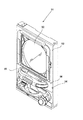
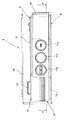
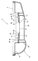
図8、図2〜図4は、それぞれ、中扉5の正面図、前方斜視図、平面図、後方斜視図であり、図5、図6は、中扉5の分解斜視図である(なお、図3、図5、図6においては、一部の部材の記載が省略されている)。中扉5のあて板9は、合成樹脂によって一体的に形成されている。そして、横長な長方形状の平板部12の上端に、折返し部24が、平板部12の裏面から突出するように設けられており、その折返し部24の上面には、3つの係合突起25,25・・が、ほぼ等間隔で設置されている。一方、平板部12の下端に、底板13が、平板部12の前面から突出するように設けられており、その底板13の上面の中央後方には、幅広な直方体状の取付部26が突設されているとともに、取付部26の左右両側には、嵌合凹部27,27が設けられている。各嵌合凹部27,27の内部の内側の壁面には、挿入孔49が穿設されており、各嵌合凹部27,27の奥側には、後方基板48が位置している。また、各嵌合凹部27,27の前方には、それぞれ、ガイド溝57が連設されている。さらに、取付部26の前面板41の裏面であって、左右両端の嵌合凹部27,27と隣接する部位には、それぞれ、断面L字状で幅広な2つのガイド突起45,45が、先端の折れ曲がった部分を互いに内側に向け合った状態で、上下に平行に併設されている。また、取付部26の前面板41の各ガイド突起45,45・・と隣接した内側には、それぞれ、スリット46が穿設されている。さらに、左右2組のガイド突起45,45の間には、それぞれ2個ずつ係着孔47,47が穿設されている。一方、平板部12の左上方には、遊技球払出口14が穿設されており、平板部12の右中央には、正方形状の供給口15が穿設されている。そして、平板部12の裏面の供給口15穿設部位の周囲には、発射装置に遊技球を1個ずつ送り出すための整流機構44が設けられている。
【0011】
また、供給皿16は、合成樹脂によって一体形成された皿本体6、カバー部材10、球貸装置11等によって組み立て形成されている。皿本体6は、水平に設けられた球受け部17の後端縁に、鉛直板18が下向きに突設された形状を有している。そして、球受け部17の左側には、受球凹部19が設けられており、右下がりに傾斜した状態になっている。さらに、受球凹部19の右側には、遊技球約1個分の幅を有する誘導溝20が連設されている。なお、球受け部17の右側には、球抜きレバー21、バネ部材22、可動部材23等からなる球抜き機構43が付設されている。加えて、球受け部17の前側の周囲には、嵌合帯状体28が突設されている。
【0012】
一方、カバー部材10は、下向きにコ字状のフレーム部29の前方に、被覆部30が突設された形状を有している。フレーム部29は、あて板9の平板部12の外周形状とほぼ同様な外周形状を有しており、上端が、後方に折り返されて折返し板31になっている。そして、その折返し板31には、ほぼ等間隔に、係合孔32,32・・が穿設されている。また、被覆部30は、皿本体6の球受け部17の前側の周縁と一致するように、前方に突出しており、ほぼ中央に、球貸装置11に設けられた3つの球貸操作部11a,11b,11cを嵌め込むための嵌合孔50a,50b,50cが設けられている。さらに、被覆部30の裏面の上端際には、嵌合溝33が周設されており、被覆部30の裏側の下端際であって、球貸装置11の設置部位の両サイドには、四角柱状で中空の嵌合突起34,34が突設されている。そして、各嵌合突起34,34の先端際の左右両サイドには、挿通孔35,35が穿設されている。
【0013】
上記した皿本体6、カバー部材10、球貸装置11等からなる供給皿16は、2つのロック部材36,36によって、あて板9に着脱自在に取り付けられている。各ロック部材36,36は、あて板9の裏面に突設された上下一対のガイド突起45,45の間隔とほぼ同一間隔を有する帯状に形成されており、前面の内側の端縁際に、係着ピン38が設けられている。また、裏面の中央に、摘み39が突設されており、裏面の内側の端縁際に、ストッパ40が突設されている。
【0014】
図9〜図11は、中扉5の組み立て構造を、図8のA−A線断面において示したものである。中扉5を組み立てる場合には、まず、皿本体6の嵌合帯状体28をカバー部材10の裏面の嵌合溝33に嵌合させて、皿本体6をカバー部材10に装着する。一方、あて板9の裏面において、左右の一対のガイド突起45,45・・の間に、それぞれ、ロック部材36,36を挿入し、各ロック部材36,36の係着ピン38を、あて板9の前面板41に穿設されている係着孔47,47のうちの内側の係着孔47に嵌入させる。次に、カバー部材10のフレーム部29の折返し板31を、あて板9の折返し部24と重ね合わせ、係合突起25,25・・を係合孔32,32・・に係着させる。また、それと同時に、図9の如く、カバー部材10の裏面に突設された嵌合突起34,34を、あて板9の左右のガイド溝57,57に沿わせて、嵌合凹部27,27に挿入し、図10の如く、各嵌合突起34,34の挿通孔35,35を、ロック部材36,36の先端部分(係着ピン38と反対側の部分)の外側に位置させる。しかる後、図11の如く、各ロック部材36,36を、それぞれ、外側にスライドさせて、各ロック部材36,36の先端部分を、各嵌合突起34,34の挿通孔35,35に挿通させ、各ロック部材36,36の係着ピン38を、外側の係着孔47に嵌入させる(なお、上記手順は、中扉5の組み立て手順の一例であり、中扉5の組み立て手順は、上記手順に何ら限定されない)。
【0015】
上記の如く組み立てられた中扉5においては、皿本体6の左側の受球凹部19が、あて板9に穿設された遊技球払出口14の前方に位置し、誘導溝20の先端が、あて板9に穿設された供給口15と連通した状態になっている。また、平板部12の中央よりやや上方に、皿本体6の球受け部17が配置され、底板13が、その皿本体6と平行に配置された状態になっている。なお、あて板9に取り付けられた皿本体6の受球凹部19の前方には、モール部材42が取り付けられている。
【0016】
かかるパチンコ機1においては、供給皿16の受球凹部19に遊技球が供給されると、それらの遊技球は、誘導溝20、供給口15を介して、あて板6の裏側に付設された整流機構44へと送り出され、1個ずつ発射装置へ送り出される。また、遊技領域に設けられた各種の入賞装置へ遊技球が入賞した場合には、機台の内部に設けられた遊技球払出装置(図示せず)から、賞品球が払い出され、遊技球払出口14を介して、供給皿16へ排出される。
【0017】
パチンコ機1は、上記の如く、供給皿16の裏面(カバー部材10の裏面)に、先端際に挿通孔35,35を設けた嵌合突起34,34が設けられているとともに、あて板9に嵌合凹部27,27が設けられており、あて板9の裏面にロック部材36,36を移動可能に係着し、供給皿16の嵌合突起34,34をあて板9の嵌合凹部27,27に挿入し、嵌合突起34,34の挿通孔35,35にロック部材36,36を挿通させることによって、供給皿16があて板9に着脱自在に取り付けられているため、長時間使用された場合でも、供給皿16のあて板9への取付強度が低下したりしない。また、製造時においては、供給皿16をあて板9にきわめて容易に取り付けることができる。さらに、損傷した供給皿16を修理する場合には、供給皿16をあて板9から容易に取り外すことができる。
【0018】
また、パチンコ機1は、あて板9に水平な折返し部24が形成されているとともに、供給皿16の上端縁(カバー部材10の上端縁)が、あて板9の折返し部24と同方向に折り返し形成されており(折返し板31)、その折返し部分31が、あて板9の折返し部24に、積み重ねられた状態で着脱自在に係着されているため、供給皿16とあて板9との取付強度がきわめて高く、強い衝撃を受けた場合でも、決して供給皿16があて板9から外れたりしない。
【0019】
さらに、パチンコ機1は、あて板9の嵌合凹部27,27の前方に、それぞれ、ガイド溝57が設けられているので、それらのガイド溝57,57に沿わせることによって、供給皿16の嵌合突起34,34を、非常に簡単に、あて板9の嵌合凹部27,27に挿入することができる。したがって、製造時やメンテナンス時における中扉5の組み立てがきわめて容易である。加えて、供給皿16とあて板9との取付強度が一段と高いものとなっている。
【0020】
なお、本発明のパチンコ機の構成は、何ら上記実施形態の態様に限定されるものではなく、外枠、前枠、中扉、(あて板、供給皿(皿本体、カバー部材、球貸装置等)等)、下側機能部、球抜き機構、整流機構、ロック部材、モール部材等の材質・形状・構造等の構成を、必要に応じて適宜変更することができる。
【0021】
たとえば、供給皿は、上記実施形態の如く、皿本体、カバー部材、球貸装置等の複数の部材からなるものに限定されず、一体的に形成したものでも良い。しかしながら、供給皿が、上記実施形態の如く、皿本体、カバー部材、球貸装置等の複数の部材からなるものである場合には、各部材を射出成形等によって容易に安価に形成することができる、というメリットがある。
【0022】
また、供給皿に設ける嵌合突起の個数は、2個に限定されず、1個でも良いし、3個以上でも良い。さらに、嵌合突起の設置位置も、供給皿の裏面の下端際に限定されず、供給皿の裏面の中央等、任意の位置に変更することができる。加えて、嵌合突起は、先端際に挿通孔を設けたものであれば良く、中空状のものに何ら限定されない。また、場合によっては、嵌合突起の先端際に、挿通孔の代わりに窪みを設けることも可能である。
【0023】
一方、パチンコ機は、中扉が前枠とは別個に片開き自在に蝶着されたものに限定されず、中扉が前枠と一体になったものでも良い。
【0024】
また、ロック部材は、突設された係着ピンをあて板の係着孔に嵌入することによってあて板に固定されるものに限定されず、穿設された係着孔にあて板に突設された係着ピンを嵌入させることによってあて板に固定されるものでも良いし、係着機構が設けられていないものでも良い。なお、ロック部材およびあて板に係着機構を設けた場合には、供給皿のあて板への取付強度の保持が、より信頼性の高いものとなる。
【0025】
【発明の効果】
請求項1に記載されたパチンコ機は、あて板の上端縁に沿って、水平な折返し部を後方へ突出するように形成するとともに、あて板の下端縁に沿って、前方へ突出する底板を設ける一方、供給皿の上端縁を、あて板の折返し部と同方向に折り返し形成し、供給皿が、その折返し部分をあて板の折返し部に重合し、且つ、底板上に載置された状態で着脱自在に係着されているため、供給皿とあて板との取付強度がきわめて高く、強い衝撃を受けた場合でも、決して供給皿があて板から外れたりしない。
【0026】
請求項2に記載されたパチンコ機は、供給皿の裏面に嵌合突起を設ける一方、あて板に嵌合部を設け、かつ、底板の該嵌合部の前方となる位置に嵌合突起をガイドするガイド溝を設けたため、供給皿の嵌合突起を、非常に簡単にあて板の嵌合部に挿入することができる。したがって、製造時やメンテナンス時における供給皿とあて板との組み立てがきわめて容易である。また、供給皿とあて板との取付強度が一段と高いものとなっている。
【0027】
請求項3に記載されたパチンコ機は、嵌合突起に挿通孔を設けるとともに、あて板の裏面にロック部材を移動可能に係着し、供給皿の嵌合突起をあて板の嵌合部に挿入した状態で、あて板の裏面において嵌合突起の挿通孔にロック部材を挿通させることによって、供給皿をあて板に取り付けたため、長時間使用された場合でも、供給皿のあて板への取付強度が低下したりしない。また、製造時においては、供給皿をあて板にきわめて容易に取り付けることができる。さらに、損傷した供給皿を修理する場合には、供給皿をあて板から容易に取り外すことができる。
【図面の簡単な説明】
【図1】 パチンコ機を示す説明図である。
【図2】 中扉を示す説明図である。
【図3】 中扉を示す説明図である。
【図4】 中扉を示す説明図である。
【図5】 中扉を示す説明図である。
【図6】 中扉を示す説明図である。
【図7】 従来のパチンコ機を示す説明図である。
【図8】 中扉を示す説明図である。
【図9】 中扉の組み立て構造を示す説明図である。
【図10】 中扉の組み立て構造を示す説明図である。
【図11】 中扉の組み立て構造を示す説明図である。
【符号の説明】
1・・パチンコ機、2・・外枠、3・・前枠、4・・ガラス板、5・・中扉、6・・皿本体、7・・下側機能部、8・・貯留皿、9・・あて板、10・・カバー部材、11・・球貸装置、11a〜11c・・操作部、12・・平板部、13・・底板、14・・遊技球払出口、15・・供給口、16・・供給皿、17・・球受け部、18・・鉛直板、19・・受球凹部、20・・誘導溝、21・・球抜きレバー、22・・バネ部材、23・・可動部材、24・・折返し部、25・・係合突起、26・・取付部、27・・嵌合凹部、28・・嵌合帯状体、29・・フレーム部、30・・被覆部、31・・折返し部、32・・係合孔、33・・嵌合溝、34・・嵌合突起、35・・挿通孔、36・・ロック部材、38・・係着ピン、39・・摘み、40・・ストッパ、41・・前面板、42・・モール部材、43・・球抜き機構、44・・整流機構、45・・ガイド突起、46・・スリット、47・・係着孔、48・・後方基板、49・・挿入孔、50a〜50c・・嵌合孔、51・・パチンコ機、52・・遊技領域、53・・前枠、54・・中扉、55・・供給皿、56・・あて板、57・・ガイド溝。[0001]
BACKGROUND OF THE INVENTION
The present invention relates to a pachinko machine.
[0002]
[Prior art]
A conventional pachinko machine as shown in FIG. 7 is known. The
[0003]
[Problems to be solved by the invention]
However, when the
[0004]
The object of the present invention is to solve the problems of the conventional pachinko machine, and even when used for a long period of time, the mounting strength of the supply tray to the counter plate does not decrease, and the supply tray at the time of manufacture It is an object of the present invention to provide a practical pachinko machine that can be easily attached to the cover plate and can easily be removed from the plate when the damaged supply tray is repaired.
[0005]
[Means for Solving the Problems]
Among the present inventions, the structure of the invention described in claim 1 is that a game area is provided above the center of the front surface, and a supply tray for supplying game balls to the launching device is attached to the hitting plate. A pachinko machine in which the door is installed on the lower side of the game area so as to be freely openable, and is formed so that a horizontal folded portion protrudes rearward along the upper edge of the address plate, and the lower end of the address plate along the edge, while providing a bottom plate which projects forwardly, the upper edge of the feed pan, and folded form the folded portion in the same direction of the wear plate, feed dish, polymerized in the folded portion of the plate against the folded portion In addition, it is detachably attached in a state where it is placed on the bottom plate .
[0006]
According to a second aspect of the present invention, in the first aspect of the present invention, the fitting projection is provided on the back surface of the supply tray, the fitting portion is provided on the cover plate , and the bottom plate is fitted. A guide groove for guiding the fitting protrusion is provided at a position in front of the portion, and the supply tray is attached to the contact plate by inserting the fitting protrusion into the fitting portion along the guide groove. .
[0007]
According to a third aspect of the present invention, in the second aspect of the present invention, the insertion protrusion is provided in the fitting protrusion, and the lock member is movably engaged with the back surface of the cover plate, In a state where the fitting protrusion is inserted into the fitting portion of the contact plate, the supply plate is attached to the contact plate by inserting the lock member into the insertion hole of the fitting protrusion on the back surface of the contact plate.
[0008]
DETAILED DESCRIPTION OF THE INVENTION
Hereinafter, an embodiment of a pachinko machine according to the present invention will be described in detail with reference to the drawings.
[0009]
FIG. 1 shows a pachinko machine according to the present invention. The pachinko machine 1 is provided with a game area (not shown) in the upper center of the front surface. In the game area, various winning devices (not shown) are installed, and many obstacle nails ( (Not shown) is planted. Further, a middle frame (not shown) is installed inside the
[0010]
8 and 2 to 4 are a front view, a front perspective view, a plan view, and a rear perspective view, respectively, of the
[0011]
Further, the
[0012]
On the other hand, the
[0013]
The
[0014]
9 to 11 show the assembled structure of the
[0015]
In the
[0016]
In the pachinko machine 1, when game balls are supplied to the
[0017]
As described above, the pachinko machine 1 is provided with the
[0018]
In the pachinko machine 1, a
[0019]
Further, the pachinko machine 1 is provided with
[0020]
In addition, the structure of the pachinko machine of the present invention is not limited to the aspect of the above-described embodiment, but includes an outer frame, a front frame, an inner door, (a plate, a supply plate (a plate body, a cover member, a ball lending device). Etc.), etc.), the structure of the material, shape, structure, etc. of the lower functional part, the ball removing mechanism, the rectifying mechanism, the lock member, the molding member, etc. can be changed as necessary.
[0021]
For example, the supply tray is not limited to a plurality of members such as a plate body, a cover member, and a ball lending device as in the above embodiment, and may be integrally formed. However, when the supply tray is composed of a plurality of members such as a tray body, a cover member, and a ball lending device as in the above embodiment, each member can be easily formed at low cost by injection molding or the like. There is a merit that it is possible.
[0022]
Further, the number of fitting protrusions provided on the supply tray is not limited to two, and may be one or three or more. Furthermore, the installation position of the fitting protrusion is not limited to the lower end of the back surface of the supply tray, and can be changed to any position such as the center of the back surface of the supply tray. In addition, the fitting protrusion is not limited to a hollow shape as long as an insertion hole is provided at the tip. In some cases, a recess may be provided instead of the insertion hole at the tip of the fitting protrusion.
[0023]
On the other hand, the pachinko machine is not limited to the one in which the middle door is hinged so as to be freely opened separately from the front frame, and the middle door may be integrated with the front frame.
[0024]
Further, the lock member is not limited to the one fixed to the contact plate by fitting the protruded engagement pin into the engagement hole of the contact plate, and protrudes from the contact plate to the formed engagement hole. The engagement pin may be fixed to the target plate by fitting, or the engagement mechanism may not be provided. In addition, when the engaging mechanism is provided in the lock member and the address plate, the attachment strength of the supply tray to the address plate is more reliable.
[0025]
【The invention's effect】
In the pachinko machine according to claim 1 , a horizontal folded portion is formed so as to protrude rearward along the upper edge of the cover plate, and a bottom plate protruding forward is formed along the lower edge of the cover plate. On the other hand, the upper edge of the supply tray is folded back in the same direction as the folded portion of the address plate , and the supply tray is superposed on the folded portion of the address plate and placed on the bottom plate Since the attachment plate and the contact plate are attached to each other in a detachable manner, the supply plate is never detached from the contact plate even when subjected to a strong impact.
[0026]
The pachinko machine according to
[0027]
The pachinko machine according to claim 3 is provided with an insertion hole in the fitting projection, and a lock member is movably engaged with the back surface of the contact plate, and the fitting projection of the supply tray is attached to the fitting portion of the contact plate. In the inserted state, the supply plate is attached to the contact plate by inserting the lock member into the insertion hole of the fitting protrusion on the back surface of the contact plate, so even if it is used for a long time, the supply plate is attached to the contact plate The strength does not decrease. Further, at the time of manufacture, the supply tray can be attached to the contact plate very easily. Furthermore, when repairing a damaged supply tray, the supply tray can be easily removed from the application plate.
[Brief description of the drawings]
FIG. 1 is an explanatory view showing a pachinko machine.
FIG. 2 is an explanatory view showing an inner door.
FIG. 3 is an explanatory view showing an inner door.
FIG. 4 is an explanatory view showing an inner door.
FIG. 5 is an explanatory view showing an inner door.
FIG. 6 is an explanatory view showing an inner door.
FIG. 7 is an explanatory view showing a conventional pachinko machine.
FIG. 8 is an explanatory view showing an inner door.
FIG. 9 is an explanatory view showing an assembly structure of the inner door.
FIG. 10 is an explanatory view showing an assembly structure of the inner door.
FIG. 11 is an explanatory view showing an assembly structure of the inner door.
[Explanation of symbols]
1 ....
Claims (3)
あて板の上端縁に沿って、水平な折返し部を後方へ突出するように形成するとともに、あて板の下端縁に沿って、前方へ突出する底板を設ける一方、供給皿の上端縁を、あて板の折返し部と同方向に折り返し形成し、
供給皿が、その折返し部分をあて板の折返し部に重合し、且つ、底板上に載置された状態で着脱自在に係着されていることを特徴とするパチンコ機。A pachinko is provided with a game area in the upper center of the front, and a middle door attached to a plate to which a supply tray for supplying game balls to the launcher is attached to the lower side of the game area. Machine,
Along the upper edge of the wear plate, as well as formed to project the horizontal folded portion rearwardly along the lower edge of the wear plate, while providing a bottom plate which projects forwardly, the upper edge of the feed pan, addressed folded to form the folded portion in the same direction of the plate,
Feed dish, then polymerized to the folded portion of the wear plate that the folded portion, and, pachinko machines, characterized in that it is engaged detachably in a state of being placed on the bottom plate.
ガイド溝に沿わせながら嵌合突起を嵌合部に挿入することによって、供給皿をあて板に取り付けたことを特徴とする請求項1に記載のパチンコ機。While providing a fitting projection on the back surface of the supply tray, the fitting plate is provided with a fitting portion, and a guide groove for guiding the fitting projection is provided at a position in front of the fitting portion of the bottom plate ,
The pachinko machine according to claim 1, wherein the supply tray is attached to the contact plate by inserting the fitting protrusion into the fitting portion along the guide groove.
供給皿の嵌合突起をあて板の嵌合部に挿入した状態で、あて板の裏面において嵌合突起の挿通孔にロック部材を挿通させることによって、供給皿をあて板に取り付けたことを特徴とする請求項2に記載のパチンコ機。An insertion hole is provided in the fitting protrusion, and a lock member is movably attached to the back surface of the address plate,
With the fitting projection of the supply tray inserted into the fitting portion of the contact plate, the supply plate is attached to the contact plate by inserting the lock member through the insertion hole of the fitting projection on the back surface of the contact plate. The pachinko machine according to claim 2.
Priority Applications (1)
| Application Number | Priority Date | Filing Date | Title |
|---|---|---|---|
| JP23736798A JP4345112B2 (en) | 1998-08-24 | 1998-08-24 | Pachinko machine |
Applications Claiming Priority (1)
| Application Number | Priority Date | Filing Date | Title |
|---|---|---|---|
| JP23736798A JP4345112B2 (en) | 1998-08-24 | 1998-08-24 | Pachinko machine |
Related Child Applications (1)
| Application Number | Title | Priority Date | Filing Date |
|---|---|---|---|
| JP17132099A Division JP3485030B2 (en) | 1999-06-17 | 1999-06-17 | Pachinko machine |
Publications (3)
| Publication Number | Publication Date |
|---|---|
| JP2000061108A JP2000061108A (en) | 2000-02-29 |
| JP2000061108A5 JP2000061108A5 (en) | 2005-10-27 |
| JP4345112B2 true JP4345112B2 (en) | 2009-10-14 |
Family
ID=17014348
Family Applications (1)
| Application Number | Title | Priority Date | Filing Date |
|---|---|---|---|
| JP23736798A Expired - Fee Related JP4345112B2 (en) | 1998-08-24 | 1998-08-24 | Pachinko machine |
Country Status (1)
| Country | Link |
|---|---|
| JP (1) | JP4345112B2 (en) |
Families Citing this family (1)
| Publication number | Priority date | Publication date | Assignee | Title |
|---|---|---|---|---|
| JP4598185B2 (en) * | 2005-02-14 | 2010-12-15 | 株式会社Mrd | Game machine |
-
1998
- 1998-08-24 JP JP23736798A patent/JP4345112B2/en not_active Expired - Fee Related
Also Published As
| Publication number | Publication date |
|---|---|
| JP2000061108A (en) | 2000-02-29 |
Similar Documents
| Publication | Publication Date | Title |
|---|---|---|
| JP4139460B2 (en) | Pachinko machine | |
| JP4345112B2 (en) | Pachinko machine | |
| JP3485030B2 (en) | Pachinko machine | |
| JP2000061108A5 (en) | ||
| JP3161446B2 (en) | Pachinko machine | |
| JP2008023182A (en) | Pachinko machine | |
| JP4269234B2 (en) | Game machine | |
| JPH0632144Y2 (en) | Deflection-preventing structure of a guide gutter in a pachinko machine | |
| JP2008023184A (en) | Pachinko machine | |
| JP4928163B2 (en) | Pachinko machine | |
| JP5070538B2 (en) | Pachinko machine | |
| JP2000140342A (en) | Ball receiving tray assembling structure for pachinko machine | |
| JP5433841B2 (en) | Pachinko machine | |
| JP2006020809A (en) | Game machine | |
| JPH0749982Y2 (en) | Pachinko machine | |
| JP4370014B2 (en) | Pachinko machine hitting tray | |
| JP3161445B2 (en) | Pachinko machine | |
| JP2532928Y2 (en) | Main mechanism cover body for mechanism plate | |
| JP3164102B2 (en) | Pachinko machine | |
| JP3998537B2 (en) | Ball delivery device mounting structure and game machine | |
| JPH0354766Y2 (en) | ||
| JP2000116899A (en) | Pachinko machine | |
| JP4928162B2 (en) | Pachinko machine | |
| JPH10179880A (en) | Pachinko machine | |
| JP3116945B2 (en) | Pachinko machine |
Legal Events
| Date | Code | Title | Description |
|---|---|---|---|
| A521 | Written amendment |
Free format text: JAPANESE INTERMEDIATE CODE: A523 Effective date: 20050822 |
|
| A621 | Written request for application examination |
Free format text: JAPANESE INTERMEDIATE CODE: A621 Effective date: 20050823 |
|
| A977 | Report on retrieval |
Free format text: JAPANESE INTERMEDIATE CODE: A971007 Effective date: 20081119 |
|
| A131 | Notification of reasons for refusal |
Free format text: JAPANESE INTERMEDIATE CODE: A131 Effective date: 20081209 |
|
| A521 | Written amendment |
Free format text: JAPANESE INTERMEDIATE CODE: A523 Effective date: 20090202 |
|
| TRDD | Decision of grant or rejection written | ||
| A01 | Written decision to grant a patent or to grant a registration (utility model) |
Free format text: JAPANESE INTERMEDIATE CODE: A01 Effective date: 20090623 |
|
| A01 | Written decision to grant a patent or to grant a registration (utility model) |
Free format text: JAPANESE INTERMEDIATE CODE: A01 |
|
| A61 | First payment of annual fees (during grant procedure) |
Free format text: JAPANESE INTERMEDIATE CODE: A61 Effective date: 20090706 |
|
| R150 | Certificate of patent or registration of utility model |
Free format text: JAPANESE INTERMEDIATE CODE: R150 |
|
| FPAY | Renewal fee payment (event date is renewal date of database) |
Free format text: PAYMENT UNTIL: 20120724 Year of fee payment: 3 |
|
| FPAY | Renewal fee payment (event date is renewal date of database) |
Free format text: PAYMENT UNTIL: 20120724 Year of fee payment: 3 |
|
| FPAY | Renewal fee payment (event date is renewal date of database) |
Free format text: PAYMENT UNTIL: 20150724 Year of fee payment: 6 |
|
| R250 | Receipt of annual fees |
Free format text: JAPANESE INTERMEDIATE CODE: R250 |
|
| LAPS | Cancellation because of no payment of annual fees |