JP4354363B2 - Futon Pass - Google Patents
Futon Pass Download PDFInfo
- Publication number
- JP4354363B2 JP4354363B2 JP2004221383A JP2004221383A JP4354363B2 JP 4354363 B2 JP4354363 B2 JP 4354363B2 JP 2004221383 A JP2004221383 A JP 2004221383A JP 2004221383 A JP2004221383 A JP 2004221383A JP 4354363 B2 JP4354363 B2 JP 4354363B2
- Authority
- JP
- Japan
- Prior art keywords
- net
- partial
- partition
- unit
- futon
- Prior art date
- Legal status (The legal status is an assumption and is not a legal conclusion. Google has not performed a legal analysis and makes no representation as to the accuracy of the status listed.)
- Expired - Fee Related
Links
- 238000005192 partition Methods 0.000 claims description 27
- 238000010276 construction Methods 0.000 description 4
- 238000000638 solvent extraction Methods 0.000 description 2
- 230000003247 decreasing effect Effects 0.000 description 1
- 238000004519 manufacturing process Methods 0.000 description 1
Images


Landscapes
- Pit Excavations, Shoring, Fill Or Stabilisation Of Slopes (AREA)
- Revetment (AREA)
Description
本発明は、法面保護工、護岸工などに使用されるフトン篭で、特に長さ調整可能なフトン篭に関する。 TECHNICAL FIELD The present invention relates to a futon scissor used for slope protection work, revetment work, etc., and particularly to a futon scissor whose length is adjustable.
法面保護工、護岸工などに使用されるフトン篭は、例えば下記特許文献1〜5等に開示されている。このようなフトン篭は、法面などに付設し内部に割石を詰め、付設面の安定を図るものである。このうち、特許文献1では幅調整可能なフトン篭が、特許文献5には長さ調整可能なフトン篭が提案されている。
前記特許文献5の長さ調整可能なフトン篭は、底網を複数の部分底網から形成して長さ調節可能とし、ジョイントする2つの部分底網の一方の端部に仕切網を設けている。ジョイント部は、コイル線で連結するのであるが、このジョイント部では底網に対して直角に仕切網が交わり、側網に対しても仕切網が直角に交わっているので、これらのT字状に交わった網の交点にコイル線を施工しなければならず、ジョイント作業が煩雑で能率が悪かった。本発明は、ジョイント部におけるコイル線の施工を容易にし、ジョイント作業能率を向上させることを課題としている。
The length-adjustable Futon jar of
本発明は、底網と、該底網の両端に幅方向に設けた幅網と、該底網に長さ方向に設けた側網で箱状に形成され、内部を仕切るために幅方向に設けられた仕切網を有するフトン篭であって、少なくとも、前記底網の一部を構成する四辺形状の部分底網と、該部分底網の1辺又は対向する2辺に設けられた前記側網の一部を構成する部分側網と、前記部分底網のジョイント端部以外の中間部に前記部分側網と直角方向に設けられた前記仕切網を有する複数のユニットで組み立てられ、該ユニットを長さ方向にジョイントする際に、前記仕切網が形成されていないジョイント端部どうしを重ね合わせることでフトン篭の長さ調節が可能であり、ジョイント部において、各ユニットの部分底網どうし、及び部分側網どうしのみをコイル線で連結したことを特徴とするフトン篭である。 The present invention is formed in a box shape by a bottom mesh, a width mesh provided in the width direction at both ends of the bottom mesh, and a side mesh provided in the length direction on the bottom mesh, and in the width direction to partition the inside. A futon wall having a partition net provided, at least, a quadrilateral partial bottom net constituting a part of the bottom net, and the side provided on one side or two opposite sides of the partial bottom net Assembled by a plurality of units having a part side net constituting a part of the net and the partition net provided in a direction perpendicular to the part side net at an intermediate portion other than the joint end of the partial bottom net, the when the joint in the longitudinal direction, the partition net is adjustable length of futon basket by superimposing the joint ends to each other which is not formed in the joint portion, portions bottom networks to each other of each unit, and this for only part side network each other and connected by coil wire A futon basket characterized by.
本発明において、側網は底網の両端部のみならず中間に設けることもできる。中間に設けた側網によって、フトン篭内部が縦に仕切られる。 In the present invention , the side net can be provided not only at both ends of the bottom net but in the middle. The inner side of the futon bowl is vertically partitioned by a side net provided in the middle.
本発明は、フトン篭をユニット化したので、ユニットを工場生産し、現場においてはユニットを組み立てることで容易にフトン篭を施工することができる。 The present invention, since the unit of the full tons basket, the unit is factory production, in the field may be applied easily futon basket by assembling the unit.
本発明のフトン篭は、ジョイント端部に仕切網がないので、コイル線で連結する際に、単に部分底網どうし又は部分側網どうしを連結すれば良く、ジョイント部におけるコイル線の施工が容易で、ジョイント作業能率が向上する。 Since the futon cage of the present invention has no partition net at the joint end, when connecting with the coil wire, it is only necessary to connect the partial bottom nets or the partial side nets, and the coil wire can be easily constructed at the joint part. As a result, joint work efficiency is improved.
以下、実施例を表した図面に基づいて本発明を詳細に説明する。図1はフトン篭の施工状態の一例の斜視図、図2は法面部のユニット分解図、図3は垂面部のユニット分解図、図4は天面部のユニット分解図、図5はジョイント部の説明図である。 Hereinafter, the present invention will be described in detail with reference to the drawings showing examples. FIG. 1 is a perspective view of an example of the construction state of the Futon ridge, FIG. 2 is a unit exploded view of the slope part, FIG. 3 is a unit exploded view of the vertical part, FIG. 4 is a unit exploded view of the top part, and FIG. It is explanatory drawing.
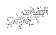
図1のフトン篭は、法面部1、垂面部2及び天面部3からなる。これら各部は、底網5、幅網6及び側網7で箱状に形成され、しかも中間に2列の側網7と多数の仕切網8を有し、これらによって多数の領域に仕切られている。
1 includes a slope portion 1, a vertical surface portion 2, and a top surface portion 3. Each of these parts is formed in a box shape with a
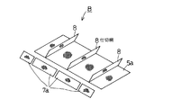
法面部1は本発明の実施例で、図2に示すように、ユニットA〜Fを組み立てたものである。ユニットA及びユニットCは部分底網5a、幅網6、部分側網7a及び2枚の仕切網8を一体に組み立てたもので、仕切網8はジョイント端部4以外の中間部に設けられている。ユニットBは部分底網5a、部分側網7a及び3枚の仕切網8を一体に組み立てたもので、仕切網8はジョイント端部4以外の中間部に設けられている。ユニットD、E、FはユニットA、B、Cに更に部分側網7aを設け、両側に部分側網7aを配置したものである。いずれのユニットも部分側網7aの長さは部分底網5aの長さと等しく、幅網6及び仕切網8の長さは部分底網5aの幅と等しくなっている。
The slope portion 1 is an embodiment of the present invention and is constructed by assembling units A to F as shown in FIG. Unit A and unit C are an assembly of a
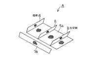
ユニットAとBをジョイントする場合、図5に示すように、任意の長さだけ重ね合わせることができる。この場合、ジョイント部のコイル線による連結は、両ユニットの部分底網どうし、及び部分側網どうしを連結すればよいので、コイル線の施工がきわめて簡単である。ユニットB、Cをジョイントする場合も、これと同様に任意の長さだけ重ね合わせることができる。ユニットD、E、Fについても同様である。ユニットA、B、C及びユニットD、E、Fの重ね合わせる長さを調整することで、フトン篭(法面部)の長さを調整することができる。 When units A and B are joined, as shown in FIG. 5, they can be overlapped by an arbitrary length. In this case, the connection of the joint portion by the coil wire may be achieved by connecting the partial bottom nets and the partial side nets of both units, so that the construction of the coil wire is very simple. In the case where the units B and C are jointed, they can be overlapped by an arbitrary length similarly to this. The same applies to the units D, E, and F. By adjusting the overlapping length of the units A, B, and C and the units D, E, and F, the length of the futon ridge (slope portion) can be adjusted.
法面部1は3列で構成されているが、ユニットA、B、Cを任意の組数設けることで、任意の列数にすることができる。また、各列において、中間のユニットB(最終端においてはユニットE)の数を増やすことで、又は無くすことで任意の長さのフトン篭(法面部)とすることができる。 The slope portion 1 is composed of three rows, but by providing an arbitrary number of units A, B, and C, the number of rows can be increased. Further, in each row, the number of intermediate units B (unit E at the final end) can be increased or eliminated so that a futon ridge (slope portion) having an arbitrary length can be obtained.
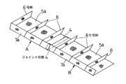
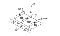
垂面部2も本発明の実施例で、図3に示すように、ユニットG〜Jを組み立てたものである。ユニットGは部分底網5a、部分側網7a及び1枚の仕切網8を一体に組み立てたもので、仕切網8はジョイント端部4以外の中間部に設けられている。ユニットHは部分底網5a、幅網6、部分側網7a及び2枚の仕切網8を一体に組み立てたもので、仕切網8はジョイント端部4以外の中間部に設けられている。ユニットI、JはユニットG、Hに更に部分側網7aを設け、両側に部分側網7aを配置したものである。いずれのユニットも部分側網7aの長さは部分底網5aの長さと等しく、幅網6及び仕切網8の長さは部分底網5aの幅と等しくなっている。なお、法面部1の下端の幅網6は垂面部2の幅網も兼ねている。
The vertical surface portion 2 is also an embodiment of the present invention, and is constructed by assembling units G to J as shown in FIG. The unit G is an assembly of a
垂面部2においても、法面部の場合と同様に、ユニットGとH、ユニットIとJの重ね合わせる長さを調整することで、フトン篭の長さを調整することができる。ユニットの数を増減して列の数及び長さを任意にできることも同様である。 In the vertical surface portion 2 as well, the length of the futon ridges can be adjusted by adjusting the overlapping lengths of the units G and H and the units I and J as in the case of the slope portion. Similarly, the number and length of the columns can be arbitrarily set by increasing or decreasing the number of units.
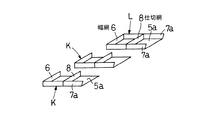
天面部3は、図4に示すように、ユニットK、Lを組み立てたものである。ユニットKは部分底網5a、幅網6、部分側網7a及び1枚の仕切網8を一体に組み立てたもので、ユニットLはユニットKに更に部分側網7aを設け、両側に部分側網7aを配置したものである。天面部3は長さ調整できないものであるが、前記の垂面部2と同様の構成にすることで長さ調整可能にすることもできる。
As shown in FIG. 4, the top surface portion 3 is an assembly of the units K and L. The unit K is an assembly of a
各ユニットA〜Lにおいて、部分側網を別体とすることもできる。更に、部分側網は仕切網と交わる部分で切断して細分化することができる。図6はユニットAにおいて部分側網7aを別体とした例である。図7はユニットAにおいて部分側網7aを別体とすると共に部分側網7aを仕切網と交わる部分で細分化した例である。図8はユニットBにおいて部分側網7aを別体とした例である。図9はユニットBにおいて部分側網7aを別体とすると共に部分側網7aを仕切網と交わる部分で細分化した例である。このように、部分側網を仕切網と交わる部分で細分化すると、各ユニットを幅方向に重ね、幅調整したりカーブ施工することが可能となる。
In each of the units A to L, the partial network can be separated. Furthermore, the partial side net | network can be cut | disconnected and subdivided in the part which crosses a partition net | network. FIG. 6 is an example in which the
1 法面部
2 垂面部
3 天面部
4 ジョイント端部
5 底網
6 幅網
7 側網
8 仕切網
DESCRIPTION OF SYMBOLS 1 Slope part 2 Vertical surface part 3 Top surface part 4
Claims (1)
少なくとも、前記底網の一部を構成する四辺形状の部分底網と、該部分底網の1辺又は対向する2辺に設けられた前記側網の一部を構成する部分側網と、前記部分底網のジョイント端部以外の中間部に前記部分側網と直角方向に設けられた前記仕切網を有する複数のユニットで組み立てられ、
該ユニットを長さ方向にジョイントする際に、前記仕切網が形成されていないジョイント端部どうしを重ね合わせることでフトン篭の長さ調節が可能であり、
ジョイント部において、各ユニットの部分底網どうし、及び部分側網どうしのみをコイル線で連結したことを特徴とするフトン篭。 A partition formed in a box shape by a bottom mesh, a width mesh provided in the width direction at both ends of the bottom mesh, and a side mesh provided in the length direction in the bottom mesh, and provided in the width direction to partition the inside Futon pass with a net,
At least a quadrilateral partial bottom net constituting a part of the bottom net, a partial side net constituting a part of the side net provided on one side or two opposite sides of the partial bottom net, and Assembled with a plurality of units having the partition net provided in a direction perpendicular to the partial side net in an intermediate portion other than the joint end of the partial bottom net,
When the joint of the unit in the longitudinal direction, are possible length adjustment of the futon basket by superimposing the joint end portion with each other for the no partition network is formed,
In the joint part, the Futon ridge , wherein the partial bottom nets and only the partial side nets of each unit are connected by a coil wire .
Priority Applications (1)
| Application Number | Priority Date | Filing Date | Title |
|---|---|---|---|
| JP2004221383A JP4354363B2 (en) | 2004-07-29 | 2004-07-29 | Futon Pass |
Applications Claiming Priority (1)
| Application Number | Priority Date | Filing Date | Title |
|---|---|---|---|
| JP2004221383A JP4354363B2 (en) | 2004-07-29 | 2004-07-29 | Futon Pass |
Publications (2)
| Publication Number | Publication Date |
|---|---|
| JP2006037587A JP2006037587A (en) | 2006-02-09 |
| JP4354363B2 true JP4354363B2 (en) | 2009-10-28 |
Family
ID=35902859
Family Applications (1)
| Application Number | Title | Priority Date | Filing Date |
|---|---|---|---|
| JP2004221383A Expired - Fee Related JP4354363B2 (en) | 2004-07-29 | 2004-07-29 | Futon Pass |
Country Status (1)
| Country | Link |
|---|---|
| JP (1) | JP4354363B2 (en) |
Families Citing this family (1)
| Publication number | Priority date | Publication date | Assignee | Title |
|---|---|---|---|---|
| JP7445803B1 (en) | 2023-04-03 | 2024-03-07 | 前田工繊株式会社 | Net material for multiple futon baskets, multiple futon baskets and their construction method |
-
2004
- 2004-07-29 JP JP2004221383A patent/JP4354363B2/en not_active Expired - Fee Related
Also Published As
| Publication number | Publication date |
|---|---|
| JP2006037587A (en) | 2006-02-09 |
Similar Documents
| Publication | Publication Date | Title |
|---|---|---|
| KR101246268B1 (en) | Structure of gabion wall with vegetation steel frame and constructing method thereof | |
| EP1496166A1 (en) | Space truss | |
| JP4354363B2 (en) | Futon Pass | |
| JP5496121B2 (en) | Water storage space forming block | |
| US11542133B2 (en) | Extendable arm | |
| JP2001107366A (en) | Assembling square stone gabion and its construction method | |
| JP3789224B2 (en) | Ring for hillside sabo net and method for hillside sabo net using the ring | |
| JP4027882B2 (en) | Square shaped stone bowl | |
| JPH052669Y2 (en) | ||
| KR102191982B1 (en) | Assemble type sidewalk block | |
| KR101396531B1 (en) | Triangle multi-insulating vinyl house | |
| JP3450809B2 (en) | Square gabion | |
| JP6796409B2 (en) | Foundation packing | |
| JP3060046B2 (en) | Basket unit | |
| JP3163493B2 (en) | Futon basket for slope | |
| JP6485841B2 (en) | Embankment structure and construction method | |
| JP3091410B2 (en) | Linked stone basket and its construction method | |
| JP3215026U (en) | Composite rhombus wire mesh | |
| JP3038582B1 (en) | Futon basket construction method | |
| JPH069068Y2 (en) | Assembled welding net basket for soil retaining | |
| JP4302283B2 (en) | Aperture reinforcement and method for reinforcing aperture | |
| JPH0348268Y2 (en) | ||
| JP2003096744A (en) | Foldable square gabion, gabion package, and handling method for gabion | |
| JP3981960B2 (en) | Revetment block and its laying method | |
| JP2012127129A (en) | Gabion |
Legal Events
| Date | Code | Title | Description |
|---|---|---|---|
| A621 | Written request for application examination |
Free format text: JAPANESE INTERMEDIATE CODE: A621 Effective date: 20070608 |
|
| A977 | Report on retrieval |
Free format text: JAPANESE INTERMEDIATE CODE: A971007 Effective date: 20090220 |
|
| A131 | Notification of reasons for refusal |
Free format text: JAPANESE INTERMEDIATE CODE: A131 Effective date: 20090317 |
|
| A521 | Written amendment |
Free format text: JAPANESE INTERMEDIATE CODE: A523 Effective date: 20090515 |
|
| TRDD | Decision of grant or rejection written | ||
| A01 | Written decision to grant a patent or to grant a registration (utility model) |
Free format text: JAPANESE INTERMEDIATE CODE: A01 Effective date: 20090728 |
|
| A01 | Written decision to grant a patent or to grant a registration (utility model) |
Free format text: JAPANESE INTERMEDIATE CODE: A01 |
|
| A61 | First payment of annual fees (during grant procedure) |
Free format text: JAPANESE INTERMEDIATE CODE: A61 Effective date: 20090729 |
|
| R150 | Certificate of patent or registration of utility model |
Ref document number: 4354363 Country of ref document: JP Free format text: JAPANESE INTERMEDIATE CODE: R150 Free format text: JAPANESE INTERMEDIATE CODE: R150 |
|
| FPAY | Renewal fee payment (event date is renewal date of database) |
Free format text: PAYMENT UNTIL: 20120807 Year of fee payment: 3 |
|
| FPAY | Renewal fee payment (event date is renewal date of database) |
Free format text: PAYMENT UNTIL: 20120807 Year of fee payment: 3 |
|
| FPAY | Renewal fee payment (event date is renewal date of database) |
Free format text: PAYMENT UNTIL: 20170807 Year of fee payment: 8 |
|
| R250 | Receipt of annual fees |
Free format text: JAPANESE INTERMEDIATE CODE: R250 |
|
| S111 | Request for change of ownership or part of ownership |
Free format text: JAPANESE INTERMEDIATE CODE: R313117 |
|
| FPAY | Renewal fee payment (event date is renewal date of database) |
Free format text: PAYMENT UNTIL: 20170807 Year of fee payment: 8 |
|
| R350 | Written notification of registration of transfer |
Free format text: JAPANESE INTERMEDIATE CODE: R350 |
|
| R250 | Receipt of annual fees |
Free format text: JAPANESE INTERMEDIATE CODE: R250 |
|
| R250 | Receipt of annual fees |
Free format text: JAPANESE INTERMEDIATE CODE: R250 |
|
| LAPS | Cancellation because of no payment of annual fees |