JP4354603B2 - Door lock device - Google Patents

Door lock device Download PDF

Info

Publication number
JP4354603B2
JP4354603B2 JP2000005788A JP2000005788A JP4354603B2 JP 4354603 B2 JP4354603 B2 JP 4354603B2 JP 2000005788 A JP2000005788 A JP 2000005788A JP 2000005788 A JP2000005788 A JP 2000005788A JP 4354603 B2 JP4354603 B2 JP 4354603B2
Authority
JP
Japan
Prior art keywords
lever
latch
hook
base plate
door
Prior art date
Legal status (The legal status is an assumption and is not a legal conclusion. Google has not performed a legal analysis and makes no representation as to the accuracy of the status listed.)
Expired - Fee Related
Application number
JP2000005788A
Other languages
Japanese (ja)
Other versions
JP2001193328A (en
Inventor
明弘 斉藤
美由紀 芦田
Current Assignee (The listed assignees may be inaccurate. Google has not performed a legal analysis and makes no representation or warranty as to the accuracy of the list.)
Johnan Manufacturing Co Ltd
Original Assignee
Johnan Manufacturing Co Ltd
Priority date (The priority date is an assumption and is not a legal conclusion. Google has not performed a legal analysis and makes no representation as to the accuracy of the date listed.)
Filing date
Publication date
Application filed by Johnan Manufacturing Co Ltd filed Critical Johnan Manufacturing Co Ltd
Priority to JP2000005788A priority Critical patent/JP4354603B2/en
Publication of JP2001193328A publication Critical patent/JP2001193328A/en
Application granted granted Critical
Publication of JP4354603B2 publication Critical patent/JP4354603B2/en
Anticipated expiration legal-status Critical
Expired - Fee Related legal-status Critical Current

Links

Images

Landscapes

  • Lock And Its Accessories (AREA)

Description

【0001】
【発明の属する技術分野】
本発明は、ドアロック装置に関し、特に自動車のバックドア等をロックするのに好適なものに関する。
【0002】
【従来の技術】
従来、自動車がバックドアを半ドア状態で走行しても安全なように、あるいは乱暴にバックドアを車体側に衝突させて本閉じ状態としなくても済むように、半ドア状態から自動的に本閉じ状態に移行するドアロック装置が知られている。
上記従来のドアロック装置について図8〜図13を用いて説明するが、本件発明と多くの点で同じ機構を備えているので、本件発明の前提として詳しく説明する。
【0003】
図8に示すように、自動車の後部開口の下縁には、門形に屈曲したストライカ1が固定してある。
自動車のバックドアBDにはドアロック装置の本体機構2が装着される。本体機構2は、バックドアBDの下面において外部に露出する筺体2aと、この筺体2aの上面(取り付けた状態において)を覆うカバープレート2b及びカバープレート2bから上方に直角に張り出し、バックドア構造の内部に突出して配置される基体となるベースプレート6を備える。これらは厚板で頑丈に構成され、後述の各部材を取り付けた後溶接することにより確実に一体化される。なお、筺体2a及びカバープレート2bの両側には、本体機構2をバックドアBDの下面にボルト止めするためのフランジ14が設けられる。
【0004】
筺体2aとカバープレート2bが構成する収納部には、ラッチ3とディテントレバー11がほぼ上下方向のシャフト4及びシャフト11aによって回動可能に軸支されており、ラッチ3は第1のコイルバネ17によって図11において右回転方向(フルオープン方向)に常時付勢され、また、ディテントレバー11は第2のコイルバネ21によって左回転方向に常時付勢されている。
ラッチ3は、第1の段部18と第2の段部19を有すると共に大きくえぐれた切欠13を備える。切欠13はストライカ1を受け入れる幅と深さを持つ。また、切欠13の前記第2の段部19側は当り面15aとなっていて、ラッチ3のフルオープン位置(図11の状態)では筺体2aの正面に向け、ストライカ進入口15を横断して位置している。
【0005】
ディテントレバー11は、ストライカ進入口15の開口側と逆側に二股に分かれた部分を有し、ラッチ3側の一方が係止突起20とされ、第2のコイルバネ21の付勢で常時ラッチ3の周縁に接しており、他方は当接片22となっている。なお、係止突起20はラッチ3の左回転を許容するが、第1の段部18及び第2の段部19に落ち込むと第1のコイルバネ17の付勢に対抗し、ラッチ3が右回転するのを阻止する。ただし、当接片22に力を加えて右に回動させると、係止突起20と第1及び第2の段部18,19との係合を解くことができる。
【0006】
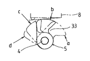
ラッチ3のシャフト4はカバープレート2bを越えてバックドアBDの内部に延び、その先端部にラッチレバー5を固定してある。従って、ラッチレバー5はラッチ3と一体となって、図10に示すように、フルオープン位置aからハーフラッチ位置b及びフルラッチ位置cを経由して、オーバーラン位置dまで可逆的に回動する。
また、ベースプレート6に形成された開口部16を挟んでリミットスイッチ8がカバープレート2bに取付けられている。このスイッチ8はハーフラッチ位置(半ドア状態)を検出するためのものである。
【0007】
図8及び図9に示すように、ベースプレート6の前面には、クローズレバー7が軸7aによって軸着され、ベースプレート6に設けたストッパー6a,6b間を回動するようになっている。
クローズレバー7は細長い桿状に形成され、その下端にラッチレバー5側へ湾曲するフック部32が形成され、クローズレバー7の上端は、クロージャーモータ7cで押し引きされるギヤドワイヤ7bの取り付け部となっている。
クローズレバー7の下端部に形成したフック部32は、ラッチレバー5の側面に形成された係合凹部33と対向し、クローズレバー7が右方向に回動すると、ラッチレバー5を左回転させる。
【0008】
ベースプレート6の前面には、リミットスイッチ9,10が取り付けられる。リミットスイッチ9は、クローズレバー7が図8において右回転してストッパー6bに当接するときにONとなるラッチ位置検出用であり、リミットスイッチ10は、クローズレバー7が左回転してストッパー6aに当接するときにONとなるラッチ位置検出用である。これらのリミットスイッチ8,9,10は図外のコントローラーに接続され、クロージャーモータの駆動を制御する。
【0009】
ベースプレート6の後方にはオープンレバー12が回動可能に軸着されているオープンレバー12は、バックドアBDを構成する構造の内部に位置する操作部12aと、軸25から下方へ延出した作用部12bとが形成されている。作用部12bは前記の筺体2aの内部に入り、ディテントレバー11の当接片22と係合している。
そして、図9に示すように、操作部12aを押してオープンレバー12を左方向に回動させると、作用部は右方向に移動してディテントレバー11の当接片22を回動させ、ラッチ3とディテントレバー11との係合を解除することができる。
【0010】
バックドアBDを開けた状態では、ドアロック装置のラッチ3は図11に示すフルオープン位置にある。バックドアBDを閉じるとき、ラッチ3の当たり面15aがストライカ1と衝突し、図において左に回転する。回転に伴ってラッチ3の切欠13はストライカ1をくわえ込み、またディテントレバー11の係止突起20が第1の段部18に係合する(図12)。この状態ではラッチ3がストライカ1に一応係合しており、ラッチ3はディテントレバー11と第1の段部18との係合により、逆回転(右回転)ができないので、ドアが開いてしまうことはない。しかし、閉め状態が不安定ないわゆる半ドア状態にある。
【0011】
ラッチ3が半ドア状態に回動することにより、ラッチレバー5も回動してリミットスイッチ8がONとなる。これにより、クロージャーモータ7cが回動して、ギアドワイヤを介してクローズレバー7を、図9においてストッパ−6bに当たるまで右回転させる。すると、クローズレバー7の先端部であるフック部32がラッチレバー5を左回転させるので、外部から見るとラッチ3はさらに左回転して図13のフルラッチ状態となる。すなわち、ストライカ1はラッチ3の切欠15の奥部に完全にはまり込み、また、ディテントレバー11の係止突起20がラッチ3の第2の段部19と係合してラッチ3の逆回転を阻止した本閉じ状態となる。
【0012】
ストッパー6bと当接するまで回動されたクローズレバー7はリミットスイッチ9をONとし、コントローラーはクロージャーモータ7cの正回転を停止し、次いで逆回転を指令する。クロージャーモータ7cの逆回転によって、クローズレバー7は今度は反対側のストッパー6aに当接するまで左回転し、リミットスイッチ10をONとする。これによりクロージャーモータの駆動は停止し、クローズレバー7はニュートラル位置に戻って、そのフック部32はラッチレバー5から外れる。
なお、各リミットスイッチ8,9,10は、ラッチレバー5やクローズレバー7による押圧が解かれるとOFFとなり、次のON作動を待機する。ラッチ3がフルラッチ位置の時、リミットスイッチ8はOFFである。また、ラッチレバー5は、クローズレバー7から自由となっても、ラッチ3はディテントレバー11と係合しているために自由に回動することはできない。
【0013】
バックドアBDを開けるときは、オープンレバー12の操作部12aを下方に押す。すると、オープンレバー12が左回転して作用部12bの先端がディテントレバー11の当接片22を押し、係止突起20とラッチ3の第2の段部19との係合を解除するので、ラッチ3は第1のコイルバネ17に付勢された一挙にオープン位置まで回動し、バックドアBDと車体との係止が解かれる。
【0014】
【発明が解決しようとする課題】
以上のように、従来のドアロック装置は、クロージャーモータ7cを用いて半ドア状態から本閉じ状態に移行するので、ドアを乱暴に閉じる必要もなく、走行時にドアが開く危険性を回避する事ができて安全性が向上した。
【0015】
しかし、上記従来のドアロック装置においては、クローズレバー7を回動させてその先端のフック部32をラッチレバー5に係止させるので、クローズレバー7が前後に振れて回動面に交差するよう傾斜したり、ラッチレバー5ががたつくと、フック部32がラッチレバー5の上面に乗り上げて動かなくなってしまう。このような事態が発生すると、バックドアBDが開閉不能となったり、クロージャーモータ7cが破損する虞がある。
特に、救急車等の緊急車輌では、バックドアBDの閉じ状態を確認するため、半ドア状態から本閉め状態へ自動的に進行している最中、バックドアBDを上下に激しく揺するので、ラッチレバー5とクローズレバー7ががたついて食い込みやすい。
【0016】
本発明は、従来のドアロック装置が具備するこの欠点を改良し、ラッチレバーとこれに係合するフック部との食い込みを防いで、ドアのスムーズな開閉を確保でき、しかも構造が簡単なドアロック装置を提供することにある。
【0017】
【課題を解決するための手段】
本発明のドアロック装置は、基本とする構造は従来のドアロック装置と同様であるが、クローズレバー7の軸着部よりも下部に軸線に沿って長孔35aを穿設すると共に、長孔35aに摺動自在に係合したガイド軸34aを介してフックレバー34を軸着し、フックレバー34に穿設された水平状のガイド長孔34bと、本体機構2のベースプレート6に装着されて、フックレバー34のガイド長孔34bに摺動自在に係合するフックレバーガイドピン60とから成る一方のガイド手段、及び、本体機構2のベースプレート6に穿設された水平状のガイド長孔61と、フックレバー34に装着されて、ベースプレート6のガイド長孔61に摺動自在に係合するフックレバーガイドピン34cとから成る他方のガイド手段を設けることにより、クローズレバー7の回動に伴って、フックレバー34はラッチレバー5に接離する方向に水平移動して、そのフック部32でラッチレバー5を押圧回動することにより半ドア状態のラッチ3を本閉め状態に回動し、さらに、その後ラッチレバー5から外れた元の位置に戻るようにしてある。
本発明のドアロック装置によると、ラッチレバー5と係合するフックレバー34のフック部32が、2組のガイド手段に案内されて常にラッチレバー5の係合面に対して平行状態を維持して移動するので、回動運動するフック部のようにラッチレバー5に食い込むことが無く、このため、ドアのスムーズな開閉を確保できる。
【0019】
【発明の実施の形態】
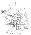
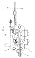
図1乃至図7は、本発明の実施形態である自動車のバックドアに用いるドアロック装置を示す。なお、従来のドアロック装置と同一部分には共通の符号を付すが、詳細な説明は省略する。また、説明の都合上、図1の状態で上下左右及び前後を定める。
【0020】
ドアロック装置はストライカ1と本体機構2を備える。ストライカ1は門形に屈曲した頑丈な部材である。本体機構2は、筺体2aの内部にストライカ1に係合するラッチ機構を納め、そのラッチレバー5がカバープレート2bの上面に配置されている。
カバープレート2bからベースプレート6が上方に直角に配置され、ベースプレート6の後面にオープンレバー12が配置されて、カバープレート2bから立設された起立片28に軸着されている(図5)。オープンレバー12の操作部12aには円弧状孔12cが穿設され、この円弧状孔12cに操作ケーブル26の先端が摺動可能に係止されている。
【0021】
ベースプレート6の前面にはクローズレバー7が配置される。クローズレバー7は、クロージャーモーター7cの回転に伴って回動するギア部材30に連結ロッド31を介して接続されている。
また、クローズレバー7はベースプレート6の前面側に軸7aによって軸着され、軸7aの下方において、クローズレバー7は上部の軸線に対して鈍角を持って屈曲し、短い取付部35が形成されている。クローズレバー7の取付部35には、その軸線に沿って長孔35aが穿設されると共に、長孔35aに摺動自在に係合されたガイド軸34aによって板状のフックレバー34が軸着されている。フックレバー34の下縁部には、かぎ状のフック部32を形成してあり、このフック部32がラッチレバー5の係合凹部33と対向している。また、フックレバー34の中央部には、ほぼ水平状にガイド長孔34bが穿設され、ガイド長孔34bの側方にフックレバーガイドピン34cが装着されている。
【0022】
ベースプレート6の下部には、フックレバー34のガイド長孔34bと摺動自在に係合する他のフックレバーガイドピン60が固着され、他のフックレバーガイドピン60の側方に、ほぼ水平状の他のガイド長孔61が穿設されている。この他のガイド長孔61にはフックレバー34のフックレバーガイドピン34cが摺動自在に係合されている。
そして、フックレバー34のガイド長孔34bとベースプレート6の他のフックレバーガイドピン60、及び、フックレバー34の他のフックレバーガイドピン34cとベースプレート6の他のガイド長孔61とは、それぞれフックレバー34を水平方向に案内するガイド手段を構成している。
【0023】
従って、図1において、クローズレバー7を軸7aを中心に回動すると、クローズレバー7の下端に軸着したフックレバー34は、2組のガイド手段に案内されて、ラッチレバー5の係合凹部33に接離するよう安定して水平移動する。
クロージャーモータ7cを作動させてクローズレバー7の上端部を右方向に回動させると、フックレバー34の下縁部に形成したかぎ状のフック部32は係合凹部33と当接する。さらにクローズレバー7を右回転させると、フック部32がラッチレバー5の先端部を押圧して、ラッチレバー5を左回転させることができる。
【0024】
クローズレバー7の駆動機構(図7)は、バックドアBDの本体機構2に近接して配置されている。駆動機構は、ベースプレート6から張り出す第2のベースプレート50を有する。
第2のベースプレート50には、中間部周縁に多数の歯を有するギア部材30の中心部が回動可能に軸着されている。ギア部材30のベースプレート6よりの端部から張り出した腕部30aの先端には連結ロッド31の一端部が軸着され、連結ロッド31の他端部はクローズレバー7の上端部に軸着されている。
ギア部材30の周縁に形成された歯は、クロージャーモータ7cにより駆動されるピニオン51と噛合している。
【0025】
第2のベースプレート50には、更にリミットスイッチ9,10が取り付けられる。リミットスイッチ9は、ギア部材30が右回転してその側縁部に当接するときにONとなるオーバーラン位置検出用であり、リミットスイッチ10は、ギア部材30が左回転してその他側縁に当接するときにONとなるクローズレバー7のニュートラル位置検出用である。これらのリミットスイッチ9,10は図外のコントローラーに接続され、クロージャーモータ7cの駆動を制御する。
【0026】
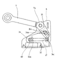
図2に示すように、クローズレバー7がニュートラル位置にある時、ガイドピン34cが他のガイド長孔61の右端に位置すると共に、他のガイドピン60がガイド長孔34bの左端に位置し、フックレバー34のフック部32はラッチレバー5から離れた位置にある。
バックドアBDが半ドア状態になると、ベースプレート6の後方に配置されたリミットスイッチ8(図6)がONとなるので、クロージャーモータ7cは正回転を開始し、ギア部材30を右回転させる。すると、ギア部材30に連結された連結ロッド31に引かれて、クローズレバー7を軸7aを中心に右回転させるため、下端に軸着したフックレバー34は、ガイド長孔34bと他のフックレバーガイドピン60、及び他のフックレバーガイドピン34cと他のガイド長孔61から成るガイド手段にガイドされて左方向に移動し、下縁部に形成したかぎ状のフック部32がラッチレバー5の係合凹部33に当接する。
【0027】
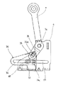
クロージャーモータ7cが正回転を継続すると、クローズレバー7は更に右回転し、フック部32がラッチレバー5をフルラッチ位置まで回動させるので、本閉め状態になる(図3)。
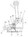
さらにクロージャーモータ7cが正回転して、クローズレバー7が図4に示すオーバーラン位置に達し、フック部32がラッチレバー5を深く押し込むと、ギア部材30の側縁部はリミットスイッチ9に当接してこれをONにするため、コントローラーはクロージャモータ7cの回転を停止し、次いで、逆回転を指令する。
クロージャーモータ7cの逆回転によってギア部材30は逆転し、これに伴ってクローズレバー7は今度は左方向に回転し、ギア部材30の他側縁がリミットスイッチ10に当接してこれをONにする。この結果、クロージャーモータ7cの駆動は停止し、クローズレバー7はニュートラル位置に戻る。同時に、フックレバー34は逆方向に水平移動して、そのフック部32がラッチレバー5から外れる。
【0028】
本閉め状態において、オープンレバー12の操作部12aに接続された操作ケーブル26を引くと、オープンレバー12の作用部12bはディテントレバー11の当接片22を回動させるので、ディテントレバー11とラッチ3との係合が解除され、一挙にフルオープン位置に戻り、バックドアBDを開くことが出来る。
また、操作ケーブル26を戻すと、オープンレバー12はディテントレバー11を付勢している第2のコイルバネ21の付勢によって右回転する。
なお、本発明のドアロック装置は、自動車のバックドア以外のドアをロックする装置とすることもできる。
【0029】
【発明の効果】
発明によれば、フックレバーのフック部が2組のガイド手段に案内されて、常にラッチレバーの係合面に対して平行状態を維持して移動し、回動することがないので、ラッチレバー或いはフックレバーががたついても両者が食い込んで作動不能となる心配がない。
また、ガイド手段を構成するのに、フックレバーガイドピンを取り付けると共に、水平状のガイド長孔を形成するだけで済むので、特別な部材や面倒な加工が不要であって、コストを低く抑えることができる。
【図面の簡単な説明】
【図1】本発明の実施形態を示すドアロック装置の正面図
【図2】ニュートラル状態におけるクローズレバー、フックレバー及びベースプレートの正面図
【図3】フルラッチ状態におけるクローズレバー、フックレバー及びベースプレートの正面図
【図4】オーバーラン状態におけるクローズレバー、フックレバー及びベースプレートの正面図
【図5】ドアロック装置の一部破断側面図
【図6】ドアロック装置の平面図
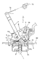
【図7】クローズレバーを駆動する駆動機構の正面図
【図8】従来のドアロック装置の正面図
【図9】従来のドアロック装置のクローズレバー及びオープンレバーの動きを示す正面図
【図10】ラッチレバーの平面図
【図11】フルオープン状態のラッチ及びディテントレバーの平面図
【図12】ハーフラッチ状態のラッチ及びディテントレバーの平面図
【図13】フルラッチ状態のラッチ及びディテントレバーの平面図
【符号の説明】
1 ストライカ
2 本体機構
2a 筺体
2b カバープレート
3 ラッチ
4 シャフト
5 ラッチレバー
6 ベースプレート
7 クローズレバー
7a 軸
7b ギヤドワイヤ
7c クロージャーモータ
8 ハーフラッチ位置検出用リミットスイッチ
9 オーバーラン位置検出用リミットスイッチ
10 ニュートラル位置検出用リミットスイッチ
11 ディテントレバー
12 オープンレバー
12a 操作部
12b 作用部
12c 円弧状孔
13 切欠
14 フランジ
15 ストライカ進入口
16 開口部
17 第1のコイルバネ
18 第1の段部
19 第2の段部
20 係止突起
21 第2のコイルバネ
22 当接片
23 案内孔
24 第1の軸
25 軸
26 操作ケーブル
28 起立片
30 ギア部材
30a 腕部
31 連結ロッド
32 フック部
33 係合凹部
34 フックレバー
34a ガイド軸
34b ガイド長孔
34c フックレバーガイドピン
35 取付部
35a 長孔
50 第2のベースプレート
51 ピニオン
60 他のフックレバーガイドピン
61 他のガイド長孔
[0001]
BACKGROUND OF THE INVENTION
The present invention relates to a door lock device, and more particularly to a device suitable for locking a back door or the like of an automobile.
[0002]
[Prior art]
Conventionally, it is not necessary to automatically move from the half-door state so that it is safe for a car to run with the half-door state of the back door, or to prevent the back door from colliding with the vehicle body side and making it fully closed. A door lock device that shifts to the fully closed state is known.
The conventional door lock device will be described with reference to FIGS. 8 to 13, and since it has the same mechanism as the present invention in many respects, it will be described in detail as a premise of the present invention.
[0003]
As shown in FIG. 8, a striker 1 bent in a gate shape is fixed to the lower edge of the rear opening of the automobile.
A main body mechanism 2 of a door lock device is attached to the back door BD of the automobile. The main body mechanism 2 has a housing 2a exposed to the outside on the lower surface of the back door BD, a cover plate 2b that covers the upper surface of the housing 2a (when attached), and a cover plate 2b that projects upward at a right angle to form a back door structure. A base plate 6 serving as a base is provided so as to protrude inside. These are firmly constructed of thick plates, and are securely integrated by welding after attaching each member described later. Note that flanges 14 for bolting the main body mechanism 2 to the lower surface of the back door BD are provided on both sides of the housing 2a and the cover plate 2b.
[0004]
A latch 3 and a detent lever 11 are pivotally supported by a shaft 4 and a shaft 11a in a substantially vertical direction in a housing portion formed by the housing 2a and the cover plate 2b, and the latch 3 is supported by a first coil spring 17. In FIG. 11, the detent lever 11 is constantly urged in the left rotation direction by the second coil spring 21.
The latch 3 includes a first step portion 18 and a second step portion 19 and includes a notched portion 13 that is greatly hollowed out. The notch 13 has a width and a depth for receiving the striker 1. Further, the notch 13 has a contact surface 15a on the side of the second stepped portion 19 and crosses the striker entrance 15 toward the front of the housing 2a when the latch 3 is fully opened (in the state shown in FIG. 11). positioned.
[0005]
The detent lever 11 has a bifurcated portion on the opposite side to the opening side of the striker entrance 15, one side on the latch 3 side is a locking projection 20, and the latch 3 is always latched by the bias of the second coil spring 21. The other is a contact piece 22. The latching protrusion 20 allows the latch 3 to rotate left, but when it falls into the first step 18 and the second step 19, it opposes the bias of the first coil spring 17 and the latch 3 rotates right. To stop doing. However, when a force is applied to the contact piece 22 to rotate it to the right, the engagement between the locking projection 20 and the first and second step portions 18 and 19 can be released.
[0006]
The shaft 4 of the latch 3 extends beyond the cover plate 2b to the inside of the back door BD, and a latch lever 5 is fixed to the tip thereof. Accordingly, the latch lever 5 is integrated with the latch 3 and reversibly rotates from the full open position a to the overrun position d via the half latch position b and the full latch position c, as shown in FIG. .
A limit switch 8 is attached to the cover plate 2b with an opening 16 formed in the base plate 6 interposed therebetween. This switch 8 is for detecting the half latch position (half door state).
[0007]
As shown in FIGS. 8 and 9, a close lever 7 is attached to the front surface of the base plate 6 by a shaft 7 a so as to rotate between stoppers 6 a and 6 b provided on the base plate 6.
The close lever 7 is formed in an elongated hook shape, and a hook portion 32 that is curved toward the latch lever 5 is formed at the lower end thereof. The upper end of the close lever 7 is an attachment portion for the geared wire 7b pushed and pulled by the closure motor 7c. Yes.
The hook portion 32 formed on the lower end portion of the close lever 7 faces the engagement recess 33 formed on the side surface of the latch lever 5, and when the close lever 7 rotates to the right, the latch lever 5 is rotated to the left.
[0008]
Limit switches 9 and 10 are attached to the front surface of the base plate 6. The limit switch 9 is for detecting a latch position that is turned on when the close lever 7 rotates clockwise in FIG. 8 and comes into contact with the stopper 6b. The limit switch 10 rotates to the left when the close lever 7 rotates counterclockwise. This is for detecting the latch position that is turned ON when touching. These limit switches 8, 9, and 10 are connected to a controller (not shown) and control the drive of the closure motor.
[0009]
The open lever 12 is pivotally mounted on the rear side of the base plate 6 so that the open lever 12 can pivot. The open lever 12 has an operation portion 12a located inside the structure constituting the back door BD and an action extending downward from the shaft 25. A portion 12b is formed. The action portion 12 b enters the inside of the housing 2 a and engages with the contact piece 22 of the detent lever 11.
Then, as shown in FIG. 9, when the operating portion 12a is pushed and the open lever 12 is rotated to the left, the operating portion is moved to the right to rotate the contact piece 22 of the detent lever 11, and the latch 3 And the detent lever 11 can be disengaged.
[0010]
In a state where the back door BD is opened, the latch 3 of the door lock device is in the full open position shown in FIG. When the back door BD is closed, the contact surface 15a of the latch 3 collides with the striker 1 and rotates to the left in the drawing. With the rotation, the notch 13 of the latch 3 holds the striker 1 and the locking projection 20 of the detent lever 11 is engaged with the first step portion 18 (FIG. 12). In this state, the latch 3 is temporarily engaged with the striker 1, and the latch 3 cannot be rotated in the reverse direction (right rotation) due to the engagement between the detent lever 11 and the first step portion 18, so that the door opens. There is nothing. However, it is in a so-called half-door state in which the closed state is unstable.
[0011]
When the latch 3 is rotated to the half door state, the latch lever 5 is also rotated and the limit switch 8 is turned on. As a result, the closure motor 7c rotates and rotates the close lever 7 to the right through the geared wire until it contacts the stopper 6b in FIG. Then, since the hook part 32 which is the front-end | tip part of the close lever 7 rotates the latch lever 5 counterclockwise, when it sees from the outside, the latch 3 will further rotate counterclockwise and will be in the full latch state of FIG. That is, the striker 1 is completely fitted in the back of the notch 15 of the latch 3, and the locking protrusion 20 of the detent lever 11 is engaged with the second step portion 19 of the latch 3 to reversely rotate the latch 3. The blocked book is closed.
[0012]
The close lever 7 rotated until it comes into contact with the stopper 6b turns on the limit switch 9, and the controller stops the forward rotation of the closure motor 7c, and then commands the reverse rotation. Due to the reverse rotation of the closure motor 7c, the close lever 7 is now rotated counterclockwise until it contacts the stopper 6a on the opposite side, and the limit switch 10 is turned ON. As a result, the drive of the closure motor is stopped, the close lever 7 returns to the neutral position, and the hook portion 32 is disengaged from the latch lever 5.
Each limit switch 8, 9, 10 is turned off when the latch lever 5 or the close lever 7 is released, and waits for the next ON operation. When the latch 3 is at the full latch position, the limit switch 8 is OFF. Even if the latch lever 5 is free from the close lever 7, the latch 3 cannot be freely rotated because it is engaged with the detent lever 11.
[0013]
When opening the back door BD, the operation part 12a of the open lever 12 is pushed downward. Then, the open lever 12 rotates counterclockwise, the tip of the action portion 12b pushes the contact piece 22 of the detent lever 11, and the engagement between the locking projection 20 and the second step portion 19 of the latch 3 is released. The latch 3 is pivoted to the open position energized by the first coil spring 17, and the back door BD and the vehicle body are unlocked.
[0014]
[Problems to be solved by the invention]
As described above, the conventional door lock device shifts from the half-door state to the fully closed state using the closure motor 7c, so that it is not necessary to close the door roughly and avoid the risk of opening the door during traveling. To improve safety.
[0015]
However, in the above conventional door lock device, the close lever 7 is rotated and the hook portion 32 at the tip thereof is locked to the latch lever 5, so that the close lever 7 swings back and forth so as to intersect the rotation surface. If it is inclined or the latch lever 5 rattles, the hook portion 32 rides on the upper surface of the latch lever 5 and does not move. If such a situation occurs, there is a possibility that the back door BD cannot be opened and closed or the closure motor 7c is damaged.
In particular, in an emergency vehicle such as an ambulance, the back door BD is vigorously shaken up and down during the automatic progress from the half door state to the fully closed state in order to confirm the closed state of the back door BD. 5 and the close lever 7 rattle and are easy to bite.
[0016]
The present invention improves the drawbacks of the conventional door lock device, prevents biting between the latch lever and the hook portion engaged with the latch lever, can ensure smooth opening and closing of the door, and has a simple structure. It is to provide a locking device.
[0017]
[Means for Solving the Problems]
The door lock device of the present invention has the same basic structure as that of the conventional door lock device. However, the door lock device has a long hole 35a formed along the axis below the shaft attaching portion of the close lever 7, and a long hole. A hook lever 34 is pivotally attached via a guide shaft 34a slidably engaged with 35a, and is attached to a horizontal guide long hole 34b formed in the hook lever 34 and the base plate 6 of the main body mechanism 2. One guide means comprising a hook lever guide pin 60 slidably engaged with the guide elongated hole 34b of the hook lever 34, and a horizontal guide elongated hole 61 formed in the base plate 6 of the main body mechanism 2. When, is mounted on the hook lever 34, by providing the other guide means consisting of a hook lever guide pin 34c slidably engages the guide slot 61 of the base plate 6, As the rose lever 7 rotates, the hook lever 34 moves horizontally in the direction of contact with and away from the latch lever 5, and the latch lever 5 is pressed and rotated by the hook portion 32, thereby releasing the latch 3 in the half door state. rotates the closed state, further, Ru tare as then returns to its original position out of the latch lever 5.
According to the door lock device of the present invention, the hook portion 32 of the hook lever 34 that engages with the latch lever 5 is guided by the two sets of guide means and always maintains a parallel state with respect to the engaging surface of the latch lever 5. Therefore, the latch lever 5 does not bite like the hook portion that rotates, and therefore the door can be smoothly opened and closed.
[0019]
DETAILED DESCRIPTION OF THE INVENTION
1 to 7 show a door lock device used for a back door of an automobile according to an embodiment of the present invention. In addition, although the same code | symbol is attached | subjected to the same part as the conventional door lock apparatus, detailed description is abbreviate | omitted. For convenience of explanation, the top / bottom / left / right and front / back are defined in the state of FIG.
[0020]
The door lock device includes a striker 1 and a main body mechanism 2. The striker 1 is a sturdy member bent in a gate shape. The main body mechanism 2 houses a latch mechanism that engages with the striker 1 inside the housing 2a, and the latch lever 5 is disposed on the upper surface of the cover plate 2b.
The base plate 6 is disposed at a right angle upward from the cover plate 2b, the open lever 12 is disposed on the rear surface of the base plate 6, and is pivotally attached to the upright piece 28 erected from the cover plate 2b (FIG. 5). An arc-shaped hole 12c is formed in the operation portion 12a of the open lever 12, and the tip of the operation cable 26 is slidably locked in the arc-shaped hole 12c.
[0021]
A close lever 7 is disposed on the front surface of the base plate 6. The close lever 7 is connected via a connecting rod 31 to a gear member 30 that rotates as the closure motor 7c rotates.
The close lever 7 is pivotally attached to the front side of the base plate 6 by a shaft 7a, and below the shaft 7a, the close lever 7 is bent at an obtuse angle with respect to the upper axis, and a short mounting portion 35 is formed. Yes. The mounting portion 35 of the close lever 7 is provided with a long hole 35a along the axis thereof, and a plate-like hook lever 34 is pivotally attached by a guide shaft 34a slidably engaged with the long hole 35a. Has been. A hook-shaped hook portion 32 is formed at the lower edge portion of the hook lever 34, and the hook portion 32 faces the engagement recess 33 of the latch lever 5. In addition, a guide long hole 34b is formed in a substantially horizontal shape at the center of the hook lever 34, and a hook lever guide pin 34c is attached to the side of the guide long hole 34b.
[0022]
Another hook lever guide pin 60 slidably engaged with the guide elongated hole 34 b of the hook lever 34 is fixed to the lower portion of the base plate 6, and a substantially horizontal shape is formed on the side of the other hook lever guide pin 60. Another guide slot 61 is formed. A hook lever guide pin 34c of the hook lever 34 is slidably engaged with the other guide slot 61.
The guide long hole 34b of the hook lever 34 and the other hook lever guide pin 60 of the base plate 6 and the other hook lever guide pin 34c of the hook lever 34 and the other guide long hole 61 of the base plate 6 are respectively hooks. Guide means for guiding the lever 34 in the horizontal direction is configured.
[0023]
Therefore, in FIG. 1, when the close lever 7 is rotated about the shaft 7a, the hook lever 34 pivotally attached to the lower end of the close lever 7 is guided by the two sets of guide means, and the engagement recess of the latch lever 5 is engaged. It moves horizontally so as to be in contact with and away from 33.
When the closure motor 7 c is operated and the upper end portion of the close lever 7 is rotated rightward, the hook-shaped hook portion 32 formed on the lower edge portion of the hook lever 34 comes into contact with the engaging recess 33. When the close lever 7 is further rotated to the right, the hook portion 32 presses the tip of the latch lever 5 and the latch lever 5 can be rotated to the left.
[0024]
The drive mechanism (FIG. 7) of the close lever 7 is disposed in the vicinity of the main body mechanism 2 of the back door BD. The drive mechanism includes a second base plate 50 that projects from the base plate 6.
A center portion of the gear member 30 having a large number of teeth on the periphery of the intermediate portion is pivotally attached to the second base plate 50 so as to be rotatable. One end of the connecting rod 31 is pivotally attached to the tip of the arm portion 30 a that protrudes from the end of the gear member 30 from the base plate 6, and the other end of the connecting rod 31 is pivotally attached to the upper end of the close lever 7. Yes.
The teeth formed on the periphery of the gear member 30 mesh with the pinion 51 driven by the closure motor 7c.
[0025]
Limit switches 9 and 10 are further attached to the second base plate 50. The limit switch 9 is for detecting an overrun position that is turned on when the gear member 30 rotates to the right and comes into contact with the side edge. The limit switch 10 rotates to the other side edge when the gear member 30 rotates to the left. This is for detecting the neutral position of the close lever 7 that is turned on when it comes into contact. These limit switches 9 and 10 are connected to a controller (not shown) and control the drive of the closure motor 7c.
[0026]
As shown in FIG. 2, when the close lever 7 is in the neutral position, the guide pin 34c is positioned at the right end of the other guide slot 61, and the other guide pin 60 is positioned at the left end of the guide slot 34b. The hook portion 32 of the hook lever 34 is located away from the latch lever 5.
When the back door BD is in a half-door state, the limit switch 8 (FIG. 6) disposed on the rear side of the base plate 6 is turned on, so the closure motor 7c starts normal rotation and rotates the gear member 30 to the right. Then, the hook lever 34 pivotally attached to the lower end is pulled by the connecting rod 31 connected to the gear member 30 to rotate the close lever 7 clockwise around the shaft 7a. Guided by a guide means comprising a guide pin 60 and another hook lever guide pin 34c and another guide elongated hole 61, it moves to the left, and a hook-like hook portion 32 formed at the lower edge portion of the latch lever 5 It contacts the engaging recess 33.
[0027]
When the closure motor 7c continues to rotate forward, the close lever 7 rotates further to the right, and the hook portion 32 rotates the latch lever 5 to the full latch position, so that it is in the fully closed state (FIG. 3).
Further, when the closure motor 7c rotates forward, the close lever 7 reaches the overrun position shown in FIG. 4, and the hook portion 32 pushes the latch lever 5 deeply, the side edge portion of the gear member 30 comes into contact with the limit switch 9. In order to turn this on, the controller stops the rotation of the closure motor 7c and then commands reverse rotation.
The gear member 30 is reversely rotated by the reverse rotation of the closure motor 7c, and the close lever 7 is now rotated to the left, and the other side edge of the gear member 30 contacts the limit switch 10 to turn it ON. . As a result, the drive of the closure motor 7c stops and the close lever 7 returns to the neutral position. At the same time, the hook lever 34 moves horizontally in the opposite direction, and the hook portion 32 is released from the latch lever 5.
[0028]
In the fully closed state, when the operation cable 26 connected to the operation portion 12a of the open lever 12 is pulled, the action portion 12b of the open lever 12 rotates the contact piece 22 of the detent lever 11, so that the detent lever 11 and the latch are latched. 3 is released, and the back door BD can be opened by returning to the full open position all at once.
When the operation cable 26 is returned, the open lever 12 rotates to the right by the bias of the second coil spring 21 that biases the detent lever 11.
The door lock device of the present invention can also be a device that locks a door other than the back door of an automobile.
[0029]
【The invention's effect】
According to the present invention, the hook portion of the hook lever is guided by the two sets of guide means and always moves while maintaining a parallel state with respect to the engaging surface of the latch lever, so that it does not rotate. Even if the lever or the hook lever rattles, there is no concern that both will bite and become inoperable.
In addition , it is only necessary to install a hook lever guide pin and to form a horizontal guide elongated hole to configure the guide means, so that no special member or troublesome processing is required, and the cost can be kept low. Can do.
[Brief description of the drawings]
FIG. 1 is a front view of a door lock device showing an embodiment of the present invention. FIG. 2 is a front view of a close lever, hook lever and base plate in a neutral state. FIG. 3 is a front view of a close lever, hook lever and base plate in a full latch state. [Fig. 4] Front view of close lever, hook lever and base plate in overrun state [Fig. 5] Partially cutaway side view of door lock device [Fig. 6] Plan view of door lock device [Fig. 7] Drive close lever FIG. 8 is a front view of a conventional door lock device. FIG. 9 is a front view showing the movement of a closing lever and an open lever of the conventional door lock device. FIG. 10 is a plan view of a latch lever. 11] Plan view of latch and detent lever in full open state [Fig. 12] Latch in half latch state Plan view of the fine detent lever 13 is a plan view of the latch and the detent lever of the fully-latched state EXPLANATION OF REFERENCE NUMERALS
1 striker 2 body mechanism 2a housing 2b cover plate 3 latch 4 shaft 5 latch lever 6 base plate 7 close lever 7a shaft 7b geared wire 7c closure motor 8 half latch position detection limit switch 9 overrun position detection limit switch 10 neutral position detection Limit switch 11 Detent lever 12 Open lever 12a Operation portion 12b Action portion 12c Arc-shaped hole 13 Notch 14 Flange 15 Strike advance 16 Opening portion 17 First coil spring 18 First step portion 19 Second step portion 20 Locking projection 21 Second coil spring 22 Contact piece 23 Guide hole 24 First shaft 25 Shaft 26 Operation cable 28 Standing piece 30 Gear member 30a Arm portion 31 Connecting rod 32 Hook portion 33 Engaging recess 34 Hook lever 34a Guide shaft 4b guide slot 34c hook lever guide pin 35 mounting portion 35a long hole 50 second baseplate 51 pinion 60 other hook lever guide pin 61 another guide slot

Claims (1)

ドア又はドア支持体の一方に設けられたストライカ1と、他方に設けられてストライカ1と係脱自在に係合する本体機構2とからなり、本体機構2は、半ドア状態を経て本閉め状態に回動することによりストライカ1と完全に係合するラッチ3と、ラッチ3と連動するラッチレバー5と、ラッチレバー5に係脱するフック部32を有するフックレバー34と、本体機構2のベースプレート6に軸着され、その下端にフックレバー34の端部を回動可能に軸着したクローズレバー7と、その回動操作によってラッチ3をオープン方向へ回動させるオープンレバー12とを具備し、クローズレバー7はクロージャーモータによって回動され、クローズレバー7の軸着部よりも下部に軸線に沿って長孔35aを穿設すると共に、長孔35aに摺動自在に係合したガイド軸34aを介してフックレバー34を軸着し、フックレバー34に穿設された水平状のガイド長孔34bと、本体機構2のベースプレート6に装着されて、フックレバー34のガイド長孔34bに摺動自在に係合するフックレバーガイドピン60とから成る一方のガイド手段、及び、本体機構2のベースプレート6に穿設された水平状のガイド長孔61と、フックレバー34に装着されて、ベースプレート6のガイド長孔61に摺動自在に係合するフックレバーガイドピン34cとから成る他方のガイド手段を設けることにより、フックレバー34は、クローズレバー7の回動に伴ってラッチレバー5に接離する方向に水平移動して、そのフック部32でラッチレバー5を押圧回動することにより半ドア状態のラッチ3を本閉め状態に回動し、さらに、その後ラッチレバー5から外れた元の位置に戻ることを特徴とするドアロック装置。It consists of a striker 1 provided on one of the door or the door support and a main body mechanism 2 provided on the other side and detachably engaged with the striker 1, and the main body mechanism 2 is in a fully closed state through a half-door state. , A latch 3 that is completely engaged with the striker 1, a latch lever 5 that is interlocked with the latch 3, a hook lever 34 that has a hook portion 32 that engages and disengages with the latch lever 5, and a base plate of the main body mechanism 2. 6, and a close lever 7 pivotally attached to the lower end of the hook lever 34 at its lower end, and an open lever 12 for turning the latch 3 in the open direction by the turning operation. closing lever 7 is rotated by a closure motor, along the axis at the bottom than the shaft attaching portion of the closing lever 7 with bored long holes 35a, sliding own in the long hole 35a A hook lever 34 is pivotally attached via a guide shaft 34 a engaged with the hook lever 34, and is attached to a horizontal guide long hole 34 b drilled in the hook lever 34 and the base plate 6 of the main body mechanism 2. One guide means including a hook lever guide pin 60 slidably engaged with the guide long hole 34b, a horizontal guide long hole 61 formed in the base plate 6 of the main body mechanism 2, and the hook lever 34 The hook lever 34 is attached to the base plate 6 and slidably engages with the guide elongated hole 61 of the base plate 6 so that the hook lever 34 is rotated with the rotation of the close lever 7. The latch 3 is moved horizontally in the direction of contact with and away from the latch lever 5, and the latch lever 5 is pressed and rotated by the hook portion 32, thereby releasing the latch 3 in the half door state. Pivots closed state, further, the door lock device comprising a Turkey return to subsequent original position out of the latch lever 5.
JP2000005788A 2000-01-06 2000-01-06 Door lock device Expired - Fee Related JP4354603B2 (en)

Priority Applications (1)

Application Number Priority Date Filing Date Title
JP2000005788A JP4354603B2 (en) 2000-01-06 2000-01-06 Door lock device

Applications Claiming Priority (1)

Application Number Priority Date Filing Date Title
JP2000005788A JP4354603B2 (en) 2000-01-06 2000-01-06 Door lock device

Publications (2)

Publication Number Publication Date
JP2001193328A JP2001193328A (en) 2001-07-17
JP4354603B2 true JP4354603B2 (en) 2009-10-28

Family

ID=18534409

Family Applications (1)

Application Number Title Priority Date Filing Date
JP2000005788A Expired - Fee Related JP4354603B2 (en) 2000-01-06 2000-01-06 Door lock device

Country Status (1)

Country Link
JP (1) JP4354603B2 (en)

Families Citing this family (4)

* Cited by examiner, † Cited by third party
Publication number Priority date Publication date Assignee Title
KR100654065B1 (en) 2005-11-04 2006-12-06 평화정공 주식회사 Motorized Restraint Structure for Automotive Tailgate Latches
KR101171921B1 (en) 2010-04-29 2012-08-08 고등기술연구원연구조합 Electromotive gate latch system
JP6346073B2 (en) * 2014-11-25 2018-06-20 アイシン機工株式会社 Vehicle door lock device
CN116220482B (en) * 2023-03-20 2024-04-26 一汽解放汽车有限公司 Integrated vehicle door lock and vehicle

Also Published As

Publication number Publication date
JP2001193328A (en) 2001-07-17

Similar Documents

Publication Publication Date Title
US7399010B2 (en) Power-actuated motor-vehicle door latch with quick unlock
JP4473919B2 (en) Door latch device for automobile
JP3835606B2 (en) Electric lock
KR20210021658A (en) Power child lock device
JPH0223670B2 (en)
JP4354603B2 (en) Door lock device
JP4345432B2 (en) Vehicle door latch mechanism
JPH116346A (en) Locking/unlocking device of door body
JP3390650B2 (en) Door locking and unlocking device
JP3886473B2 (en) Door auto closure
JP4227684B2 (en) Door lock device
JP4351318B2 (en) Door lock device
JP3673986B2 (en) Door lock device for automobile
JP3149367B2 (en) Latch device for hatched vehicle back door
JP3433371B2 (en) Electric closing device of opening and closing body
JP4559603B2 (en) Car trunk lid lock device
JPH0573874B2 (en)
JP7435220B2 (en) Vehicle hood lock system
JPS5834942Y2 (en) Door lock lock/unlock operation device
JP3390651B2 (en) Door locking and unlocking device
JP3458070B2 (en) Door lock device
JPH11159212A (en) Door locking device for vehicle
JP2001277855A (en) Stopper mechanism for slide door
JP2002038795A (en) Door lock device for automobile
JPS5830474B2 (en) Door lock lock/unlock operation device

Legal Events

Date Code Title Description
A621 Written request for application examination

Free format text: JAPANESE INTERMEDIATE CODE: A621

Effective date: 20061211

A977 Report on retrieval

Free format text: JAPANESE INTERMEDIATE CODE: A971007

Effective date: 20090402

A131 Notification of reasons for refusal

Free format text: JAPANESE INTERMEDIATE CODE: A131

Effective date: 20090602

A521 Written amendment

Free format text: JAPANESE INTERMEDIATE CODE: A523

Effective date: 20090701

TRDD Decision of grant or rejection written
A01 Written decision to grant a patent or to grant a registration (utility model)

Free format text: JAPANESE INTERMEDIATE CODE: A01

Effective date: 20090728

A01 Written decision to grant a patent or to grant a registration (utility model)

Free format text: JAPANESE INTERMEDIATE CODE: A01

A61 First payment of annual fees (during grant procedure)

Free format text: JAPANESE INTERMEDIATE CODE: A61

Effective date: 20090730

R150 Certificate of patent (=grant) or registration of utility model

Free format text: JAPANESE INTERMEDIATE CODE: R150

FPAY Renewal fee payment (prs date is renewal date of database)

Free format text: PAYMENT UNTIL: 20120807

Year of fee payment: 3

FPAY Renewal fee payment (prs date is renewal date of database)

Free format text: PAYMENT UNTIL: 20130807

Year of fee payment: 4

LAPS Cancellation because of no payment of annual fees