JP4355277B2 - ケーブル式ステアリング装置 - Google Patents
ケーブル式ステアリング装置 Download PDFInfo
- Publication number
- JP4355277B2 JP4355277B2 JP2004336279A JP2004336279A JP4355277B2 JP 4355277 B2 JP4355277 B2 JP 4355277B2 JP 2004336279 A JP2004336279 A JP 2004336279A JP 2004336279 A JP2004336279 A JP 2004336279A JP 4355277 B2 JP4355277 B2 JP 4355277B2
- Authority
- JP
- Japan
- Prior art keywords
- steering
- tension
- cable
- pulley
- driven pulley
- Prior art date
- Legal status (The legal status is an assumption and is not a legal conclusion. Google has not performed a legal analysis and makes no representation as to the accuracy of the status listed.)
- Expired - Fee Related
Links
Images

Landscapes
- Power Steering Mechanism (AREA)
- Steering Controls (AREA)
Description
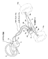
2 ハンドル(ステアリングハンドル)
4 駆動プーリハウジング
5 ステアリングギアボックス
6 従動プーリハウジング
7,8 ボーデンケーブル(操作ケーブル)
7b,8b インナーケーブル
10a,10b 転舵車輪
12 駆動プーリ
15 張力調整装置(張力調整手段)
16a,16b ローラ部材
18a,18b 支持板
21 コイルばね
23 ダンパー装置(減衰力発生手段)
23a ピストンロッド
25 従動プーリ
Claims (1)
- ステアリングハンドル側に連結されて回転する駆動プーリと、転舵車輪を転舵するステアリングギアボックス側に連結されて回転する従動プーリと、前記駆動プーリの回転を前記従動プーリに伝達する操作ケーブルとを備えてなり、前記操作ケーブルは、前記駆動プーリを収納する駆動プーリハウジングに一端を支持されるとともに、前記従動プーリを収納する従動プーリハウジングに他端を支持された一対のアウター部材と、前記各アウター部材の内部に摺動自在に挿通され、張力を付与した状態で両端が前記駆動プーリと前記従動プーリにそれぞれ巻き付けられて固定された一対のインナーケーブルとから構成されたケーブル式ステアリング装置において、
前記一対のインナーケーブルに揺動自在に当接して、設定した所定張力を保持するように直接張力を付与する張力調整手段と、
前記張力調整手段に揺動自在に接続した減衰力発生手段とを有し、
前記減衰力発生手段は、前記ステアリングハンドルに入力された操舵トルクで前記一対のインナーケーブルの張力が前記所定張力より増加したときにおける前記張力調整手段の揺動に対して減衰力を発生させる、
ことを特徴とするケーブル式ステアリング装置。
Priority Applications (1)
| Application Number | Priority Date | Filing Date | Title |
|---|---|---|---|
| JP2004336279A JP4355277B2 (ja) | 2004-11-19 | 2004-11-19 | ケーブル式ステアリング装置 |
Applications Claiming Priority (1)
| Application Number | Priority Date | Filing Date | Title |
|---|---|---|---|
| JP2004336279A JP4355277B2 (ja) | 2004-11-19 | 2004-11-19 | ケーブル式ステアリング装置 |
Publications (2)
| Publication Number | Publication Date |
|---|---|
| JP2006143007A JP2006143007A (ja) | 2006-06-08 |
| JP4355277B2 true JP4355277B2 (ja) | 2009-10-28 |
Family
ID=36623187
Family Applications (1)
| Application Number | Title | Priority Date | Filing Date |
|---|---|---|---|
| JP2004336279A Expired - Fee Related JP4355277B2 (ja) | 2004-11-19 | 2004-11-19 | ケーブル式ステアリング装置 |
Country Status (1)
| Country | Link |
|---|---|
| JP (1) | JP4355277B2 (ja) |
-
2004
- 2004-11-19 JP JP2004336279A patent/JP4355277B2/ja not_active Expired - Fee Related
Also Published As
| Publication number | Publication date |
|---|---|
| JP2006143007A (ja) | 2006-06-08 |
Similar Documents
| Publication | Publication Date | Title |
|---|---|---|
| JP4305429B2 (ja) | インホイールサスペンション | |
| KR101126248B1 (ko) | 스티어 바이 와이어 장치 | |
| JP3888607B2 (ja) | 電動パワーステアリング装置 | |
| JP3934925B2 (ja) | ケーブル式ステアリング装置 | |
| JP4403583B2 (ja) | ダイナミックダンパー機構 | |
| JP2006143007A (ja) | ケーブル式ステアリング装置 | |
| US5937704A (en) | Cable-type steering device | |
| JP3966622B2 (ja) | ケーブル式ステアリング装置における操舵角検出装置 | |
| JP2007069868A (ja) | ステアリング装置のシャフトジョイント構造及びステアリング装置 | |
| JP4696687B2 (ja) | ステアリング装置 | |
| KR20080039596A (ko) | 전동식 파워 스티어링 장치의 웜축 유격보상장치 | |
| JP4278523B2 (ja) | ポテンショメータの取付け部材 | |
| JP2000280923A (ja) | 電動パワーステアリング装置 | |
| JP5434250B2 (ja) | 車両用ステアリングダンパ装置及びステアリング装置 | |
| JPS6146343B2 (ja) | ||
| JP4454800B2 (ja) | 電動パワーステアリング装置 | |
| JP2008074260A (ja) | センターテイクオフ型ステアリング装置 | |
| JP5050586B2 (ja) | 車両用操舵装置 | |
| KR20100032611A (ko) | 자동차 조향장치의 슬립 조인트 | |
| JP3966859B2 (ja) | ケーブル式ステアリング装置 | |
| KR100356841B1 (ko) | 자동차용 조향링키지의 구조 | |
| JP5772042B2 (ja) | ステアリング装置 | |
| JP4523349B2 (ja) | ケーブル式操作装置およびケーブル式ステアリング装置 | |
| JP2002340017A (ja) | ジョイント機構及びそれを用いた操舵補助装置 | |
| JP2007216835A (ja) | ケーブル式操舵装置、自動車及びケーブル式操舵装置の制御方法 |
Legal Events
| Date | Code | Title | Description |
|---|---|---|---|
| A621 | Written request for application examination |
Effective date: 20061128 Free format text: JAPANESE INTERMEDIATE CODE: A621 |
|
| A977 | Report on retrieval |
Free format text: JAPANESE INTERMEDIATE CODE: A971007 Effective date: 20081226 |
|
| TRDD | Decision of grant or rejection written | ||
| A01 | Written decision to grant a patent or to grant a registration (utility model) |
Free format text: JAPANESE INTERMEDIATE CODE: A01 Effective date: 20090728 |
|
| A01 | Written decision to grant a patent or to grant a registration (utility model) |
Free format text: JAPANESE INTERMEDIATE CODE: A01 |
|
| A61 | First payment of annual fees (during grant procedure) |
Free format text: JAPANESE INTERMEDIATE CODE: A61 Effective date: 20090731 |
|
| R150 | Certificate of patent (=grant) or registration of utility model |
Free format text: JAPANESE INTERMEDIATE CODE: R150 |
|
| FPAY | Renewal fee payment (prs date is renewal date of database) |
Year of fee payment: 3 Free format text: PAYMENT UNTIL: 20120807 |
|
| LAPS | Cancellation because of no payment of annual fees |