JP4356548B2 - 基板用コネクタ - Google Patents
基板用コネクタ Download PDFInfo
- Publication number
- JP4356548B2 JP4356548B2 JP2004211855A JP2004211855A JP4356548B2 JP 4356548 B2 JP4356548 B2 JP 4356548B2 JP 2004211855 A JP2004211855 A JP 2004211855A JP 2004211855 A JP2004211855 A JP 2004211855A JP 4356548 B2 JP4356548 B2 JP 4356548B2
- Authority
- JP
- Japan
- Prior art keywords
- terminal
- main body
- fitting
- reinforcing
- relay
- Prior art date
- Legal status (The legal status is an assumption and is not a legal conclusion. Google has not performed a legal analysis and makes no representation as to the accuracy of the status listed.)
- Expired - Lifetime
Links
Images


Classifications
-
- H—ELECTRICITY
- H01—ELECTRIC ELEMENTS
- H01R—ELECTRICALLY-CONDUCTIVE CONNECTIONS; STRUCTURAL ASSOCIATIONS OF A PLURALITY OF MUTUALLY-INSULATED ELECTRICAL CONNECTING ELEMENTS; COUPLING DEVICES; CURRENT COLLECTORS
- H01R13/00—Details of coupling devices of the kinds covered by groups H01R12/70 or H01R24/00 - H01R33/00
- H01R13/46—Bases; Cases
- H01R13/502—Bases; Cases composed of different pieces
- H01R13/504—Bases; Cases composed of different pieces different pieces being moulded, cemented, welded, e.g. ultrasonic welding, or swaged together
-
- H—ELECTRICITY
- H01—ELECTRIC ELEMENTS
- H01R—ELECTRICALLY-CONDUCTIVE CONNECTIONS; STRUCTURAL ASSOCIATIONS OF A PLURALITY OF MUTUALLY-INSULATED ELECTRICAL CONNECTING ELEMENTS; COUPLING DEVICES; CURRENT COLLECTORS
- H01R12/00—Structural associations of a plurality of mutually-insulated electrical connecting elements, specially adapted for printed circuits, e.g. printed circuit boards [PCB], flat or ribbon cables, or like generally planar structures, e.g. terminal strips, terminal blocks; Coupling devices specially adapted for printed circuits, flat or ribbon cables, or like generally planar structures; Terminals specially adapted for contact with, or insertion into, printed circuits, flat or ribbon cables, or like generally planar structures
- H01R12/70—Coupling devices
- H01R12/71—Coupling devices for rigid printing circuits or like structures
- H01R12/72—Coupling devices for rigid printing circuits or like structures coupling with the edge of the rigid printed circuits or like structures
- H01R12/722—Coupling devices for rigid printing circuits or like structures coupling with the edge of the rigid printed circuits or like structures coupling devices mounted on the edge of the printed circuits
- H01R12/724—Coupling devices for rigid printing circuits or like structures coupling with the edge of the rigid printed circuits or like structures coupling devices mounted on the edge of the printed circuits containing contact members forming a right angle
Landscapes
- Connector Housings Or Holding Contact Members (AREA)
- Coupling Device And Connection With Printed Circuit (AREA)
Description
この衝撃吸収性能の向上が求められる場合があり、その場合には、例えば端子金具における可動部分を延長することが考えられるが、そうするとコネクタ全体が大型化することになってしまう。また端子保持部を単に薄したのでは、端子保持部の強度を十分に保つことができなくなるおそれがあるため、簡単には対応できなかった。
本発明は上記のような事情に基づいて完成されたものであって、大型化や強度低下を招くことなく衝撃吸収性能を高めることを目的とする。
例えばコネクタハウジングと基板との間で位置ずれが発生した場合には、変位許容領域において端子金具が軸線方向と交差する方向へ変位することで作用する衝撃を吸収することができる。端子保持部に変位許容領域を設けるようにし、且つ変位許容領域が端子保持部に補強部を残す形態とされているので、全体の大型化や端子保持部の強度低下を招くことなく、衝撃吸収性能を高めることができる。
端子保持部の強度が十分得られているので、二次成形時に金型内に充填される樹脂材の射出圧によって端子保持部が変形などすることが防がれる。
本体部に端子本体を装着する一方、中継端子ホルダに中継端子を装着しておく。その状態で中継端子ホルダを端子本体に対して組み付けると、端子本体が中継端子のうち後側の接続部に接続される。その後、コネクタハウジングに対して相手コネクタが嵌合されると、相手コネクタに対して中継端子のうち前側の接続部が接続される。
二次成形時に金型によって保持される壁部を補強壁によって補強することにより、二次成形に一層好適となる。
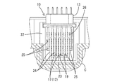
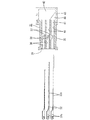
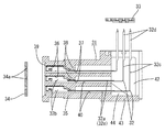
本発明の実施形態1を図1ないし図8によって説明する。この実施形態1では、自動車に搭載されるECU(電子制御ユニット)の基板Kに対して接続される基板用コネクタ10であって、コネクタハウジング11(以下、単にハウジング11という)の周りにECUのケースCが二次成形されるものを例示する。このハウジング11には、ケースC外から相手の雄コネクタ(図示せず)が嵌合可能とされる。なお以下では、ハウジング11における相手の雄コネクタとの嵌合面側を前方とし、その反対側を後方とし、また上下方向については図2などを基準とする。
参考例を図9ないし図12によって説明する。この参考例では、実施形態1の中継端子などを省略したものを示す。
本発明は上記記述及び図面によって説明した実施形態に限定されるものではなく、例えば次のような実施形態も本発明の技術的範囲に含まれ、さらに、下記以外にも要旨を逸脱しない範囲内で種々変更して実施することができる。
(1)上記した実施形態では、端子保持部における端子金具の周りを除肉した変位許容凹部を例示したが、例えば端子金具の周りにその変位を許容する弾性部材を設けることで変位許容領域を構成したものも本発明に含まれる。
(4)上記した実施形態では、相手の雄コネクタと嵌合される基板用コネクタ(嵌合部分が雌型のもの)を示したが、相手の雌コネクタと嵌合される基板用コネクタ(嵌合部分が雄型のもの)にも本発明は適用可能である。
11,31…ハウジング
12,32…端子金具
14,35…端子保持部
15…本体部
16…中継端子ホルダ
17…端子本体
18…中継端子
18a…接続部
23,43…壁部
24,44…補強壁
25,40…変位許容凹部(変位許容領域)
26,41…補強部
C…ケース(二次成形部)
K…基板
M…金型
Claims (2)
- コネクタハウジングには、端子金具を後方へ突出した状態で保持可能な端子保持部が設けられるとともに、前記端子金具における突出部分の端部が基板に対して接続されるものにおいて、
前記端子保持部における端子金具の周りには、端子金具がその軸線方向と交差する二方向へ自由に弾性変形することを許容する変位許容領域が設けられ、この変位許容領域は、端子保持部の強度を保つための補強部を有し、その補強部は前記変位許容領域が各端子金具毎に互いに独立した形態となるよう、略格子状をなしており、
前記コネクタハウジングの周りには、二次成形部が二次成形され、且つ前記二次成形部は、前記端子保持部のうち少なくとも前記補強部の周面を覆う形態とされ、
前記端子保持部は、本体部と、嵌合筒部を有しその嵌合筒部が前記本体部の前面側に嵌合して組み付けられる中継端子用ホルダとから構成されるとともに、前記端子金具は、前記本体部に後方へ突出した状態で装着される端子本体と、前記中継端子ホルダに装着される中継端子とから構成されており、
前記中継端子は、前後に一対の接続部を有しており、このうち後側の接続部が前記中継端子ホルダを前記本体部に組み付けるのに伴って前記端子本体に接続され、前側の接続部が前記コネクタハウジングに対して嵌合される相手コネクタと接続されるようになっていることを特徴とする基板用コネクタ。 - 前記端子保持部には、前記端子金具よりも後方へ延出する壁部が設けられ、この壁部が二次成形時に使用される金型によって保持されるようになっているとともに、前記壁部と前記端子保持部とを連結する補強壁が設けられていることを特徴とする請求項1記載の基板用コネクタ。
Priority Applications (4)
| Application Number | Priority Date | Filing Date | Title |
|---|---|---|---|
| JP2004211855A JP4356548B2 (ja) | 2004-07-20 | 2004-07-20 | 基板用コネクタ |
| DE102005032950A DE102005032950B4 (de) | 2004-07-20 | 2005-07-14 | Verbinder und Verfahren zu seinem Ausbilden |
| US11/185,639 US7278862B2 (en) | 2004-07-20 | 2005-07-19 | Connector |
| CNB2005100860070A CN100463296C (zh) | 2004-07-20 | 2005-07-20 | 连接器及其制造方法 |
Applications Claiming Priority (1)
| Application Number | Priority Date | Filing Date | Title |
|---|---|---|---|
| JP2004211855A JP4356548B2 (ja) | 2004-07-20 | 2004-07-20 | 基板用コネクタ |
Publications (2)
| Publication Number | Publication Date |
|---|---|
| JP2006032218A JP2006032218A (ja) | 2006-02-02 |
| JP4356548B2 true JP4356548B2 (ja) | 2009-11-04 |
Family
ID=35657818
Family Applications (1)
| Application Number | Title | Priority Date | Filing Date |
|---|---|---|---|
| JP2004211855A Expired - Lifetime JP4356548B2 (ja) | 2004-07-20 | 2004-07-20 | 基板用コネクタ |
Country Status (4)
| Country | Link |
|---|---|
| US (1) | US7278862B2 (ja) |
| JP (1) | JP4356548B2 (ja) |
| CN (1) | CN100463296C (ja) |
| DE (1) | DE102005032950B4 (ja) |
Families Citing this family (24)
| Publication number | Priority date | Publication date | Assignee | Title |
|---|---|---|---|---|
| JP4742877B2 (ja) | 2006-01-18 | 2011-08-10 | 住友電装株式会社 | 樹脂成形品の成形構造 |
| FR2899375A1 (fr) * | 2006-04-04 | 2007-10-05 | Peugeot Citroen Automobiles Sa | Embase multivoie pour la protection d'une ligne electrique et de sa liaison en depart de ligne |
| FR2903236B1 (fr) * | 2006-06-30 | 2008-10-03 | Valeo Sys Controle Moteur Sas | Carte electronique pourvue d'un connecteur en deux parties et procede de fabrication d'une telle carte |
| JP4356768B2 (ja) * | 2007-05-18 | 2009-11-04 | 株式会社デンソー | 電子装置及びその成形金型 |
| CN201054405Y (zh) * | 2007-05-22 | 2008-04-30 | 富士康(昆山)电脑接插件有限公司 | 电连接器 |
| US7491096B1 (en) * | 2007-07-31 | 2009-02-17 | Phoenix Contact Development & Manufacturing Inc. | Modular terminal block |
| JP4863954B2 (ja) * | 2007-09-10 | 2012-01-25 | 新電元工業株式会社 | 電子ユニットおよびその製造方法 |
| US7455552B1 (en) * | 2008-02-06 | 2008-11-25 | Delphi Technologies, Inc. | Overmolded electronic assembly with metal seal ring |
| EP2302742B1 (en) * | 2008-06-30 | 2015-09-02 | Fujitsu Limited | Connector, substrate comprising the same, and electronic device |
| JP5590386B2 (ja) * | 2010-06-03 | 2014-09-17 | 住友電装株式会社 | コネクタ及びコネクタの製造方法 |
| JP5397338B2 (ja) * | 2010-07-21 | 2014-01-22 | 住友電装株式会社 | コネクタの製造方法 |
| JP5605156B2 (ja) | 2010-10-18 | 2014-10-15 | 住友電装株式会社 | ケース一体型コネクタ |
| DE102011006195A1 (de) | 2011-03-28 | 2012-10-04 | Robert Bosch Gmbh | Modulare elektrische Steckverbinderanordnung |
| JP2013089387A (ja) | 2011-10-14 | 2013-05-13 | Yazaki Corp | 端子及びコネクタ |
| DE102012001478A1 (de) | 2012-01-26 | 2013-08-01 | Wabco Gmbh | Verfahren zum Herstellen eines Steuergerätgehäuses sowie ein nach diesem Verfahren hergestelltes Steuergerätgehäuse |
| EP2634877B1 (fr) * | 2012-02-28 | 2015-06-03 | Pompes Salmson | Procédé de fabrication d'un boitier de commande pour pompe de circulation |
| JP5525574B2 (ja) * | 2012-08-07 | 2014-06-18 | ホシデン株式会社 | 部品モジュール及び部品モジュールの製造方法 |
| JP5965789B2 (ja) * | 2012-08-31 | 2016-08-10 | 矢崎総業株式会社 | コネクタ |
| DE102013206095B4 (de) * | 2013-04-05 | 2020-10-01 | Lenze Automation Gmbh | Adapter zum Anschließen an Anschlusskontakte eines elektrischen Steuergeräts |
| US10700462B2 (en) | 2018-01-18 | 2020-06-30 | Interplex Industries, Inc. | Connector housing |
| WO2020009925A1 (en) * | 2018-07-01 | 2020-01-09 | Interplex Industries, Inc. | Connector housing and method of manufacturing same |
| JP7081549B2 (ja) * | 2019-03-27 | 2022-06-07 | 株式会社オートネットワーク技術研究所 | コネクタ |
| JP2025055857A (ja) * | 2023-09-27 | 2025-04-08 | 株式会社オートネットワーク技術研究所 | 基板用コネクタ |
| JP2025055845A (ja) * | 2023-09-27 | 2025-04-08 | 株式会社オートネットワーク技術研究所 | 基板用コネクタ |
Family Cites Families (7)
| Publication number | Priority date | Publication date | Assignee | Title |
|---|---|---|---|---|
| US5215471A (en) * | 1989-06-13 | 1993-06-01 | General Datacomm, Inc. | Electrical connectors having tapered spring contact elements for direct mating to holes |
| JP2752024B2 (ja) * | 1992-03-25 | 1998-05-18 | 矢崎総業株式会社 | プリント基板用コネクタ |
| JP3404832B2 (ja) | 1993-10-15 | 2003-05-12 | 住友電装株式会社 | コネクタの製造方法及びコネクタ |
| NL9302227A (nl) * | 1993-12-21 | 1995-07-17 | Connector Systems Tech Nv | Elektrische connector met een de aansluitpennen positionerend lichaam. |
| US5382169A (en) | 1994-01-14 | 1995-01-17 | Labinal Components And Systems, Inc. | Electrical connectors |
| US6256572B1 (en) | 1999-03-30 | 2001-07-03 | Kelsey-Hayes Company | Remote programming of an ABS electronic control module |
| JP3997852B2 (ja) | 2002-06-28 | 2007-10-24 | 住友電装株式会社 | インサート成形コネクタ |
-
2004
- 2004-07-20 JP JP2004211855A patent/JP4356548B2/ja not_active Expired - Lifetime
-
2005
- 2005-07-14 DE DE102005032950A patent/DE102005032950B4/de not_active Expired - Lifetime
- 2005-07-19 US US11/185,639 patent/US7278862B2/en not_active Expired - Lifetime
- 2005-07-20 CN CNB2005100860070A patent/CN100463296C/zh not_active Expired - Lifetime
Also Published As
| Publication number | Publication date |
|---|---|
| US7278862B2 (en) | 2007-10-09 |
| CN1761108A (zh) | 2006-04-19 |
| DE102005032950B4 (de) | 2009-02-05 |
| DE102005032950A1 (de) | 2006-02-23 |
| CN100463296C (zh) | 2009-02-18 |
| JP2006032218A (ja) | 2006-02-02 |
| US20060019516A1 (en) | 2006-01-26 |
Similar Documents
| Publication | Publication Date | Title |
|---|---|---|
| JP4356548B2 (ja) | 基板用コネクタ | |
| CN110582896B (zh) | 基板用连接器 | |
| US12362519B2 (en) | Connector | |
| CN112236905B (zh) | 电路基板装置及基板用连接器 | |
| CN102265464B (zh) | 电连接器 | |
| JP4702205B2 (ja) | コネクタ | |
| JP2010040183A (ja) | コネクタ | |
| JP6244345B2 (ja) | コネクタ | |
| CN112335134A (zh) | 电路基板装置 | |
| JP4470116B2 (ja) | コネクタ付きケースの成形構造 | |
| JP4782024B2 (ja) | 電子接続箱及びその組立方法 | |
| JP2013033633A (ja) | コネクタ | |
| US7819695B2 (en) | Multi-unit connector | |
| JP2024170742A (ja) | コネクタ | |
| JP2010212196A (ja) | 電子機器 | |
| JP4356590B2 (ja) | 基板用コネクタにおける端子金具とアライメントプレートの組付け構造 | |
| JP2014211979A (ja) | 基板用コネクタおよびケース一体型コネクタ | |
| JP6032109B2 (ja) | 基板用コネクタおよびケース一体型コネクタ | |
| JP4385932B2 (ja) | 基板用コネクタ | |
| JP4862612B2 (ja) | コネクタ及びその成形用の金型 | |
| WO2024005061A1 (ja) | コネクタ | |
| JP2024125839A (ja) | 電気接続箱 | |
| WO2024004610A1 (ja) | コネクタ | |
| JP5573267B2 (ja) | コネクタ | |
| JP5494262B2 (ja) | 電気接続箱 |
Legal Events
| Date | Code | Title | Description |
|---|---|---|---|
| RD04 | Notification of resignation of power of attorney |
Free format text: JAPANESE INTERMEDIATE CODE: A7424 Effective date: 20061025 |
|
| A621 | Written request for application examination |
Free format text: JAPANESE INTERMEDIATE CODE: A621 Effective date: 20070115 |
|
| A977 | Report on retrieval |
Free format text: JAPANESE INTERMEDIATE CODE: A971007 Effective date: 20081211 |
|
| A131 | Notification of reasons for refusal |
Free format text: JAPANESE INTERMEDIATE CODE: A131 Effective date: 20081222 |
|
| A521 | Request for written amendment filed |
Free format text: JAPANESE INTERMEDIATE CODE: A523 Effective date: 20090209 |
|
| A131 | Notification of reasons for refusal |
Free format text: JAPANESE INTERMEDIATE CODE: A131 Effective date: 20090407 |
|
| A521 | Request for written amendment filed |
Free format text: JAPANESE INTERMEDIATE CODE: A523 Effective date: 20090608 |
|
| TRDD | Decision of grant or rejection written | ||
| A01 | Written decision to grant a patent or to grant a registration (utility model) |
Free format text: JAPANESE INTERMEDIATE CODE: A01 Effective date: 20090714 |
|
| A01 | Written decision to grant a patent or to grant a registration (utility model) |
Free format text: JAPANESE INTERMEDIATE CODE: A01 |
|
| A61 | First payment of annual fees (during grant procedure) |
Free format text: JAPANESE INTERMEDIATE CODE: A61 Effective date: 20090727 |
|
| FPAY | Renewal fee payment (event date is renewal date of database) |
Free format text: PAYMENT UNTIL: 20120814 Year of fee payment: 3 |
|
| R150 | Certificate of patent or registration of utility model |
Ref document number: 4356548 Country of ref document: JP Free format text: JAPANESE INTERMEDIATE CODE: R150 Free format text: JAPANESE INTERMEDIATE CODE: R150 |
|
| FPAY | Renewal fee payment (event date is renewal date of database) |
Free format text: PAYMENT UNTIL: 20120814 Year of fee payment: 3 |
|
| FPAY | Renewal fee payment (event date is renewal date of database) |
Free format text: PAYMENT UNTIL: 20130814 Year of fee payment: 4 |
|
| EXPY | Cancellation because of completion of term |