JP4360209B2 - 配管支持装置 - Google Patents
配管支持装置 Download PDFInfo
- Publication number
- JP4360209B2 JP4360209B2 JP2004010950A JP2004010950A JP4360209B2 JP 4360209 B2 JP4360209 B2 JP 4360209B2 JP 2004010950 A JP2004010950 A JP 2004010950A JP 2004010950 A JP2004010950 A JP 2004010950A JP 4360209 B2 JP4360209 B2 JP 4360209B2
- Authority
- JP
- Japan
- Prior art keywords
- pipe
- bracket member
- support device
- presser
- members
- Prior art date
- Legal status (The legal status is an assumption and is not a legal conclusion. Google has not performed a legal analysis and makes no representation as to the accuracy of the status listed.)
- Expired - Fee Related
Links
Images




Landscapes
- Supports For Pipes And Cables (AREA)
- Connection Of Plates (AREA)
Description
Claims (2)
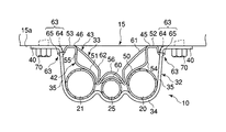
- 複数の管部材を配管支持部に固定するための配管支持装置であって、
両端部が前記配管支持部に固定される第1ブラケット部材と、
前記第1ブラケット部材に取り付けられた第2ブラケット部材とを有し、
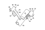
前記第2ブラケット部材は、
前記複数の管部材のうち1本または2本を前記第1ブラケット部材との間で挾持する第1押え部と、
前記第1押え部とは独立して弾性変形できるように形成され、前記第1押え部によって挾持される管部材以外の管部材を前記第1ブラケット部材との間で挾持する第2押え部とを具備し、
前記第2ブラケット部材の一部に、前記配管支持部に向かって突き出る突出部を有し、該突出部は前記第1ブラケット部材の両端部が前記配管支持部に固定された状態において前記配管支持部によって押されることにより前記第1押え部および第2押え部をそれぞれの管部材に向かって押し付ける形状をなしている
ことを特徴とする配管支持装置。 - 前記第1押え部と前記第2押え部のそれぞれの両端が前記第2ブラケット部材の両端部において一体に連なり、かつ、前記突出部が該第2ブラケット部材の両端部に形成されている
ことを特徴とする請求項1に記載の配管支持装置。
Priority Applications (1)
| Application Number | Priority Date | Filing Date | Title |
|---|---|---|---|
| JP2004010950A JP4360209B2 (ja) | 2004-01-19 | 2004-01-19 | 配管支持装置 |
Applications Claiming Priority (1)
| Application Number | Priority Date | Filing Date | Title |
|---|---|---|---|
| JP2004010950A JP4360209B2 (ja) | 2004-01-19 | 2004-01-19 | 配管支持装置 |
Publications (2)
| Publication Number | Publication Date |
|---|---|
| JP2005201419A JP2005201419A (ja) | 2005-07-28 |
| JP4360209B2 true JP4360209B2 (ja) | 2009-11-11 |
Family
ID=34823524
Family Applications (1)
| Application Number | Title | Priority Date | Filing Date |
|---|---|---|---|
| JP2004010950A Expired - Fee Related JP4360209B2 (ja) | 2004-01-19 | 2004-01-19 | 配管支持装置 |
Country Status (1)
| Country | Link |
|---|---|
| JP (1) | JP4360209B2 (ja) |
-
2004
- 2004-01-19 JP JP2004010950A patent/JP4360209B2/ja not_active Expired - Fee Related
Also Published As
| Publication number | Publication date |
|---|---|
| JP2005201419A (ja) | 2005-07-28 |
Similar Documents
| Publication | Publication Date | Title |
|---|---|---|
| JP5309901B2 (ja) | 取付構造 | |
| US10183637B2 (en) | Battery carrier including a base member and a clamp member | |
| JP4941081B2 (ja) | 管状の物体又はホース形状の物体を固定するクランプ | |
| JP6352437B2 (ja) | チューブ、特に自動車のバッテリと接触するように設計された熱交換器のチューブ用の支持装置 | |
| JP6790033B2 (ja) | シール部材を有するプロファイルクランプ | |
| EP2541117B1 (en) | Hose clamp | |
| JP5919659B2 (ja) | 固定金具および太陽電池ユニット | |
| JP4948545B2 (ja) | 金属シートナット | |
| KR20100120366A (ko) | 호스 체결용 클램프의 지지구조체 | |
| CN116685775A (zh) | 夹片和螺母组件 | |
| JP5722104B2 (ja) | 支持装置 | |
| JP4360209B2 (ja) | 配管支持装置 | |
| JP2026012496A (ja) | 配管支持部材 | |
| JP5719063B1 (ja) | Uボルトユニット | |
| JP2008514873A (ja) | ガス発生器カートリッジを固定するためのクランプリング | |
| KR101462626B1 (ko) | 비닐하우스용 파이프 체결장치 | |
| KR200411822Y1 (ko) | 배관 클램프 | |
| JP4279076B2 (ja) | 取付クリップ | |
| JP2011244289A (ja) | 取付金具 | |
| JP4874036B2 (ja) | 変圧器の固定構造およびその取付バンド | |
| KR200441056Y1 (ko) | 온수 분배기의 체결구조 | |
| CN216843440U (zh) | 一种汽车空调管路固定管夹 | |
| US12036925B2 (en) | Housing, in particular for a sensor device | |
| JPH0682487U (ja) | 車体への配管取付構造 | |
| US9243740B2 (en) | Bracket assembly for engine compartment component |
Legal Events
| Date | Code | Title | Description |
|---|---|---|---|
| A621 | Written request for application examination |
Free format text: JAPANESE INTERMEDIATE CODE: A621 Effective date: 20060324 |
|
| A977 | Report on retrieval |
Free format text: JAPANESE INTERMEDIATE CODE: A971007 Effective date: 20090521 |
|
| A131 | Notification of reasons for refusal |
Free format text: JAPANESE INTERMEDIATE CODE: A131 Effective date: 20090526 |
|
| A521 | Request for written amendment filed |
Free format text: JAPANESE INTERMEDIATE CODE: A523 Effective date: 20090625 |
|
| TRDD | Decision of grant or rejection written | ||
| A01 | Written decision to grant a patent or to grant a registration (utility model) |
Free format text: JAPANESE INTERMEDIATE CODE: A01 Effective date: 20090721 |
|
| A01 | Written decision to grant a patent or to grant a registration (utility model) |
Free format text: JAPANESE INTERMEDIATE CODE: A01 |
|
| A61 | First payment of annual fees (during grant procedure) |
Free format text: JAPANESE INTERMEDIATE CODE: A61 Effective date: 20090803 |
|
| R150 | Certificate of patent or registration of utility model |
Free format text: JAPANESE INTERMEDIATE CODE: R150 Ref document number: 4360209 Country of ref document: JP Free format text: JAPANESE INTERMEDIATE CODE: R150 |
|
| FPAY | Renewal fee payment (event date is renewal date of database) |
Free format text: PAYMENT UNTIL: 20120821 Year of fee payment: 3 |
|
| FPAY | Renewal fee payment (event date is renewal date of database) |
Free format text: PAYMENT UNTIL: 20130821 Year of fee payment: 4 |
|
| FPAY | Renewal fee payment (event date is renewal date of database) |
Free format text: PAYMENT UNTIL: 20130821 Year of fee payment: 4 |
|
| FPAY | Renewal fee payment (event date is renewal date of database) |
Free format text: PAYMENT UNTIL: 20140821 Year of fee payment: 5 |
|
| S531 | Written request for registration of change of domicile |
Free format text: JAPANESE INTERMEDIATE CODE: R313531 |
|
| R350 | Written notification of registration of transfer |
Free format text: JAPANESE INTERMEDIATE CODE: R350 |
|
| LAPS | Cancellation because of no payment of annual fees |