JP4367706B2 - Wireless transmission method, wireless transmitter, and wireless LAN system - Google Patents
Wireless transmission method, wireless transmitter, and wireless LAN system Download PDFInfo
- Publication number
- JP4367706B2 JP4367706B2 JP2004320374A JP2004320374A JP4367706B2 JP 4367706 B2 JP4367706 B2 JP 4367706B2 JP 2004320374 A JP2004320374 A JP 2004320374A JP 2004320374 A JP2004320374 A JP 2004320374A JP 4367706 B2 JP4367706 B2 JP 4367706B2
- Authority
- JP
- Japan
- Prior art keywords
- data
- wireless
- unit
- data units
- determined
- Prior art date
- Legal status (The legal status is an assumption and is not a legal conclusion. Google has not performed a legal analysis and makes no representation as to the accuracy of the status listed.)
- Expired - Fee Related
Links
Images







Landscapes
- Data Exchanges In Wide-Area Networks (AREA)
- Small-Scale Networks (AREA)
- Mobile Radio Communication Systems (AREA)
Description
本発明は、無線パケットを用いて無線送信を行なう無線送信機に関する。 The present invention relates to a wireless transmitter that performs wireless transmission using a wireless packet.
近年、無線LANにおいて100Mbit/sクラスの高速化が求められている。無線LANの高速化の達成方法の一つとしては、送受信機において複数のアンテナを使用するMIMO方式を用いた方法が有望である。 In recent years, a high speed of 100 Mbit / s class is required in a wireless LAN. As a method for achieving high-speed wireless LAN, a method using a MIMO scheme using a plurality of antennas in a transceiver is promising.
このMIMO方式を用いた場合、図31に示すように、DATA部の伝送速度は向上する一方、1つの無線パケットあたり一定の情報量を伝送する場合には、プリアンブル部が送信アンテナ数に応じて長くなり、かつDATA部は伝送速度が向上する分短くなるため、時間的に見てデータ送信に使う割合が少なくなる。すなわち、データの伝送効率が悪くなるという問題がある。このように、MIMO方式を用いた場合に、プリアンブル部が送信アンテナ数に応じて長くなることは、特開2002−374224、や特開2003−060604にも記載されている。 When this MIMO scheme is used, as shown in FIG. 31, the transmission speed of the DATA section is improved, but when a certain amount of information is transmitted per one wireless packet, the preamble section depends on the number of transmitting antennas. Since the length becomes longer and the DATA portion becomes shorter as the transmission speed is improved, the ratio used for data transmission decreases with time. That is, there is a problem that the data transmission efficiency deteriorates. As described above, in the case of using the MIMO scheme, the fact that the preamble portion becomes longer according to the number of transmission antennas is also described in JP-A Nos. 2002-374224 and 2003-060604.
そこで、上記MIMO方式を適用した無線LANにおいては、図32に示すように、1つの無線パケットで複数のPSDUを連結し送信することによりデータの伝送効率を上げる方法が検討されている。また、上記の例と同じように、複数のMSDU(MAC Service Data Unit)を連結し、1つのMPDU(MAC Protocol Data Unit)として送信を行なう方法が、特開2003−324445でも提案されている。 Therefore, in a wireless LAN to which the MIMO scheme is applied, as shown in FIG. 32, a method for increasing data transmission efficiency by concatenating and transmitting a plurality of PSDUs with one wireless packet is being studied. Similarly to the above example, Japanese Patent Laid-Open No. 2003-324445 also proposes a method of concatenating a plurality of MSDUs (MAC Service Data Units) and performing transmission as one MPDU (MAC Protocol Data Unit).
ここで、図33に示すように、「PSDU」および「MSDU」については、IEEE802.11aの仕様書であるIEEE Std 802.11a−1999記載の通り、MACに入力されるデータの単位をMSDUと呼び、これを暗号化した後MAC Header、CRC(Cyclic Redundancy Check、またはFCS(Frame Check Sequence))を付加したものをMPDUと呼び、これをPHYに出力したものをPSDUと呼ぶ。このPSDUに対しスクランブル、誤り訂正符号の処理を行ない、復調時に必要となるプリアンブル、signal field(変調方式などの情報を含む)を付加し、変調を行ない、無線媒体に送信可能な形にした後(以下、これを「無線パケット」と呼称する。)、信号の送信を行なうものとする。なお、このような無線パケットを構成するそれぞれのデータのまとまりを、データユニットと呼称する。 Here, as shown in FIG. 33, for “PSDU” and “MSDU”, as described in IEEE Std 802.11a-1999, which is the IEEE 802.11a specification, the unit of data input to the MAC is MSDU. Called, encrypted, and then added with a MAC header and CRC (Cyclic Redundancy Check, or FCS (Frame Check Sequence)) are called MPDUs, and those output to PHY are called PSDUs. After scrambling and error correction code processing for this PSDU, adding a preamble and signal fields (including information such as modulation scheme) necessary for demodulation, modulating, and making it possible to transmit to a wireless medium (Hereinafter, this is referred to as a “wireless packet”.) Signal transmission shall be performed. A group of data constituting such a wireless packet is referred to as a data unit.
また、無線LANの規格の一つであるIEEE802.11eにおける「MAC」の構成は、以下の通りである。図34に示すように、MAC310への入力データは、buffer311に蓄積され、buffer311からはscheduler312の指示により適切なタイミングで適切なAC(Access Category)に属するデータが出力される。この出力データは、暗号化部313により暗号化処理をされた後、MACHeader付加部314によりMAC Headerが付加され、FCS付加部315によってFrame Check Sequenceが付加された後、PHYにデータが出力される。controller316は、制御信号の処理や各ブロックの制御を行なう。また、scheduler312は、タイマに従い、各ブロックの制御を行なう。
The configuration of “MAC” in IEEE 802.11e, which is one of the wireless LAN standards, is as follows. As shown in FIG. 34, input data to the
また、上記buffer311は図35に示すように構成されている。buffer311に入力されたDATAは、Access Category毎にマッピング処理を行なうMCA部311aにより、AC毎に用意されたキュー311b〜311eに蓄積される。図34に示すscheduler312から送信可能を示す信号が入力された場合は、これら各キューに蓄積されたデータが各CSMA/CA311f〜311iにおける動作により競争を行った後、Internal Collision Resolution311kにより複数キューの送信タイミングが重なった場合には、優先度の高いほうを送信する。なお上記動作の詳細は、IEEE P802.11e/D6.0 November 2003に記載されている通りである。また上記キュー311b〜311eに蓄積されたデータは、ACKにより受信成功が確認された後、消去されるものとする。なお、ここで述べるACとは、Best Effort,Video Probe,Video, VoiceなどQoSのクラスを示すものである。
The
次に、上記buffer311の動作について図36に示すフローチャートを用いて説明する。先ず、buffer311にデータが入力されると(ステップF1)、この入力されたデータをAC毎に用意されたキューに振り分ける(ステップF2)。次に、ACKにより、受信成功が確認された送信データをキューから削除し(ステップF3)、スケジューラから送信可能信号を受信したかどうかを判断する(ステップF4)。スケジューラから送信可能信号を受信していない場合は、ステップF1へ移行し、スケジューラから送信可能信号を受信した場合は、キュー毎にCSMA/CAの動作を行ない、送信データを選択する(ステップF5)。この後、ステップF5において選択されたデータを送信し(ステップF6)、ステップF1へ移行する。
しかしながら、従来の技術のように複数のMSDUを連結した場合には、パケットを無線媒体に送信するまでに多くのMSDUをバッファに蓄えておく必要があるため、図37に示すように、伝送遅延が大きくなる欠点がある。すなわち、図37に示すように、MSDUが1個である場合は、MSDUをバッファに蓄積する必要がないため、処理遅延が少ないのに対し、MSDUを複数連結させる場合は、多くのMSDUをバッファに蓄積させる必要があるため、処理遅延が大きくなってしまう。特に、ストリーミングなど伝送遅延が、伝送品質に大きな影響を与えるものに関しては、伝送遅延を極力小さくする必要がある。伝送遅延を小さくするには、QoS(Quality of Service)を考慮したMSDUの連結数の決定が不可欠となる。 However, when a plurality of MSDUs are concatenated as in the prior art, it is necessary to store many MSDUs in a buffer before the packet is transmitted to the wireless medium. Therefore, as shown in FIG. Has the disadvantage of becoming larger. That is, as shown in FIG. 37, when there is one MSDU, there is no need to store the MSDU in the buffer, so the processing delay is small, but when multiple MSDUs are connected, many MSDUs are buffered. Therefore, the processing delay becomes large. In particular, for transmission such as streaming that greatly affects transmission quality, it is necessary to minimize the transmission delay. In order to reduce the transmission delay, it is indispensable to determine the number of connected MSDUs in consideration of QoS (Quality of Service).
本発明は、このような事情に鑑みてなされたものであり、QoSを考慮してMSDUの連結数を決定することにより、伝送の効率化を図ることができる無線送信方法、無線送信機および無線LANシステムを提供することを目的とする。 The present invention has been made in view of such circumstances, and a wireless transmission method, a wireless transmitter, and a wireless transmitter capable of improving transmission efficiency by determining the number of MSDU connections in consideration of QoS. An object is to provide a LAN system.
(1)上記の目的を達成するため、本発明は、以下のような手段を講じた。すなわち、本発明に係る無線送信方法は、通信相手先の無線通信機およびQoSクラスに対応して割り当てられた複数のキューと、前記各キューに蓄積されたデータユニット数が、一つの無線パケットに含まれるデータユニット数として定められた閾値(yi)を超えたかどうか判定し、いずれかの前記キューにおいて蓄積されたデータユニットが前記閾値を超えた場合、前記蓄積されたデータユニットを出力することを特徴としている。 (1) In order to achieve the above object, the present invention has taken the following measures. That is, in the wireless transmission method according to the present invention, a plurality of queues assigned corresponding to a communication partner's wireless communication device and QoS class, and the number of data units accumulated in each of the queues are combined into one wireless packet. It is determined whether or not a threshold value (yi) defined as the number of included data units has been exceeded, and if the accumulated data units in any of the queues exceed the threshold value, the accumulated data units are output. It is a feature.
このように、通信相手先の無線通信機およびQoSクラスに対応して割当てられた複数のキューに蓄積されたデータユニット数が、一つの無線パケットに含まれるデータユニット数として定められた閾値を超えた場合に、蓄積されたデータユニットを出力するので、一つの無線パケットに通信相手先の無線通信機およびQoSクラス毎に蓄積された複数のデータユニットを含めることができる。これにより、通信相手先の無線通信機およびQoSクラス毎にデータユニットを効率的に連結させることが可能となる。 As described above, the number of data units accumulated in a plurality of queues assigned in correspondence with the wireless communication device of the communication partner and the QoS class exceeds the threshold set as the number of data units included in one wireless packet. In this case, since the accumulated data unit is output, it is possible to include a plurality of data units accumulated for each communication partner wireless communication device and QoS class in one wireless packet. As a result, it is possible to efficiently connect the data units for each wireless communication device and QoS class of the communication partner.
(2)また、本発明に係る無線送信方法は、入力された各データユニットの長さを示すデータユニット長情報に基づいて、前記データユニット毎に誤り訂正符号化を行い、前記誤り訂正符号化後の各データユニットを連結させることを特徴としている。 (2) Further, the wireless transmission method according to the present invention performs error correction coding for each data unit based on data unit length information indicating the length of each input data unit, and the error correction coding. It is characterized by connecting each subsequent data unit.
この構成により、複数のデータユニットを連結させて一つの無線パケットを効率的に生成することができる。また、データユニット毎に誤り訂正符号化を行なうので、データパケット毎に誤り訂正符号を終端させることができ、データパケットの間での誤りの伝搬を生じにくくさせることが可能となる。 With this configuration, it is possible to efficiently generate one wireless packet by connecting a plurality of data units. Further, since error correction encoding is performed for each data unit, the error correction code can be terminated for each data packet, and it is possible to make it difficult for error propagation to occur between data packets.
(3)また、本発明に係る無線送信方法は、QoSクラスの異なるアプリケーション毎に定められるQoSパラメータに基づいて、一つの無線パケットに含まれるデータユニット数として定められた閾値(yi)を決定することを特徴としている。 (3) In addition, the wireless transmission method according to the present invention determines a threshold value (yi) defined as the number of data units included in one wireless packet based on QoS parameters defined for each application of different QoS classes. It is characterized by that.
このように、QoSを考慮して閾値を決定するので、一つの無線パケットに含まれるデータユニット数をQoSに応じて決めることができ、伝送効率の向上または伝送遅延の解消を図ることが可能となる。 Thus, since the threshold value is determined in consideration of QoS, the number of data units included in one wireless packet can be determined according to QoS, and it is possible to improve transmission efficiency or eliminate transmission delay. Become.
(4)また、本発明に係る無線送信方法は、QoSクラスの異なるアプリケーション毎に定められるQoSパラメータと、QoSクラスの異なるアプリケーションおよび通信相手先の無線通信機毎の待機中の再送データユニットの再送回数とに基づいて、一つの無線パケットに含まれるデータユニット数として定められた閾値(yi)を決定することを特徴としている。 (4) In addition, the wireless transmission method according to the present invention includes a QoS parameter defined for each application having a different QoS class, and retransmission of a retransmission data unit in standby for each application having a different QoS class and a wireless communication device of a communication partner. A threshold (yi) determined as the number of data units included in one wireless packet is determined based on the number of times.
このように、QoSパラメータのみならず、送信待機中の再送データユニットの再送回数を考慮して、閾値を決定するので、伝送遅延を小さくすることが可能となる。 In this way, since the threshold value is determined in consideration of not only the QoS parameter but also the number of retransmissions of the retransmission data unit waiting for transmission, the transmission delay can be reduced.
(5)また、本発明に係る無線送信方法は、QoSクラスの異なるアプリケーション毎に定められるQoSパラメータに基づいて、一つの無線パケットに含まれるデータユニット数として定められた閾値(yi)を決定し、この閾値(yi)に、前記QoSクラスの異なるアプリケーションおよび通信相手先の無線通信機毎の待機中の再送データユニットの数(pi)を加算して得られた数値を、一つの無線パケットに含まれるデータユニット数とすることを特徴としている。 (5) In the wireless transmission method according to the present invention, a threshold (yi) determined as the number of data units included in one wireless packet is determined based on a QoS parameter defined for each application having a different QoS class. The numerical value obtained by adding the number of waiting retransmission data units (pi) for each application and the communication partner wireless communication device with different QoS classes to the threshold value (yi) is obtained as one wireless packet. It is characterized by the number of data units included.
このように、上記のように定められるQoSパラメータから閾値を決定し、この閾値に、QoSクラスの異なるアプリケーションおよび通信相手先の無線通信機毎の待機中の再送データユニットの数を加算して得られた数値を、一つの無線パケットに含まれるデータユニット数とするので、伝送効率を向上させると共に、伝送遅延を小さくすることが可能となる。 Thus, a threshold value is determined from the QoS parameters determined as described above, and the threshold value is obtained by adding the number of waiting retransmission data units for each application and communication partner wireless communication device having a different QoS class. Since the obtained numerical value is the number of data units included in one wireless packet, it is possible to improve transmission efficiency and reduce transmission delay.
(6)また、本発明に係る無線送信方法は、QoSクラスの異なるアプリケーション毎に定められるQoSパラメータに基づいて、一つの無線パケットに含まれるデータユニット数として定められた閾値(yi)を決定し、前記QoSクラスの異なるアプリケーションおよび通信相手先の無線通信機毎の待機中の再送データユニットの最大の再送回数(mi)が0である場合は、一つの無線パケットに含まれるデータユニット数を、前記決定した閾値とする一方、前記QoSクラスの異なるアプリケーションおよび通信相手先の無線通信機毎の待機中の再送データユニットの最大の再送回数(mi)が0でない場合は、前記閾値を0とすることを特徴としている。 (6) In the wireless transmission method according to the present invention, a threshold (yi) determined as the number of data units included in one wireless packet is determined based on a QoS parameter defined for each application having a different QoS class. When the maximum number of retransmissions (mi) of waiting retransmission data units for each application and communication partner wireless communication device with different QoS classes is 0, the number of data units included in one wireless packet is While the determined threshold value is set, the threshold value is set to 0 when the maximum number of retransmissions (mi) of the waiting retransmission data unit for each application and communication partner wireless communication device with different QoS classes is not 0. It is characterized by that.
このように、QoSクラスの異なるアプリケーションおよび通信相手先の無線通信機毎の待機中の再送データユニットの最大の再送回数が0でない場合、すなわち、再送すべきデータユニットが存在している場合は、閾値を0として、一つの無線パケットに再送データユニットのみを含ませるので、伝送遅延を小さくすることが可能となる。 In this way, when the maximum number of retransmissions of waiting retransmission data units for each application and communication partner wireless communication device with different QoS classes is not 0, that is, when there are data units to be retransmitted, Since the threshold value is set to 0 and only one retransmission data unit is included in one wireless packet, the transmission delay can be reduced.
(7)また、本発明に係る無線送信方法は、前記データユニットの最大の再送回数が大きいほど、前記閾値を小さくし、前記データユニットの最大の再送回数が小さいほど、前記閾値を大きくすることを特徴としている。 (7) In the wireless transmission method according to the present invention, the threshold is decreased as the maximum number of retransmissions of the data unit is increased, and the threshold is increased as the maximum number of retransmissions of the data unit is decreased. It is characterized by.
このように、データユニットの最大の再送回数が大きく、伝送遅延が問題となる場合は、伝送効率よりも伝送遅延の解消を優先させ、閾値を小さくすることによって、伝送遅延を解消させることができる。一方、データユニットの最大の再送回数が小さく、伝送遅延が問題とならない場合は、閾値を大きくすることによって、伝送効率を向上させることが可能となる。 In this way, when the maximum number of retransmissions of the data unit is large and transmission delay becomes a problem, it is possible to eliminate the transmission delay by prioritizing the cancellation of the transmission delay over the transmission efficiency and reducing the threshold. . On the other hand, when the maximum number of retransmissions of the data unit is small and transmission delay is not a problem, it is possible to improve transmission efficiency by increasing the threshold value.
(8)また、本発明に係る無線送信方法は、前記QoSパラメータは、許容遅延時間、前記MAC部に入力されるデータの平均データ速度、およびMAC部に入力されるデータサイズの平均値であって、アプリケーションが許容可能なものであることを特徴としている。 (8) In the wireless transmission method according to the present invention, the QoS parameter includes an allowable delay time, an average data rate of data input to the MAC unit, and an average value of data size input to the MAC unit. The feature is that the application is acceptable.
このように、許容遅延時間、前記MAC部に入力されるデータの平均データ速度、および前記MAC部に入力されるデータサイズの平均値に応じて、閾値を決定することができるので、伝送効率の向上または伝送遅延の解消を図ることが可能となる。 Thus, the threshold can be determined according to the allowable delay time, the average data rate of the data input to the MAC unit, and the average value of the data size input to the MAC unit. It is possible to improve or eliminate transmission delay.
(9)また、本発明に係る無線送信機は、伝送制御を行なうMAC部と、前記MAC部から出力されるデータを通信回線に送出するための電気的な変換および機械的な作業を行なうPHY部と、前記PHY部から出力されるデータを無線信号に変換して送信アンテナから送信する無線送信部と、を備え、複数のデータユニットを含む無線パケットを用いて無線送信を行なう無線送信機であって、通信相手先の無線通信機およびQoSクラスに対応して割当てられた複数のキューと、前記各キューに蓄積されたデータユニット数が、一つの無線パケットに含まれるデータユニット数として定められた閾値(yi)を超えたかどうかを判定する判定部と、前記判定の結果、いずれかの前記キューにおいて蓄積されたデータユニット数が前記閾値(yi)を超えた場合、そのキューに対して蓄積したデータユニットを出力するよう制御する出力制御部と、を備えることを特徴としている。 (9) A wireless transmitter according to the present invention includes a MAC unit that performs transmission control, and an electrical conversion and mechanical operation for sending data output from the MAC unit to a communication line. A wireless transmitter that performs wireless transmission using a wireless packet including a plurality of data units, and a wireless transmission unit that converts data output from the PHY unit into a wireless signal and transmits the wireless signal from a transmission antenna Thus, a plurality of queues assigned corresponding to the wireless communication device of the communication partner and the QoS class, and the number of data units stored in each queue are determined as the number of data units included in one wireless packet. A determination unit that determines whether or not the threshold value (yi) has been exceeded, and as a result of the determination, the number of data units accumulated in any one of the queues exceeds the threshold value (yi) If, it is characterized in that it comprises an output control unit which controls to output data units accumulated for that queue, the.
このように、通信相手先の無線通信機およびQoSクラスに対応して割当てられた複数のキューに蓄積されたデータユニット数が、一つの無線パケットに含まれるデータユニット数として定められた閾値を超えた場合に、蓄積されたデータユニットを出力するので、一つの無線パケットに通信相手先の無線通信機およびQoSクラス毎に蓄積された複数のデータユニットを含めることができる。これにより、通信相手先の無線通信機およびQoSクラス毎にデータユニットを効率的に連結させることが可能となる。 As described above, the number of data units accumulated in a plurality of queues assigned in correspondence with the wireless communication device of the communication partner and the QoS class exceeds the threshold set as the number of data units included in one wireless packet. In this case, since the accumulated data unit is output, it is possible to include a plurality of data units accumulated for each communication partner wireless communication device and QoS class in one wireless packet. As a result, it is possible to efficiently connect the data units for each wireless communication device and QoS class of the communication partner.
(10)また、本発明に係る無線送信機は、伝送制御を行なうMAC部と、前記MAC部から出力されるデータを通信回線に送出するための電気的な変換および機械的な作業を行なうPHY部と、前記PHY部から出力されるデータを無線信号に変換して送信アンテナから送信する無線送信部と、を備え、複数のデータユニットを含む無線パケットを用いて無線送信を行なう無線送信機であって、入力された各データユニットの長さを示すデータユニット長情報に基づいて、前記データユニット毎に誤り訂正符号時の終端処理を行なう終端処理部を備えることを特徴としている。 (10) In addition, a wireless transmitter according to the present invention includes a MAC unit that performs transmission control, and electrical conversion and mechanical work for sending data output from the MAC unit to a communication line. A wireless transmitter that performs wireless transmission using a wireless packet including a plurality of data units, and a wireless transmission unit that converts data output from the PHY unit into a wireless signal and transmits the wireless signal from a transmission antenna A termination processing unit that performs termination processing at the time of error correction coding is provided for each data unit based on the input data unit length information indicating the length of each data unit.
このように、データユニット毎に誤り訂正符号時の終端処理を行なうので、複数のデータユニットを連結させて一つの無線パケットを効率的に生成することができる。これにより、データパケットの間での誤りの伝搬を生じにくくさせることが可能となる。 Thus, since termination processing at the time of error correction code is performed for each data unit, a plurality of data units can be connected to efficiently generate one wireless packet. Thereby, it is possible to make it difficult for error propagation to occur between data packets.
(11)また、本発明に係る無線送信機は、伝送制御を行なうMAC部と、前記MAC部から出力されるデータを通信回線に送出するための電気的な変換および機械的な作業を行なうPHY部と、前記PHY部から出力されるデータを無線信号に変換して送信アンテナから送信する無線送信部と、を備え、複数のデータユニットを含む無線パケットを用いて無線送信を行なう無線送信機であって、QoSクラスの異なるアプリケーション毎に定められるQoSパラメータに基づいて、一つの無線パケットに含まれるデータユニット数として定められた閾値(yi)を決定するMAC制御部を備えることを特徴としている。 (11) A wireless transmitter according to the present invention includes a MAC unit that performs transmission control, and electrical conversion and mechanical work for sending data output from the MAC unit to a communication line. A wireless transmitter that performs wireless transmission using a wireless packet including a plurality of data units, and a wireless transmission unit that converts data output from the PHY unit into a wireless signal and transmits the wireless signal from a transmission antenna A MAC control unit that determines a threshold value (yi) defined as the number of data units included in one wireless packet based on a QoS parameter defined for each application having a different QoS class is provided.
このように、QoSを考慮して閾値を決定するので、一つの無線パケットに含まれるデータユニット数をQoSに応じて決めることができ、伝送効率の向上または伝送遅延の解消を図ることが可能となる。 Thus, since the threshold value is determined in consideration of QoS, the number of data units included in one wireless packet can be determined according to QoS, and it is possible to improve transmission efficiency or eliminate transmission delay. Become.
(12)また、本発明に係る無線送信機は、伝送制御を行なうMAC部と、前記MAC部から出力されるデータを通信回線に送出するための電気的な変換および機械的な作業を行なうPHY部と、前記PHY部から出力されるデータを無線信号に変換して送信アンテナから送信する無線送信部と、を備え、複数のデータユニットを含む無線パケットを用いて無線送信を行なう無線送信機であって、QoSクラスの異なるアプリケーション毎に定められるQoSパラメータと、QoSクラスの異なるアプリケーションおよび通信相手先の無線通信機毎の待機中の再送データユニットの再送回数とに基づいて、一つの無線パケットに含まれるデータユニット数として定められた閾値(yi)を決定するMAC制御部を備えることを特徴としている。 (12) A wireless transmitter according to the present invention includes a MAC unit that performs transmission control, and an electrical conversion and mechanical operation for sending data output from the MAC unit to a communication line. A wireless transmitter that performs wireless transmission using a wireless packet including a plurality of data units, and a wireless transmission unit that converts data output from the PHY unit into a wireless signal and transmits the wireless signal from a transmission antenna Based on the QoS parameters determined for each application of different QoS classes, and the number of retransmissions of the waiting retransmission data unit for each wireless communication device of the communication partner and the different QoS class, It is characterized by including a MAC control unit for determining a threshold value (yi) defined as the number of data units included.
このように、QoSパラメータのみならず、送信待機中の再送データユニットの再送回数を考慮して、閾値を決定するので、伝送遅延を小さくすることが可能となる。 In this way, since the threshold value is determined in consideration of not only the QoS parameter but also the number of retransmissions of the retransmission data unit waiting for transmission, the transmission delay can be reduced.
(13)また、本発明に係る無線送信機において、前記MAC制御部は、QoSクラスの異なるアプリケーション毎に定められるQoSパラメータに基づいて、一つの無線パケットに含まれるデータユニット数として定められた閾値(yi)を決定し、この閾値(yi)に、前記QoSクラスの異なるアプリケーションおよび通信相手先の無線通信機毎の待機中の再送データユニットの数(pi)を加算して得られた数値を、一つの無線パケットに含まれるデータユニット数とすることを特徴としている。 (13) In the wireless transmitter according to the present invention, the MAC control unit may determine a threshold value defined as the number of data units included in one wireless packet based on a QoS parameter defined for each application having a different QoS class. (yi) is determined, and a numerical value obtained by adding the number (pi) of retransmission data units in standby for each of the wireless communication devices of different applications and communication counterparts to the threshold (yi) , The number of data units included in one wireless packet.
このように、上記のように定められるQoSパラメータから閾値を決定し、この閾値に、QoSクラスの異なるアプリケーションおよび通信相手先の無線通信機毎の待機中の再送データユニットの数を加算して得られた数値を、一つの無線パケットに含まれるデータユニット数とするので、伝送効率を向上させると共に、伝送遅延を小さくすることが可能となる。 Thus, a threshold value is determined from the QoS parameters determined as described above, and the threshold value is obtained by adding the number of waiting retransmission data units for each application and communication partner wireless communication device having a different QoS class. Since the obtained numerical value is the number of data units included in one wireless packet, it is possible to improve transmission efficiency and reduce transmission delay.
(14)また、本発明に係る無線送信機において、前記MAC制御部は、QoSクラスの異なるアプリケーション毎に定められるQoSパラメータに基づいて、一つの無線パケットに含まれるデータユニット数として定められた閾値(yi)を決定し、前記QoSクラスの異なるアプリケーションおよび通信相手先の無線通信機毎の待機中の再送データユニットの最大の再送回数(mi)が0である場合は、一つの無線パケットに含まれるデータユニット数を、前記決定した閾値とする一方、前記QoSクラスの異なるアプリケーションおよび通信相手先の無線通信機毎の待機中の再送データユニットの最大の再送回数(mi)が0でない場合は、前記閾値を0とすることを特徴としている。 (14) In the wireless transmitter according to the present invention, the MAC control unit may determine a threshold value defined as the number of data units included in one wireless packet based on a QoS parameter defined for each application having a different QoS class. (yi) is determined and included in one wireless packet when the maximum number of retransmissions (mi) of the waiting retransmission data unit for each application and communication partner wireless communication device with different QoS classes is 0 If the maximum number of retransmissions (mi) of waiting retransmission data units for each application and communication partner wireless communication device is not 0, while the number of data units to be determined is the determined threshold value, The threshold value is set to 0.
このように、QoSクラスの異なるアプリケーションおよび通信相手先の無線通信機毎の待機中の再送データユニットの最大の再送回数が0でない場合、すなわち、再送すべきデータユニットが存在している場合は、閾値を0として、一つの無線パケットに再送データユニットのみを含ませるので、伝送遅延を小さくすることが可能となる。 In this way, when the maximum number of retransmissions of waiting retransmission data units for each application and communication partner wireless communication device with different QoS classes is not 0, that is, when there are data units to be retransmitted, Since the threshold value is set to 0 and only one retransmission data unit is included in one wireless packet, the transmission delay can be reduced.
(15)また、本発明に係る無線送信機において、前記MAC制御部は、前記データユニットの最大の再送回数が大きいほど、前記閾値を小さくし、前記データユニットの最大の再送回数が小さいほど、前記閾値を大きくすることを特徴としている。 (15) In the wireless transmitter according to the present invention, the MAC control unit decreases the threshold as the maximum number of retransmissions of the data unit increases, and decreases the maximum number of retransmissions of the data unit. The threshold value is increased.
このように、データユニットの最大の再送回数が大きく、伝送遅延が問題となる場合は、伝送効率よりも伝送遅延の解消を優先させ、閾値を小さくすることによって、伝送遅延を解消させることができる。一方、データユニットの最大の再送回数が小さく、伝送遅延が問題とならない場合は、閾値を大きくすることによって、伝送効率を向上させることが可能となる。 In this way, when the maximum number of retransmissions of the data unit is large and transmission delay becomes a problem, it is possible to eliminate the transmission delay by prioritizing the cancellation of the transmission delay over the transmission efficiency and reducing the threshold. . On the other hand, when the maximum number of retransmissions of the data unit is small and transmission delay is not a problem, it is possible to improve transmission efficiency by increasing the threshold value.
(16)また、本発明に係る無線送信機において、前記QoSパラメータは、許容遅延時間、前記MAC部に入力されるデータの平均データ速度、および前記MAC部に入力されるデータサイズの平均値であって、アプリケーションが許容可能なものであることを特徴としている。 (16) In the wireless transmitter according to the present invention, the QoS parameter includes an allowable delay time, an average data rate of data input to the MAC unit, and an average value of the data size input to the MAC unit. It is characterized in that the application is acceptable.
このように、許容遅延時間、前記MAC部に入力されるデータの平均データ速度、および前記MAC部に入力されるデータサイズの平均値に応じて、閾値を決定することができるので、伝送効率の向上または伝送遅延の解消を図ることが可能となる。 Thus, the threshold can be determined according to the allowable delay time, the average data rate of the data input to the MAC unit, and the average value of the data size input to the MAC unit. It is possible to improve or eliminate transmission delay.
(17)また、本発明に係るアクセスポイントは、上記いずれかに記載の無線送信機を備えることを特徴としている。 (17) Further, an access point according to the present invention includes any one of the wireless transmitters described above.
このアクセスポイントによれば、通信相手先の無線通信機およびQoSクラスに対応して割当てられた複数のキューに蓄積されたデータユニット数が、一つの無線パケットに含まれるデータユニット数として定められた閾値を超えた場合に、蓄積されたデータユニットを出力するので、一つの無線パケットに通信相手先の無線通信機およびQoSクラス毎に蓄積された複数のデータユニットを含めることができる。これにより、通信相手先の無線通信機およびQoSクラス毎にデータユニットを効率的に連結させることが可能となる。また、QoSを考慮して閾値を決定するので、一つの無線パケットに含まれるデータユニット数をQoSに応じて決めることができ、伝送効率の向上または伝送遅延の解消を図ることが可能となる。 According to this access point, the number of data units stored in a plurality of queues assigned in correspondence with the wireless communication device of the communication partner and the QoS class is determined as the number of data units included in one wireless packet. Since the accumulated data unit is output when the threshold value is exceeded, it is possible to include a plurality of data units accumulated for each communication partner wireless communication device and QoS class in one wireless packet. As a result, it is possible to efficiently connect the data units for each wireless communication device and QoS class of the communication partner. In addition, since the threshold value is determined in consideration of QoS, the number of data units included in one wireless packet can be determined according to QoS, and it is possible to improve transmission efficiency or eliminate transmission delay.
(18)また、本発明に係るステーションは、上記いずれかに記載の無線送信機を備えることを特徴としている。 (18) A station according to the present invention includes any one of the wireless transmitters described above.
このステーションによれば、通信相手先の無線通信機およびQoSクラスに対応して割当てられた複数のキューに蓄積されたデータユニット数が、一つの無線パケットに含まれるデータユニット数として定められた閾値を超えた場合に、蓄積されたデータユニットを出力するので、一つの無線パケットに通信相手先の無線通信機およびQoSクラス毎に蓄積された複数のデータユニットを含めることができる。これにより、通信相手先の無線通信機およびQoSクラス毎にデータユニットを効率的に連結させることが可能となる。また、QoSを考慮して閾値を決定するので、一つの無線パケットに含まれるデータユニット数をQoSに応じて決めることができ、伝送効率の向上または伝送遅延の解消を図ることが可能となる。 According to this station, the number of data units stored in a plurality of queues assigned to correspond to the wireless communication device of the communication partner and the QoS class is a threshold defined as the number of data units included in one wireless packet. Since the accumulated data unit is output when the number exceeds, it is possible to include a plurality of data units accumulated for each communication partner wireless communication device and QoS class in one wireless packet. As a result, it is possible to efficiently connect the data units for each wireless communication device and QoS class of the communication partner. In addition, since the threshold value is determined in consideration of QoS, the number of data units included in one wireless packet can be determined according to QoS, and it is possible to improve transmission efficiency or eliminate transmission delay.
(19)また、本発明に係る無線LANシステムは、上記のアクセスポイントと、上記のステーションと、から構成されることを特徴としている。 (19) Further, a wireless LAN system according to the present invention is characterized by comprising the above-mentioned access point and the above-mentioned station.
この無線LANシステムによれば、通信相手先の無線通信機およびQoSクラスに対応して割当てられた複数のキューに蓄積されたデータユニット数が、一つの無線パケットに含まれるデータユニット数として定められた閾値を超えた場合に、蓄積されたデータユニットを出力するので、一つの無線パケットに通信相手先の無線通信機およびQoSクラス毎に蓄積された複数のデータユニットを含めることができる。これにより、通信相手先の無線通信機およびQoSクラス毎にデータユニットを効率的に連結させることが可能となる。また、QoSを考慮して閾値を決定するので、一つの無線パケットに含まれるデータユニット数をQoSに応じて決めることができ、伝送効率の向上または伝送遅延の解消を図ることが可能となる。 According to this wireless LAN system, the number of data units stored in a plurality of queues assigned corresponding to the wireless communication device of the communication partner and the QoS class is determined as the number of data units included in one wireless packet. Since the accumulated data unit is output when the threshold value is exceeded, it is possible to include a plurality of data units accumulated for each communication partner wireless communication device and QoS class in one wireless packet. As a result, it is possible to efficiently connect the data units for each wireless communication device and QoS class of the communication partner. In addition, since the threshold value is determined in consideration of QoS, the number of data units included in one wireless packet can be determined according to QoS, and it is possible to improve transmission efficiency or eliminate transmission delay.
(20)また、本発明に係る画像伝送装置は、上記いずれかに記載の無線送信機を備えることを特徴としている。 (20) Further, an image transmission apparatus according to the present invention includes any one of the wireless transmitters described above.
この画像伝送装置によれば、通信相手先の無線通信機およびQoSクラスに対応して割当てられた複数のキューに蓄積されたデータユニット数が、一つの無線パケットに含まれるデータユニット数として定められた閾値を超えた場合に、蓄積されたデータユニットを出力するので、一つの無線パケットに通信相手先の無線通信機およびQoSクラス毎に蓄積された複数のデータユニットを含めることができる。これにより、通信相手先の無線通信機およびQoSクラス毎にデータユニットを効率的に連結させることが可能となる。また、QoSを考慮して閾値を決定するので、一つの無線パケットに含まれるデータユニット数をQoSに応じて決めることができ、伝送効率の向上または伝送遅延の解消を図ることが可能となる。 According to this image transmission apparatus, the number of data units stored in a plurality of queues assigned in correspondence with the wireless communication device of the communication partner and the QoS class is determined as the number of data units included in one wireless packet. Since the accumulated data unit is output when the threshold value is exceeded, it is possible to include a plurality of data units accumulated for each communication partner wireless communication device and QoS class in one wireless packet. As a result, it is possible to efficiently connect the data units for each wireless communication device and QoS class of the communication partner. In addition, since the threshold value is determined in consideration of QoS, the number of data units included in one wireless packet can be determined according to QoS, and it is possible to improve transmission efficiency or eliminate transmission delay.
(21)また、本発明に係るチューナーは、上記いずれかに記載の無線送信機を備えることを特徴としている。 (21) Further, a tuner according to the present invention is characterized by including any one of the wireless transmitters described above.
このチューナーによれば、通信相手先の無線通信機およびQoSクラスに対応して割当てられた複数のキューに蓄積されたデータユニット数が、一つの無線パケットに含まれるデータユニット数として定められた閾値を超えた場合に、蓄積されたデータユニットを出力するので、一つの無線パケットに通信相手先の無線通信機およびQoSクラス毎に蓄積された複数のデータユニットを含めることができる。これにより、通信相手先の無線通信機およびQoSクラス毎にデータユニットを効率的に連結させることが可能となる。また、QoSを考慮して閾値を決定するので、一つの無線パケットに含まれるデータユニット数をQoSに応じて決めることができ、伝送効率の向上または伝送遅延の解消を図ることが可能となる。 According to this tuner, the threshold value defined as the number of data units included in one wireless packet is the number of data units stored in a plurality of queues assigned corresponding to the wireless communication device of the communication partner and the QoS class. Since the accumulated data unit is output when the number exceeds, it is possible to include a plurality of data units accumulated for each communication partner wireless communication device and QoS class in one wireless packet. As a result, it is possible to efficiently connect the data units for each wireless communication device and QoS class of the communication partner. In addition, since the threshold value is determined in consideration of QoS, the number of data units included in one wireless packet can be determined according to QoS, and it is possible to improve transmission efficiency or eliminate transmission delay.
本発明によれば、QoSを考慮して閾値を決定するので、一つの無線パケットに含まれるデータユニット数をQoSに応じて決めることができ、伝送効率の向上または伝送遅延の解消を図ることが可能となる。 According to the present invention, since the threshold value is determined in consideration of QoS, the number of data units included in one wireless packet can be determined according to QoS, and transmission efficiency can be improved or transmission delay can be eliminated. It becomes possible.
また、通信相手先の無線通信機およびQoSクラスに対応して割当てられた複数のキューに蓄積されたデータユニット数が、一つの無線パケットに含まれるデータユニット数として定められた閾値を超えた場合に、蓄積されたデータユニットを出力するので、一つの無線パケットに通信相手先の無線通信機およびQoSクラス毎に蓄積された複数のデータユニットを含めることができる。これにより、通信相手先の無線通信機およびQoSクラス毎にデータユニットを効率的に連結させることが可能となる。 In addition, when the number of data units stored in a plurality of queues assigned to correspond to the wireless communication device of the communication partner and the QoS class exceeds a threshold set as the number of data units included in one wireless packet In addition, since the accumulated data unit is output, it is possible to include a plurality of data units accumulated for each communication partner wireless communication device and QoS class in one wireless packet. As a result, it is possible to efficiently connect the data units for each wireless communication device and QoS class of the communication partner.
(第1の実施形態)
図1は、第1の実施形態に係る無線送信機の概略構成を示す図である。この無線送信機1は、MAC10部において伝送制御を行なう。このMAC部10から出力されるデータは、PHY部20に入力され、PHY部20がこのデータについて通信回線に送出するための電気的な変換および機械的な作業を行なう。PHY部20から出力されるデータは、無線送信部(RF)30において無線信号に変換され送信アンテナ40から送信される。そして、無線送信機1は、複数のデータユニットを含む無線パケットを用いて無線送信を行なう。
(First embodiment)
FIG. 1 is a diagram illustrating a schematic configuration of a wireless transmitter according to the first embodiment. The
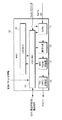
第1の実施形態に係る無線送信機1において、MAC部10は、図2に示すような構成を採る。すなわち、MAC部10への入力データは、buffer11に蓄積され、buffer11からはscheduler12の指示により適切なタイミングで適切なAC(Access Category)に属するデータが出力される。そして、buffer11から出力されたデータが暗号化部13により暗号化処理をされた後、MAC Header付加部14によってMAC Headerが付加される。その後、FCS付加部15によってFrame Check Sequenceが付加され、PHYに出力される。
In the
なお、図2において、controller16は、制御信号の処理や各ブロックの制御を行なうとともに、連結するMSDUの数「yi」を決定しbuffer11に通知する。また、scheduler12は、タイマに従い、各ブロックの制御を行なう。上記のcontroller16は、MAC制御部を構成する。
In FIG. 2, the
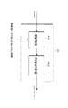
次に、MAC部10におけるbuffer11について説明する。図3は、buffer11の概略構成を示す図である。buffer11に入力されたDATAは、Mappinng to AC/STA11aによって、ACおよび送信宛のSTA(ステーション)に従ってマッピングされ、ACおよびSTA毎に用意されたキュー11b〜11eに蓄積される。つまり、異なるSTA宛のデータは異なるキューに蓄積され、さらに同じSTA宛でも異なるACに属するデータは異なるキューに蓄積されることとなる。
Next, the
scheduler12から送信可能を示す信号が入力された場合は、これら各キュー11b〜11eのうち、「yi」個以上データが蓄積されたものがCSMA/CA11f〜11iの動作により競争を行なう。ここで、「yi」および「i」は、自然数であり、i番目のキューで、yi個以上データが蓄積されたものが、送信信号の候補となることを示す。
When a signal indicating that transmission is possible is input from the
次に、上記競争の後、Internal Collision Resolution11kにより、複数キューの送信タイミングが重なった場合には、優先度の高いほうを送信する。また上記キュー11b〜11eに蓄積されたデータは、ACKにより受信成功が確認された後、消去されるものとする。なお、yiは、各キュー11b〜11eに決められた1無線パケットにおいて連結するMSDU数を決めるものである。
Next, after the above competition, when the transmission timings of a plurality of queues overlap with each other by the
続いて、図4において、図3に示したキュー11b〜11eの内部動作について説明する。キュー11b〜11eは、データを蓄積するメモリ11−1、閾値yiを超えるかどうかを判定する判定部11−2、判定部11−2の判定結果とscheduler12からの送信可能を示す信号に従いメモリの出力制御を行う出力制御部11−3、controller11からの指示に従いメモリ内容の削除などを行う制御部11−4からなる。なお、これらはハードウェアで構成される必要はなく、メモリおよびCPUおよびソフトウェアにより構成される場合もある。
Next, in FIG. 4, the internal operation of the
次に、buffer11の動作について説明する。ここでは、図5に示すように、AP(基地局)40から2台のSTA(端末:ステーション)であるSTA1(41)およびSTA2(42)にデータを送信するものとする。
Next, the operation of the
図6は、buffer11の動作を示すフローチャートである。まず、buffer11にデータが入力されると(ステップS1)、この入力データを、ACおよびSTA毎に用意されたキューに振り分ける(ステップS2)。続いて、ACKにより受信成功が確認された送信データをキューから削除し(ステップS3)、スケジューラ(scheduler12)から送信可能信号を受信したかどうかを判断する(ステップS4)。ステップS4において、スケジューラから送信可能信号を受信していない場合は、ステップS1へ移行し、スケジューラから送信可能信号を受信した場合は、各キューのうちyi個以上データが蓄積されたものがCSMA/CAの動作を行ない、送信データを選択する(ステップS5)。そして、ステップS5において選択されたデータを送信し(ステップS6)、ステップS1へ移行する。
FIG. 6 is a flowchart showing the operation of the
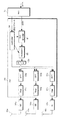
buffer11において、これらの動作を行なうことにより、図7(a)に示すように、MAC部10に入力されたSTA1(41)およびSTA2(42)向けのMSDUが、y1, y2個ずつ連結され、buffer11から出力されることになる。これにより、最終的に図7(b)に示すように、STA1(41)およびSTA2(42)向けにそれぞれ、y1個、y2個ずつPSDUを連結した無線パケットが送信されることとなる。
By performing these operations in the
なお、図7において、MSDU#n−mまたは、PSDU#n−mという形で数字が付加されているが、nは、STAn宛のデータ。mは、m個目のデータであることを示している。従って、図7では、宛先端末毎にMSDUをバッファリングし、1つの無線パケットでは、同一STA宛のMSDU(またはPSDU)を連結して送信していることを示している。ここで、y1,y2は、それぞれ、STA1にy1個のMSDUを連結して送信すること、STA2にy2個のMSDUを連結して送信することを示している。 In FIG. 7, numbers are added in the form of MSDU # n-m or PSDU # n-m, where n is data addressed to STAn. m represents the m-th data. Accordingly, FIG. 7 shows that MSDU is buffered for each destination terminal, and one wireless packet is transmitted by concatenating MSDU (or PSDU) addressed to the same STA. Here, y1 and y2 indicate that y1 MSDUs are concatenated and transmitted to STA1, and y2 MSDUs are concatenated and transmitted to STA2.
次に、図1におけるPHY部20について説明する。図8は、PHY部20の概略構成を示す図である。PHY部20は、図8に示すように、MAC部10から出力されたデータを、FEC encoder21においてPSDU単位で誤り訂正符号化する。つまり、FEC encoder21において、図9に示すように、各PSDUの最後尾に「tail bit」をつけ、PSDU毎に誤り訂正符号を終端させる。そして、複数のC−PSDUを作成し、modulator22に出力する。modulator22からの出力をIFFT23に出力し、IFFT23からの出力をfilter24に出力する。filter24から出力された信号は、無線送信部(RF)30において無線信号に変換され送信アンテナ40から送信される。
Next, the
このとき、MAC部10からPHY20のcontoroller25へは、図9に示すように、連結パラメータとして、length(連結後のPSDUの総ビット数)、PSDU#1 length(PSDU#1のビット数)、PSDU#2 length(PSDU#2のビット数)、PSDU#3 length(PSDU#3のビット数)を出力するものとする。また、FEC encoder21では、PSDU#1 length, PSDU#2 length, PSDU#3 lengthを基に、controller25からtailビット挿入位置を指示するものとする。また、controller25はlengthを基に各ブロックを制御し複数のPSDUを連結して1つの無線パケットを作成するものとする。
At this time, from the
続いて、図10において、FEC encoder21の内部動作について説明する。FEC encoder21は、上述の連結パラメータ(データユニット長情報)に基づいて、tailビットの挿入、つまり誤り訂正符号のための終端処理を行う終端処理部21aと、終端処理部21aから出力された信号を誤り訂正し出力する誤り訂正符号化部21bと、からなるものとする。
Next, the internal operation of the
なお、上記は3つのPSDUを連結する場合を例に挙げているが、これがs個(sは自然数)のPSDUを連結する場合であっても、手順は変わらない。 In the above, the case where three PSDUs are connected is taken as an example, but the procedure does not change even if this is the case where s (s is a natural number) PSDUs are connected.
このようにPHY部20を構成することにより、図11に示すように複数のMSDUを連結し、1つの無線パケットを生成することが可能となる。また、PSDU毎に誤り訂正符号を終端させておくことは、PSDU間で誤りが伝搬しにくくなる効果がある。
By configuring the
一方、図12に示すように、MAC部10から出力されたデータをFEC encoder21においてPSDUを連結した後、誤り訂正符号化しても良い。つまり、図12に示すように、FEC encoder21において、連結するPSDUの最後尾のみに「tail bit」をつけ、C−PSDUを1つ作成し、modulator22に出力する。modulator22からの出力をIFFT23に出力し、IFFT23からの出力をfilter24に出力する。そして、filter24から出力された信号は、無線送信部(RF)30において無線信号に変換され送信アンテナ40から送信される。
On the other hand, as shown in FIG. 12, the data output from the
このとき、MAC部10からPHY部20のcontoroller25へは、図12に示すように、連結パラメータとして、length(連結後のPSDUの総ビット数)を出力するものとする。また、FEC encoder21では、lengthを基に、controller25からtailビット挿入位置を指示するものとする。また、controller25は、lengthを基に各ブロックを制御し複数のPSDUを連結して1つの無線パケットを作成するものとする。
At this time, as shown in FIG. 12, length (total number of bits of PSDU after concatenation) is output from the
なお、上記は3つのPSDUを連結する場合を例に挙げているが、これがs個(sは自然数)のPSDUを連結する場合であっても、手順は変わらない。 In the above, the case where three PSDUs are connected is taken as an example, but the procedure does not change even if this is the case where s (s is a natural number) PSDUs are connected.
このようにPHY部20を構成することにより、図13に示すように複数のMSDUを連結し、1つの無線パケットを生成することが可能となる。
By configuring the
次に、MIMO方式を適用した場合のPHY部の構成について説明する。図14は、MIMO方式を採る無線送信機の概略構成を示す図である。図14に示すように、MAC部10から出力されたデータを、FEC encoder21において誤り訂正符号化する。これをmodulator22に出力し、modulator22からの出力を、S/P変換部120において、S/P変換(Serial to Parallel変換)する。なお、ここで述べるS/P変換とは、図15に示すようにOFDMシンボル毎に各アンテナへの割り当てを行なうことをいう。続いて、S/P変換部120からの出力をIFFT23a〜23cに出力し、各IFFT23a〜23cからの出力を、それぞれfilter24a〜24cに出力する。そして、各filter24a〜24cから出力された信号は、それぞれ無線送信部(RF)30a〜30cにおいて無線信号に変換され、各送信アンテナ40a〜40cから送信される。
Next, the configuration of the PHY unit when the MIMO scheme is applied will be described. FIG. 14 is a diagram illustrating a schematic configuration of a wireless transmitter employing the MIMO scheme. As shown in FIG. 14, the data output from the
なお、図14に示す無線送信機は、図8に示す無線送信機に対してMIMO方式を適用したものであり、上記のように、PSDU毎に誤り訂正符号化を行なっても良いし、連結したPSDUに対して誤り訂正符号化を行なっても良いものとする。 14 is obtained by applying the MIMO scheme to the wireless transmitter shown in FIG. 8. As described above, error correction coding may be performed for each PSDU, and the concatenation may be performed. It is assumed that error correction coding may be performed on the PSDU.
(第2の実施形態)
第2の実施形態では、複数のMSDUを連結するための、送信機におけるMAC部の機能を示す。また、本実施形態では、図16に示すように、AP40から1台のSTA1(41)にデータを送信する場合について述べる。ただし、AP40からSTA1(41)へは、2つのTS(Traffic Stream)が送信されているものとし、第2の実施形態においては、この2つのTSのACが異なるものとしている。一例として、図16では、TS#Aはパソコン向けのデータ伝送を示し、TS#BはTV向けの画像伝送を表しているものとする。MAC部の構成、およびPHY部の構成については、第1の実施形態に記載したものと同様とする。すなわち、MAC部は、図2に示すような構成を採る。図2に示すように、MAC部10への入力データは、buffer11に蓄積され、buffer11からはscheduler12の指示により適切なタイミングで適切なAC(Access Category)に属するデータが出力される。そして、buffer11から出力されたデータが暗号化部13により暗号化処理をされた後、MAC Header付加部14によってMAC Headerが付加される。その後、FCS付加部15によってFrame Check Sequenceが付加され、PHYに出力される。
(Second Embodiment)
In 2nd Embodiment, the function of the MAC part in a transmitter for connecting several MSDU is shown. Further, in the present embodiment, as shown in FIG. 16, a case where data is transmitted from the
なお、図2において、controller16は、制御信号の処理や各ブロックの制御を行なうとともに、連結するMSDUの数「yi」を決定しbuffer11に通知する。また、scheduler12は、タイマに従い、各ブロックの制御を行なう。
In FIG. 2, the
また、PHY部は、図8または図14に示すような構成を採る。図8に示す構成を採った場合には、PHY部20は、MAC部10から出力されたデータを、FEC encoder21においてPSDU単位で誤り訂正符号化する。つまり、FEC encoder21において、図9に示すように、各PSDUの最後尾に「tail bit」をつけ、PSDU毎に誤り訂正符号を終端させる。そして、複数のC−PSDUを作成し、modulator22に出力する。modulator22からの出力をIFFT23に出力し、IFFT23からの出力をfilter24に出力する。filter24から出力された信号は、無線送信部(RF)30において無線信号に変換され送信アンテナ40から送信される。
Further, the PHY unit adopts a configuration as shown in FIG. 8 or FIG. When the configuration shown in FIG. 8 is adopted, the
一方、図12に示すように、MAC部10から出力されたデータをFEC encoder21においてPSDUを連結した後、誤り訂正符号化しても良い。つまり、図12に示すように、FEC encoder21において、連結するPSDUの最後尾のみに「tail bit」をつけ、C−PSDUを1つ作成し、modulator22に出力する。modulator22からの出力をIFFT23に出力し、IFFT23からの出力をfilter24に出力する。そして、filter24から出力された信号は、無線送信部(RF)30において無線信号に変換され送信アンテナ40から送信される。
続いて、図14に示すMIMO方式を適用したPHY構成をとった場合について説明する。図14に示すように、MAC部10から出力されたデータを、FEC encoder21において、誤り訂正符号化する。これをmodulator22に出力し、modulator22からの出力を、S/P変換部120において、S/P変換(Serial to Parallel変換)する。なお、ここで述べるS/P変換とは、図15に示すようにOFDMシンボル毎に各アンテナへの割り当てを行うことをいう。続いて、S/P変換部120からの出力をIFFT23a〜23cに出力し、各IFFT23a〜23cからの出力を、それぞれfilter24a〜24cに出力する。そして、各filter24a〜24cから出力された信号は、それぞれ無線送信部(RF)30a〜30cにおいて無線信号に変換され、各送信アンテナ40a〜40cから送信される。
On the other hand, as shown in FIG. 12, the data output from the
Next, a case where a PHY configuration to which the MIMO scheme shown in FIG. 14 is applied will be described. As shown in FIG. 14, the data output from the
なお、図14に示す無線送信機は、図8に示す無線送信機に対してMIMO方式を適用したものであり、上記のように、PSDU毎に誤り訂正符号化を行っても良いし、連結したPSDUに対して誤り訂正符号化を行っても良いものとする。 14 is obtained by applying the MIMO scheme to the wireless transmitter shown in FIG. 8, and error correction coding may be performed for each PSDU as described above. It is assumed that error correction coding may be performed on the PSDU.
また、ここでは、図16に示すように、AP40から1台のSTA1(41)にデータを送信する場合について述べる。ただし、AP40からSTA1(41)へは、2つのTS(Traffic Stream)が送信されているものとし、第2の実施形態においては、この2つのTSのACが異なるものとしている。一例として、図16では、TS#Aはパソコン向けのデータ伝送を示し、TS#BはTV向けの画像伝送を表しているものとする。
Here, as shown in FIG. 16, a case will be described in which data is transmitted from the
次に、MAC部におけるbuffer11(図3参照)の動作について、図6に示すフローチャートを参照して説明する。まず、buffer11にデータが入力されると(ステップS1)、この入力されたデータをACおよびSTA毎に用意されたキューに振り分ける(ステップS2)。つまり本実施形態では、2つのTSはACが異なるので異なるキューに蓄積される。次に、ACKにより受信成功が確認された送信データをキューから削除し(ステップS3)、スケジューラ(scheduler12)から送信可能信号を受信したかどうかを判断する(ステップS4)。 Next, the operation of the buffer 11 (see FIG. 3) in the MAC unit will be described with reference to the flowchart shown in FIG. First, when data is input to the buffer 11 (step S1), the input data is distributed to a queue prepared for each AC and STA (step S2). That is, in this embodiment, two TSs are stored in different queues because the ACs are different. Next, the transmission data whose reception success is confirmed by the ACK is deleted from the queue (step S3), and it is determined whether or not a transmittable signal has been received from the scheduler (scheduler 12) (step S4).
ステップS4において、スケジューラから送信可能信号を受信していない場合は、ステップS1へ移行する一方、スケジューラから送信可能信号を受信した場合は、各キューのうち、yi個以上データが蓄積されたものがCSMA/CAの動作を行ない、送信データを選択する(ステップS5)。この後、ステップS5において選択されたデータを送信し(ステップS6)、ステップS1へ移行する。 In step S4, if a transmittable signal is not received from the scheduler, the process proceeds to step S1. On the other hand, if a transmittable signal is received from the scheduler, a queue in which at least yi pieces of data are accumulated is stored in each queue. CSMA / CA operation is performed to select transmission data (step S5). Thereafter, the data selected in step S5 is transmitted (step S6), and the process proceeds to step S1.
buffer11においてこれらの動作を行なうことにより、図17(a)に示すように、MAC部に入力されたTS#A,B向けのMSDUがy1,y2個ずつ連結され、buffer11から出力されることになる。これにより、最終的には図17(b)に示すように、TS#A,B向けにそれぞれ、y1個、y2個ずつPSDUを連結した無線パケットが送信されることとなる。なお、図17においては、MSDU#q−mまたは、PSDU#q−mという形でアルファベットおよび数字が付加されているが、qは、TS#qに相当するデータを意味し、mは、m個目のデータであることを示している。従って、図17では、TS毎にMSDUをバッファリングし、1つの無線パケットでは、同一TSのMSDU(またはPSDU)を連結して送信していることを示している。ちなみにy1,y2はTS#Aにy1個のMSDUを連結して送信すること、TS#Bにy2個のMSDUを連結して送信することを示している。
By performing these operations in the
以上説明したように、これらのPHY部、およびMAC部の構成を持つ送信機を備えた、アクセスポイント、ステーションにより、無線LANシステムを構築することにより、伝送効率の高いシステムをつくることができる。また、この無線LANシステムを用いることによって、高品位の動画像を伝送可能な画像伝送装置や、映像表示装置に画像伝送を行なうチューナーを作成することができる。 As described above, a system with high transmission efficiency can be created by constructing a wireless LAN system by using an access point and a station including a transmitter having the configuration of the PHY unit and the MAC unit. Further, by using this wireless LAN system, it is possible to create an image transmission device capable of transmitting a high-quality moving image and a tuner for transmitting an image to a video display device.
(第3の実施形態)
第3の実施形態では、複数のMSDUを連結するための、送信機におけるMAC部の機能を示す。第3の実施形態では、複数のMSDUを連結するための、送信機におけるMAC部の機能を示す。また本実施形態では、図18に示すように、AP40から1台のSTA1(41)にデータを送信する場合について述べる。ただし、AP40からSTA1(41)へは、2つのTS(Traffic Stream)が送信されているものとし、第2の実施形態においては、この2つのTSのACが同じものとしている。一例として、図18では、TS#B、TS#CはともにTV向けの画像伝送を表しているものとする。MAC部、およびPHY部の構成については、第1の実施形態に記載したものと同様と考える。すなわち、MAC部は、図2に示すような構成を採る。図2に示すように、MAC部10への入力データは、buffer11に蓄積され、buffer10からはscheduler12の指示により適切なタイミングで適切なAC(Access Category)に属するデータが出力される。そして、buffer11から出力されたデータが暗号化部13により暗号化処理をされた後、MAC Header付加部14によってMAC Headerが付加される。その後、FCS付加部15によってFrame Check Sequenceが付加され、PHYに出力される。
(Third embodiment)
In 3rd Embodiment, the function of the MAC part in a transmitter for connecting several MSDU is shown. In 3rd Embodiment, the function of the MAC part in a transmitter for connecting several MSDU is shown. In this embodiment, as shown in FIG. 18, a case where data is transmitted from the
なお、図2において、controller16は、制御信号の処理や各ブロックの制御を行なうとともに、連結するMSDUの数「yi」を決定しbuffer11に通知する。また、scheduler12は、タイマに従い、各ブロックの制御を行なう。
In FIG. 2, the
また、PHY部は、図8または図14に示すような構成をとる。図8に示す構成をとった場合には、PHY部20は、MAC部10から出力されたデータを、FEC encoder21においてPSDU単位で誤り訂正符号化する。つまり、FEC encoder21において、図9に示すように、各PSDUの最後尾に「tail bit」をつけ、PSDU毎に誤り訂正符号を終端させる。そして、複数のC−PSDUを作成し、modulator22に出力する。modulator22からの出力をIFFT23に出力し、IFFT23からの出力をfilter24に出力する。filter24から出力された信号は、無線送信部(RF)30において無線信号に変換され送信アンテナ40から送信される。
Further, the PHY unit has a configuration as shown in FIG. 8 or FIG. When the configuration shown in FIG. 8 is adopted, the
一方、図12に示すように、MAC部10から出力されたデータをFEC encoder21においてPSDUを連結した後、誤り訂正符号化しても良い。つまり、図12に示すように、FEC encoder21において、連結するPSDUの最後尾のみに「tail bit」をつけ、C−PSDUを1つ作成し、modulator22に出力する。modulator22からの出力をIFFT23に出力し、IFFT23からの出力をfilter24に出力する。そして、filter24から出力された信号は、無線送信部(RF)30において無線信号に変換され送信アンテナ40から送信される。
On the other hand, as shown in FIG. 12, the data output from the
続いて、図14に示すMIMO方式を適用したPHY構成をとった場合について説明する。図14に示すように、MAC部10から出力されたデータを、FEC encoder21において、誤り訂正符号化する。これをmodulator22に出力し、modulator22からの出力を、S/P変換部120において、S/P変換(Serial to Parallel変換)する。なお、ここで述べるS/P変換とは、図15に示すようにOFDMシンボル毎に各アンテナへの割り当てを行うことをいう。続いて、S/P変換部120からの出力をIFFT23a〜23cに出力し、各IFFT23a〜23cからの出力を、それぞれfilter24a〜24cに出力する。そして、各filter24a〜24cから出力された信号は、それぞれ無線送信部(RF)30a〜30cにおいて無線信号に変換され、各送信アンテナ40a〜40cから送信される。
なお、図14に示す無線送信機は、図8に示す無線送信機に対してMIMO方式を適用したものであり、上記のように、PSDU毎に誤り訂正符号化を行っても良いし、連結したPSDUに対して誤り訂正符号化を行っても良いものとする。
Next, a case where a PHY configuration to which the MIMO scheme shown in FIG. 14 is applied will be described. As shown in FIG. 14, the data output from the
14 is obtained by applying the MIMO scheme to the wireless transmitter shown in FIG. 8, and error correction coding may be performed for each PSDU as described above. It is assumed that error correction coding may be performed on the PSDU.
ここでは、図18に示すように、AP40から1台のSTA1(41)にデータを送信する場合について述べる。ただし、AP40からSTA1(41)へは、2つのTS(Traffic Stream)が送信されているものとし、第3の実施形態においては、この2つのTSのACが同じものとしている。一例として、図18では、TS#B、TS#CはともにTV向けの画像伝送を表しているものとする。また、MAC部におけるbuffer11(図3参照)の動作についても、第1の実施形態において、図6に示すフローチャートと同様である。
Here, as shown in FIG. 18, a case where data is transmitted from the
すなわち、図6に示すように、まず、buffer11にデータが入力されると(ステップS1)、この入力データを、ACおよびSTA毎に用意されたキューに振り分ける(ステップS2)。つまり、本実施形態では、2つのTSは、ACが同じなので同じキューに蓄積される。続いて、ACKにより受信成功が確認された送信データをキューから削除し(ステップS3)、スケジューラ(scheduler12)から送信可能信号を受信したかどうかを判断する(ステップS4)。ステップS4において、スケジューラから送信可能信号を受信していない場合は、ステップS1へ移行し、スケジューラから送信可能信号を受信した場合は、各キューのうちyi個以上データが蓄積されたものがCSMA/CAの動作を行ない、送信データを選択する(ステップS5)。そして、ステップS5において選択されたデータを送信し(ステップS6)、ステップS1へ移行する。 That is, as shown in FIG. 6, when data is input to buffer 11 (step S1), the input data is distributed to queues prepared for each AC and STA (step S2). That is, in this embodiment, two TSs are stored in the same queue because AC is the same. Subsequently, the transmission data whose reception success is confirmed by the ACK is deleted from the queue (step S3), and it is determined whether or not a transmittable signal has been received from the scheduler (scheduler 12) (step S4). In step S4, if a transmittable signal has not been received from the scheduler, the process proceeds to step S1, and if a transmittable signal has been received from the scheduler, a queue in which at least yi pieces of data have been accumulated is stored in each queue. CA operation is performed to select transmission data (step S5). Then, the data selected in step S5 is transmitted (step S6), and the process proceeds to step S1.
第3の実施形態において、buffer11が上記のような動作を行なうことにより、図19(a)に示すように、MAC部に入力されたTS#B,C向けのMSDUがy個連結され、buffer11から出力されることになる。これにより、最終的には図19(b)に示すようにTS#B,C向けにy個PSDUを連結した無線パケットが送信されることとなる。
In the third embodiment, when the
なお、図19においては、MSDU#q−mまたは、PSDU#q−mという形でアルファベットおよび数字が付加されているが、qは、TS#q宛のデータを意味し、mは、m個目のデータであることを示している。従って、図19では、TS#B、CのMSDUをバッファリングし、1つの無線パケットに、MSDU(またはPSDU)を連結して送信していることを示している。ここで、「y」は、y個のMSDUを連結して送信することを示している。 In FIG. 19, alphabets and numerals are added in the form of MSDU # q-m or PSDU # q-m, where q means data addressed to TS # q, and m is m pieces. Indicates eye data. Accordingly, FIG. 19 shows that MSDUs of TS # B and C are buffered, and MSDU (or PSDU) is concatenated and transmitted in one radio packet. Here, “y” indicates that y MSDUs are concatenated and transmitted.
なお、複数のSTAおよび複数のTSが混在した場合には、上記第1、2、3の実施形態を組み合わせることによって、MAC部およびPHY部が動作することが可能である。これらの組み合わせの動作は、上記第1、2、3の実施形態から導かれるものである。 When a plurality of STAs and a plurality of TSs are mixed, the MAC unit and the PHY unit can operate by combining the first, second, and third embodiments. The operation of these combinations is derived from the first, second, and third embodiments.
(第4の実施形態)
第4の実施形態では、複数のMSDUを連結する際の連結数yの決定方法について示す。特に、第4の実施形態においては、再送を考慮しない場合のQoSパラメータよりyを求めることとする。
(Fourth embodiment)
In the fourth embodiment, a method for determining the number of connections y when a plurality of MSDUs are connected will be described. In particular, in the fourth embodiment, y is obtained from a QoS parameter when retransmission is not considered.
まず、図20において、QoSパラメータの一例として、IEEE802.11eで定義されるTSPEC(Traffic Specification element)について示す。図20に示すように、IEEE802.11eでは、TS毎に要求される伝送条件がTSPECと呼ばれるパラメータ群で定義される。これらのうち代表的なものについて説明すると、Nominal MSDU Sizeは、"フレームサイズ(MAC部に入力されるデータサイズ)の平均値(単位はオクテット)"、Mean Data Rateは、"(MAC部に入力される)データレートの平均値"、Delay Boundは、"(アプリケーションが許容できる)許容遅延時間"を示している。これらTSPECにて規定されるパラメータは、アプリケーションから指定されるものである。 First, FIG. 20 shows a TSPEC (Traffic Specification Element) defined by IEEE 802.11e as an example of a QoS parameter. As shown in FIG. 20, in IEEE 802.11e, transmission conditions required for each TS are defined by a parameter group called TSPEC. A typical one of these will be explained. Nominal MSDU Size is “average value (unit is octet) of frame size (data size input to MAC section)”, and Mean Data Rate is “(input to MAC section). The average value of the data rate “, Delay Bound” indicates “allowable delay time (allowable by the application)”. These parameters defined by TSPEC are specified by the application.
図21は、第1の実施形態で図2を参照して説明したMAC部におけるcontroller16が、QoSパラメータに基づいて、MSDUの連結数「y」を決定する手順を示すフローチャートである。まず、AC毎に、n(1以上の実数)を決定する(ステップR1)。次に、AC毎に、x=Delay Bound/n[ms]を導出し(ステップR2)、AC毎のyを導出する(ステップR3)。そして、buffer11にAC毎のyを通知する(ステップR4)。
FIG. 21 is a flowchart illustrating a procedure in which the
次に、QoSパラメータの変更を検出し(ステップR5)、変更があればステップR2へ移行し、変更がなければステップR5の判断を繰り返す。ただし、複数の通信相手先STA、ACが同一のTSが存在する第3の実施形態に記載したような場合には、上記の
Delay Bound、
Mean Data Rate、
Nominal MSDU Size、は、それぞれ、
Delay Bound=min(Delay Bound1, Delay Bound 2, ・・・、Delay Bound n)、
Mean Data Rate=add(Mean Data Rate 1, Mean Data Rate 2, ・・・、Mean Data Rate n)、
Nominal MSDU Size=ave(Nominal MSDU Size1、Nominal MSDU Size2、・・・、Nominal MSDU Sizen)、
で表されるものとする。
Next, a change in the QoS parameter is detected (step R5). If there is a change, the process proceeds to step R2, and if there is no change, the determination in step R5 is repeated. However, in the case described in the third embodiment in which a plurality of communication partner STAs and ACs have the same TS, the above-described Delay Bound,
Mean Data Rate,
Nominal MSDU Size,
Delay Bound = min (Delay Bound 1, Delay Bound 2,..., Delay Bound n),
Mean Data Rate = add (
Nominal MSDU Size = ave (Nominal MSDU Size1, Nominal MSDU Size2,..., Nominal MSDU Size)
It shall be represented by
なお、「min()」は、カッコ内の要素の最小値を求める関数を表わし、add()は、カッコ内の要素の合計を求める関数を表わす。また、ave()は、カッコ内の要素の平均値を求める関数を表している。また、
Delay Bound r,
Mean Data Rate r,
Nominal MSDU Size r、は、それぞれ、
"r番目のTSの(アプリケーションが許容できる)許容遅延時間"、
"r番目のTSの(MACに入力される)データレートの平均値"、
"r番目のTSのフレームサイズ(MACに入力されるデータサイズ)の平均値(単位はオクテット)"を示している。なお、rは、自然数を表している。なお、図21では、ACごとにyを決定したが、通信相手先STA、AC毎に用意したキュー毎にyを決定することもできる。
“Min ()” represents a function for obtaining a minimum value of elements in parentheses, and add () represents a function for obtaining a sum of elements in parentheses. Further, ave () represents a function for obtaining an average value of elements in parentheses. Also,
Delay Bound r,
Mean Data Rater,
Nominal MSDU Size,
“allowable delay time of r-th TS (allowable by application)”,
"Average value of data rate (input to MAC) of r-th TS",
“Average value (unit: octet) of frame size (data size input to MAC) of r-th TS”. Note that r represents a natural number. In FIG. 21, y is determined for each AC. However, y may be determined for each queue prepared for each communication partner STA and AC.
上記のような手順を用いて、MSDU連結数yを決定した例を、図22、および図23に示す。図22では、
n=4、
Delay Bound=1[ms]、
Nominal MSDU Size=2000[オクテット]、
Mean Data Rate=48M[bit/sec]、と仮定している。これらのパラメータを、図21に示す手順に適用すると、
x=Delay Bound/n=0.25[ms]、
y=Mean Data Rate*x/(Nominal MSDU Size*8)=3[個]、
となり、
図22に示すように、0.25ms毎に、MSDUを3個連結した無線パケットを送信することになる。
An example in which the MSDU concatenation number y is determined using the above procedure is shown in FIG. 22 and FIG. In FIG.
n = 4,
Delay Bound = 1 [ms],
Nominal MSDU Size = 2000 [octet],
It is assumed that Mean Data Rate = 48M [bit / sec]. Applying these parameters to the procedure shown in FIG.
x = Delay Bound / n = 0.25 [ms],
y = Mean Data Rate * x / (Nominal MSDU Size * 8) = 3 [pieces]
And
As shown in FIG. 22, a radio packet in which three MSDUs are concatenated is transmitted every 0.25 ms.
同様に、図23では、
n=2、
Delay Bound=1[ms]、
Nominal MSDU Size=2000[オクテット]、Mean Data Rate=48M[bit/sec]、と仮定している。これらのパラメータを、図21に示す手順に適用すると、
x=Delay Bound/n=0.5[ms]、
y=Mean Data Rate*x/(Nominal MSDU Size*8)=6[個]、
となり、
図23に示すように、0.5ms毎に、MSDUを6個連結した無線パケットを送信することになる。
Similarly, in FIG.
n = 2,
Delay Bound = 1 [ms],
It is assumed that Nominal MSDU Size = 2000 [octets] and Mean Data Rate = 48 M [bit / sec]. Applying these parameters to the procedure shown in FIG.
x = Delay Bound / n = 0.5 [ms],
y = Mean Data Rate * x / (Nominal MSDU Size * 8) = 6 [pieces]
And
As shown in FIG. 23, a radio packet in which six MSDUs are concatenated is transmitted every 0.5 ms.
このように、同じQoSパラメータを持つTSでも、nを調整することにより、伝送遅延を小さくしたり、伝送効率を上げたりすることができる。なお、値nをアプリケーションや、データのPER(Packet Error Rate)、伝搬路の状態により変更する方法も考えられる。また、上記MSDUの連結数yは、AC毎に決定されるが、手順に関しては図21に示す方法を適用するだけで足りる。また、本実施例ではアプリケーションから送信されるデータが一定レートであると仮定しているが、キューに保存されているデータの保存時間を基にタイムアウト処理を行うことにより可変レートのアプリケーションに対応したり、処理遅延時間を短くするために、送信パケットの種類(ACKなど)によって、上記MSDUの連結数yを変えることなどが考えられる。 As described above, even with TS having the same QoS parameter, by adjusting n, it is possible to reduce the transmission delay or increase the transmission efficiency. A method of changing the value n according to the application, the PER (Packet Error Rate) of data, and the state of the propagation path is also conceivable. Further, the number y of MSDU connections is determined for each AC, but it is sufficient to apply the method shown in FIG. 21 for the procedure. In this embodiment, it is assumed that the data transmitted from the application is at a constant rate. However, the time-out process is performed based on the storage time of the data stored in the queue, so that the variable rate application is supported. In order to shorten the processing delay time, it is conceivable to change the connection number y of the MSDUs depending on the type of transmission packet (such as ACK).
(第5の実施形態)
第5の実施形態では、複数のMSDUを連結する際の連結数yの決定方法について示す。特に、第5の実施形態においては、再送を考慮した場合のQoSパラメータおよびキューに蓄積されたデータの再送回数よりyを求める。
(Fifth embodiment)
In the fifth embodiment, a method for determining the number of connections y when connecting a plurality of MSDUs will be described. In particular, in the fifth embodiment, y is obtained from the QoS parameters when retransmission is considered and the number of retransmissions of data stored in the queue.
図24は、第1の実施形態で図2を参照して説明したMAC部におけるcontroller16が、QoSパラメータに基づいてMSDUの連結数yを決定する手順を示すフローチャートである。まず、キュー毎にni(1以上の実数)を決める(ステップP1)。次に、キュー毎にxi=Delay Bound/ni[ms]を導出し(ステップP2)、キュー毎のyiを導出する(ステップP3)。次に、miが0であるか、0より大きいか同かを判断し(ステップP4)、mi>0である場合は、yi=yi+piとして(ステップP5)、ステップP6へ移行する。一方、ステップP4において、mi=0である場合は、ステップP6へ移行する。
FIG. 24 is a flowchart illustrating a procedure in which the
次に、buffer11にキュー毎のyiを通知し(ステップP6)、QoSパラメータおよびmiの変更を検出し(ステップP7)、変更があればステップP2へ移行し、変更がなければステップP7における判断を繰り返す。
Next, the
ここで、上記、ni、yi、mi、piは、i番目のキューにおけるn,y(MSDUの連結数),m(キューに蓄積されている再送データのうち最大の再送回数),p(キューに蓄積されている再送データ数)の値を示している。また上記ステップP3において「yi」を導出する一例としては、
yi=roundup(Mean Data Rate*xi/(Nominal MSDU Size*8))
が考えられる。なお上記式で関数roundup()は、カッコ内の数を整数に切り上げる処理を示す。
Here, ni, yi, mi, and pi are n, y (the number of connected MSDUs), m (the maximum number of retransmissions among the retransmission data stored in the queue), p (queue) in the i-th queue. The number of retransmitted data stored in the As an example of deriving “yi” in step P3,
yi = roundup (Mean Data Rate * xi / (Nominal MSDU Size * 8))
Can be considered. In the above formula, the function roundup () indicates a process of rounding up the number in parentheses to an integer.
ただし、複数の通信相手先STA、ACが同一のTSが存在する第3の実施形態に記載したような場合には、上記の
Delay Bound、
Mean Data Rate、
Nominal MSDU Size、は、それぞれ、
Delay Bound=min(Delay Bound1, Delay Bound 2, ・・・、Delay Bound n)、
Mean Data Rate=add(Mean Data Rate 1, Mean Data Rate 2, ・・・、Mean Data Rate n)、
Nominal MSDU Size=ave(Nominal MSDU Size1、Nominal MSDU Size2、・・・、Nominal MSDU Sizen)、
で表されるものとする。
However, in the case described in the third embodiment in which a plurality of communication partner STAs and ACs have the same TS, the above-described Delay Bound,
Mean Data Rate,
Nominal MSDU Size,
Delay Bound = min (Delay Bound 1, Delay Bound 2,..., Delay Bound n),
Mean Data Rate = add (
Nominal MSDU Size = ave (Nominal MSDU Size1, Nominal MSDU Size2,..., Nominal MSDU Size)
It shall be represented by
なお、min()は、カッコ内の要素の最小値を求める関数を表わし、add()は、カッコ内の要素の合計を求める関数を表わす。ave()は、カッコ内の要素の平均値を求める関数を表している。また、
Delay Bound r,
Mean Data Rate r,
Nominal MSDU Size r、は、それぞれ、
"r番目のTSの(アプリケーションが許容できる)許容遅延時間"、
"r番目のTSの(MACに入力される)データレートの平均値"、
"r番目のTSのフレームサイズ(MACに入力されるデータサイズ)の平均値(単位はオクテット)"、を示している。
Note that min () represents a function for obtaining the minimum value of elements in parentheses, and add () represents a function for obtaining the sum of elements in parentheses. ave () represents a function for obtaining an average value of elements in parentheses. Also,
Delay Bound r,
Mean Data Rater,
Nominal MSDU Size,
“allowable delay time of r-th TS (allowable by application)”,
"Average value of data rate (input to MAC) of r-th TS",
“Average value (unit: octet) of the frame size (data size input to the MAC) of the r-th TS”.
図25は、上記の手順を用いて、MSDU連結数yを決定した一例を示す図である。図25では、
n=4、
Delay Bound=1[ms]、Nominal MSDU Size=2000[オクテット]、
Mean Data Rate=48M[bit/sec]、と仮定している。また、PSDU#1、PSDU#7、PSDU#8がそれぞれ一回ずつ誤ると仮定している。これらのパラメータを、図24に示す手順に適用すると、
x=Delay Bound/n=0.25[ms]、
y=Mean Data Rate*x/(Nominal MSDU Size*8)=3[個](再送なしの場合)、
y=3+p(再送ありの場合)、
となり、
図22に示すように、0.25ms毎に、再送データがない場合にはMSDUを3個連結した無線パケットが、再送データがある場合には、再送MSDUと新規のMSDU3個を連結して送信することになる。
FIG. 25 is a diagram illustrating an example in which the MSDU concatenation number y is determined using the above procedure. In FIG.
n = 4,
Delay Bound = 1 [ms], Nominal MSDU Size = 2000 [octet],
It is assumed that Mean Data Rate = 48M [bit / sec]. Also, it is assumed that
x = Delay Bound / n = 0.25 [ms],
y = Mean Data Rate * x / (Nominal MSDU Size * 8) = 3 [pieces] (when there is no retransmission),
y = 3 + p (with retransmission),
And
As shown in FIG. 22, every 0.25 ms, when there is no retransmission data, a wireless packet in which three MSDUs are concatenated, and when there is retransmission data, the retransmit MSDU and three new MSDUs are concatenated and transmitted Will do.
(第6の実施形態)
第6の実施形態では、複数のMSDUを連結する際の連結数yの決定方法について示す。特に、第6の実施形態においては、再送を考慮した場合のQoSパラメータおよびキューに蓄積されたデータの再送回数よりyを求める。
(Sixth embodiment)
In the sixth embodiment, a method for determining the number of connections y when connecting a plurality of MSDUs will be described. In particular, in the sixth embodiment, y is obtained from the QoS parameters when retransmission is considered and the number of retransmissions of data stored in the queue.
図26は、第1の実施形態で図2を参照して説明したMAC部におけるcontroller16が、QoSパラメータに基づいてMSDUの連結数yを決定する手順を示すフローチャートである。まず、キュー毎にni(1以上の実数)を決める(ステップQ1)。次に、miが0であるか0より大きいかどうかについての判定を行ない(ステップQ2)、mi>0ならばステップQ5においてyi=0としてステップQ6へ移行する。
FIG. 26 is a flowchart illustrating a procedure in which the
一方、ステップQ2において、mi=0ならば、キュー毎にxi=Delay Bound/ni[ms]を導出し(ステップQ3)、キュー毎のyiを導出する(ステップQ4)。 On the other hand, if mi = 0 in step Q2, xi = Delay Bound / ni [ms] is derived for each queue (step Q3), and yi for each queue is derived (step Q4).
次に、buffer11にキュー毎のyiを通知し(ステップQ6)、QoSパラメータおよびmiの変更を検出し(ステップQ7)、変更があればステップQ2へ移行し、変更がなければステップQ7における判断を繰り返す。ここで、上記、ni、yi、miは、i番目のキューにおけるn,y(MSDUの連結数),m(キューに蓄積されている再送データのうち最大の再送回数)の値を示している。 Next, yi for each queue is notified to buffer 11 (step Q6), and a change in the QoS parameters and mi is detected (step Q7). If there is a change, the process proceeds to step Q2. repeat. Here, ni, yi, and mi indicate the values of n, y (the number of connected MSDUs) and m (the maximum number of retransmissions among the retransmission data stored in the queue) in the i-th queue. .
また、上記ステップQ4において、yiを導出する一例としては、
yi=roundup(Mean Data Rate*xi/(Nominal MSDU Size*8))
が考えられる。なお、上記式で関数roundup()は、カッコ内の数を整数に切り上げる処理を示す。
In addition, as an example of deriving yi in step Q4,
yi = roundup (Mean Data Rate * xi / (Nominal MSDU Size * 8))
Can be considered. Note that the function roundup () in the above formula indicates processing for rounding up the number in parentheses to an integer.
ただし、複数のTSが存在する第3の実施形態に記載したような場合には、上記の
Delay Bound、
Mean Data Rate、
Nominal MSDU Size、は、それぞれ、
Delay Bound=min(Delay Bound1, Delay Bound 2, ・・・、Delay Bound n)、
Mean Data Rate=add(Mean Data Rate 1, Mean Data Rate 2, ・・・、Mean Data Rate n)、
Nominal MSDU Size=ave(Nominal MSDU Size1、Nominal MSDU Size2、・・・、Nominal MSDU Sizen)、
で表されるものとする。
However, in the case described in the third embodiment where a plurality of TSs exist, the above-described Delay Bound,
Mean Data Rate,
Nominal MSDU Size,
Delay Bound = min (Delay Bound 1, Delay Bound 2,..., Delay Bound n),
Mean Data Rate = add (
Nominal MSDU Size = ave (Nominal MSDU Size1, Nominal MSDU Size2,..., Nominal MSDU Size)
It shall be represented by
なお、min()は、カッコ内の要素の最小値を求める関数を表わし、add()は、カッコ内の要素の合計を求める関数を表わす。ave()は、カッコ内の要素の平均値を求める関数を表している。また、
Delay Bound r,
Mean Data Rate r,
Nominal MSDU Size r、は、それぞれ、
"r番目のTSの(アプリケーションが許容できる)許容遅延時間"、
"r番目のTSの(MACに入力される)データレートの平均値"、
"r番目のTSのフレームサイズ(MACに入力されるデータサイズ)の平均値(単位はオクテット)"を示している。
Note that min () represents a function for obtaining the minimum value of elements in parentheses, and add () represents a function for obtaining the sum of elements in parentheses. ave () represents a function for obtaining an average value of elements in parentheses. Also,
Delay Bound r,
Mean Data Rater,
Nominal MSDU Size,
“allowable delay time of r-th TS (allowable by application)”,
"Average value of data rate (input to MAC) of r-th TS",
“Average value (unit: octet) of frame size (data size input to MAC) of r-th TS”.
図27は、上記手順を用いて、MSDU連結数yを決定した一例を示す図である。図27では、
n=4、
Delay Bound=1[ms]、Nominal MSDU Size=2000[オクテット]、
Mean Data Rate=48M[bit/sec]、と仮定している。また、PSDU#1、PSDU#7、PSDU#8がそれぞれ一回ずつ誤ると仮定している。これらのパラメータを、図26に示す手順に適用すると、
x=Delay Bound/n=0.25[ms]、
y=Mean Data Rate*x/(Nominal MSDU Size*8)=3[個](再送なしの場合)、
y=0(再送ありの場合)、
となり、
図22に示すように、0.25ms毎に、再送データがない場合にはMSDUを3個連結した無線パケットが、再送データがある場合には、再送MSDUを連結して送信することになる。
FIG. 27 is a diagram illustrating an example in which the MSDU concatenation number y is determined using the above procedure. In FIG.
n = 4,
Delay Bound = 1 [ms], Nominal MSDU Size = 2000 [octet],
It is assumed that Mean Data Rate = 48M [bit / sec]. Also, it is assumed that
x = Delay Bound / n = 0.25 [ms],
y = Mean Data Rate * x / (Nominal MSDU Size * 8) = 3 [pieces] (when there is no retransmission),
y = 0 (in case of resending),
And
As shown in FIG. 22, every 0.25 ms, when there is no retransmission data, a wireless packet in which three MSDUs are concatenated is transmitted, and when there is retransmission data, retransmission MSDUs are concatenated and transmitted.
(第7の実施形態)
第7の実施形態では、複数のMSDUを連結する際の連結数yの決定方法について示す。特に、第7の実施形態においては、再送を考慮した場合のQoSパラメータおよびキューに蓄積されたデータの再送回数よりyを求める。
(Seventh embodiment)
In the seventh embodiment, a method for determining the number of connections y when connecting a plurality of MSDUs will be described. In particular, in the seventh embodiment, y is obtained from the QoS parameters when retransmission is considered and the number of times of retransmission of data stored in the queue.
図28は、第1の実施形態で図2を参照して説明したMAC部におけるcontroller16が、QoSパラメータに基づいてMSDUの連結数yを決定する手順を示すフローチャートである。まず、キュー毎にmiに従いni(1以上の実数)を決める(ステップK1)。次に、キュー毎にxi=Delay Bound/ni[ms]を導出し(ステップK2)、キュー毎のyiを導出する(ステップK3)。次に、buffer11にキュー毎のyiを通知し(ステップK4)、QoSパラメータおよびmiの変更を検出する(ステップK5)。ステップK5において、QoSパラメータおよびmiの変更があればステップK1へ移行し、変更がなければステップK5における判断を繰り返す。ここで、上記、ni、yi、miは、i番目のキューにおけるn,y(MSDUの連結数),m(キューに蓄積されている再送データのうち最大の再送回数)の値を示している。
FIG. 28 is a flowchart illustrating a procedure in which the
なお、上記ステップK1において、miに従いniを決定する方法の一例としては、
mi>0のときは、ni=4*mi、
mi=0のときには、ni=4、
のように、miに従って単調増加させる方法が考えられる。
また、上記ステップK3において、yiを導出する一例としては、
yi=roundup(Mean Data Rate*xi/(Nominal MSDU Size*8))、
が考えられる。なお上記式で関数roundup()は、カッコ内の数を整数に切り上げる処理を示す。
In addition, as an example of the method of determining ni according to mi in the above step K1,
When mi> 0, ni = 4 * mi,
When mi = 0, ni = 4,
Thus, a method of increasing monotonously according to mi can be considered.
As an example of deriving yi in step K3,
yi = roundup (Mean Data Rate * xi / (Nominal MSDU Size * 8)),
Can be considered. In the above formula, the function roundup () indicates a process of rounding up the number in parentheses to an integer.
ただし、複数の通信相手先STA、ACが同一のTSが存在する第3の実施形態に記載したような場合には、上記の
Delay Bound、
Mean Data Rate、
Nominal MSDU Size、は、それぞれ、
Delay Bound=min(Delay Bound1, Delay Bound 2, ・・・、Delay Bound n)、
Mean Data Rate=add(Mean Data Rate 1, Mean Data Rate 2, ・・・、Mean Data Rate n)、
Nominal MSDU Size=ave(Nominal MSDU Size1、Nominal MSDU Size2、・・・、Nominal MSDU Sizen)、
で表されるものとする。
However, in the case described in the third embodiment in which a plurality of communication partner STAs and ACs have the same TS, the above-described Delay Bound,
Mean Data Rate,
Nominal MSDU Size,
Delay Bound = min (Delay Bound 1, Delay Bound 2,..., Delay Bound n),
Mean Data Rate = add (
Nominal MSDU Size = ave (Nominal MSDU Size1, Nominal MSDU Size2,..., Nominal MSDU Size)
It shall be represented by
なお、min()は、カッコ内の要素の最小値を求める関数を表わし、add()は、カッコ内の要素の合計を求める関数を表わす。ave()は、カッコ内の要素の平均値を求める関数を表している。また、
Delay Bound r,
Mean Data Rate r,
Nominal MSDU Size r、は、それぞれ、
"r番目のTSの(アプリケーションが許容できる)許容遅延時間"、
"r番目のTSの(MACに入力される)データレートの平均値"、
"r番目のTSのフレームサイズ(MACに入力されるデータサイズ)の平均値(単位はオクテット)"を示している。
Note that min () represents a function for obtaining the minimum value of elements in parentheses, and add () represents a function for obtaining the sum of elements in parentheses. ave () represents a function for obtaining an average value of elements in parentheses. Also,
Delay Bound r,
Mean Data Rater,
Nominal MSDU Size,
“allowable delay time of r-th TS (allowable by application)”,
"Average value of data rate (input to MAC) of r-th TS",
“Average value (unit: octet) of frame size (data size input to MAC) of r-th TS”.
図29は、上記手順を用いて、MSDU連結数yを決定した一例を示す図である。図29では、
Delay Bound=1[ms]、
Nominal MSDU Size=2000[オクテット]、
Mean Data Rate=48M[bit/sec]、と仮定している。また、PSDU#1が3回、PSDU#7、PSDU#8がそれぞれ一回ずつ誤ると仮定している。これらのパラメータを、図28に示す手順に適用すると、
y=Mean Data Rate*0.25/(Nominal MSDU Size*8)=3[個](再送なし(m=0)の場合)、
y=3(m=1の場合)、
y=roundup(1.5)=2(m=2の場合)、
y=1(m=3の場合)、
となり、
図29に示すように、mに応じて再送MSDUと新規MSDUを連結して送信することになる。図29からもわかるとおり、図28に示す方法でyを決定すると、mが大きい(伝送遅延が大きな問題となる)場合には、伝送遅延を小さくすることを優先し、mが小さい(伝送遅延が大きな問題とならない)場合には、連結MSDU数yを大きくし伝送効率を優先していることがわかる。
FIG. 29 is a diagram illustrating an example in which the MSDU concatenation number y is determined using the above procedure. In FIG.
Delay Bound = 1 [ms],
Nominal MSDU Size = 2000 [octet],
It is assumed that Mean Data Rate = 48M [bit / sec]. Further, it is assumed that
y = Mean Data Rate * 0.25 / (Nominal MSDU Size * 8) = 3 [pieces] (in the case of no retransmission (m = 0)),
y = 3 (when m = 1),
y = roundup (1.5) = 2 (when m = 2),
y = 1 (when m = 3),
And
As shown in FIG. 29, retransmission MSDU and new MSDU are concatenated and transmitted according to m. As can be seen from FIG. 29, when y is determined by the method shown in FIG. 28, when m is large (transmission delay is a big problem), priority is given to reducing the transmission delay and m is small (transmission delay). If this is not a big problem, it can be seen that the number of concatenated MSDUs y is increased to give priority to transmission efficiency.
ここで、参考として図30に、図29同様、
n=4、
Delay Bound=1[ms]、
Nominal MSDU Size=2000[オクテット]、
Mean Data Rate=48M[bit/sec]、と仮定、また、PSDU#1が3回、PSDU#7、PSDU#8がそれぞれ一回ずつ誤ると仮定した場合の一例を示す。これらのパラメータを、図24の手順に適用すると、図30に示すような動作となり、第7の実施形態提案の方式(図28)を適用した場合と比較して、伝送効率は高いものの、誤りの連続したPSDU(PSDU#1)の伝送遅延が大きくなってしまうことがわかる。
Here, for reference, FIG. 30 is similar to FIG.
n = 4,
Delay Bound = 1 [ms],
Nominal MSDU Size = 2000 [octet],
Assuming that Mean Data Rate = 48M [bit / sec], and assuming that
なお、上記の第5、6、6の実施形態において、yiを決定するアルゴリズムについて説明したが、それぞれ伝送効率の向上を重視したアルゴリズム、伝送遅延の低減を重視したアルゴリズムなど、適する状況が異なることから、ACによって適用するアルゴリズムを変更したり、PER(Packet Error Rate)や伝搬路状況によって適用するアルゴリズムを変更したりすることが考えられる。 In the fifth, sixth, and sixth embodiments, the algorithm for determining yi has been described. However, suitable conditions such as an algorithm that emphasizes improvement of transmission efficiency and an algorithm that emphasizes reduction of transmission delay are different. Therefore, it is conceivable to change the algorithm applied by AC, or to change the algorithm applied depending on PER (Packet Error Rate) and propagation path conditions.
1 無線送信機
10 MAC部
20 PHY部
30 無線送信部(RF)
40 送信アンテナ
11 buffer
11−1 メモリ
11−2 判定部
11−3 出力制御部
11−4 制御部
11a Mappinng to AC/STA
11b〜11e キュー
11f〜11i CSMA/CA
11k Internal Collision Resolution
12 scheduler
13 暗号化部
14 MAC Header付加部
15 FCS付加部
16 (MAC)controller
21 FECencoder
21a 終端処理部
21b 誤り訂正符号化部
22 modulator
23 IFFT
24 filter
25 (PHY)controller
40 AP
41 STA1
42 STA2
120 S/P変換部
DESCRIPTION OF
40 Transmitting
11-1 Memory 11-2 Determination Unit 11-3 Output Control Unit 11-4
11b-
11k Internal Collision Resolution
12 scheduler
13
21 FECencoder
21a
23 IFFT
24 filter
25 (PHY) controller
40 AP
41 STA1
42 STA2
120 S / P converter
Claims (21)
通信相手先の無線通信機およびQoSクラスに対応して割当てられた複数のキューと、
前記各キューに蓄積されたデータユニット数が、一つの無線パケットに含まれるデータユニット数として定められた閾値を超えたかどうかを判定する判定部と、
前記判定の結果、いずれかの前記キューにおいて蓄積されたデータユニット数が前記閾値を超えた場合、そのキューに対して蓄積したデータユニットを出力するよう制御する出力制御部と、を備えることを特徴とする無線送信機。 A MAC unit that performs transmission control, a PHY unit that performs electrical conversion and mechanical work for sending data output from the MAC unit to a communication line, and data output from the PHY unit as a radio signal A wireless transmitter that performs wireless transmission using a wireless packet that includes a plurality of data units.
A plurality of queues assigned corresponding to the wireless communication device and QoS class of the communication partner;
A determination unit that determines whether or not the number of data units accumulated in each queue exceeds a threshold defined as the number of data units included in one wireless packet;
An output control unit that controls to output the data units stored in the queue when the number of data units stored in any of the queues exceeds the threshold as a result of the determination. A wireless transmitter.
QoSクラスの異なるアプリケーション毎に定められるQoSパラメータと、QoSクラスの異なるアプリケーションおよび通信相手先の無線通信機毎の待機中の再送データユニットの再送回数とに基づいて、一つの無線パケットに含まれるデータユニット数として定められた閾値を決定するMAC制御部を備えることを特徴とする無線送信機。 A MAC unit that performs transmission control, a PHY unit that performs electrical conversion and mechanical work for sending data output from the MAC unit to a communication line, and data output from the PHY unit as a radio signal A wireless transmitter that performs wireless transmission using a wireless packet that includes a plurality of data units.
Data included in one wireless packet based on QoS parameters determined for each application having a different QoS class, and the number of retransmissions of a waiting retransmission data unit for each wireless communication device of a communication partner and another application having a different QoS class A wireless transmitter comprising a MAC control unit for determining a threshold value determined as the number of units.
QoSクラスの異なるアプリケーション毎に定められるQoSパラメータに基づいて、一つの無線パケットに含まれるデータユニット数として定められた閾値を決定し、この閾値に、前記QoSクラスの異なるアプリケーションおよび通信相手先の無線通信機毎の待機中の再送データユニットの数を加算して得られた数値を、一つの無線パケットに含まれるデータユニット数とすることを特徴とする請求項12記載の無線送信機。 The MAC control unit
Based on a QoS parameter determined for each application having a different QoS class, a threshold value determined as the number of data units included in one wireless packet is determined, and the application having a different QoS class and the wireless communication partner are used as the threshold value. 13. The wireless transmitter according to claim 12, wherein a numerical value obtained by adding the number of waiting retransmission data units for each communication device is the number of data units included in one wireless packet.
QoSクラスの異なるアプリケーション毎に定められるQoSパラメータに基づいて、一つの無線パケットに含まれるデータユニット数として定められた閾値を決定し、前記QoSクラスの異なるアプリケーションおよび通信相手先の無線通信機毎の待機中の再送データユニットの最大の再送回数が0である場合は、一つの無線パケットに含まれるデータユニット数を、前記決定した閾値とする一方、
前記QoSクラスの異なるアプリケーションおよび通信相手先の無線通信機毎の待機中の再送データユニットの最大の再送回数が0でない場合は、前記閾値を0とすることを特徴とする請求項12記載の無線送信機。 The MAC control unit
Based on the QoS parameters determined for each application having different QoS classes, a threshold value determined as the number of data units included in one wireless packet is determined, and for each application having a different QoS class and each wireless communication device of the communication partner When the maximum number of retransmissions of waiting retransmission data units is 0, the number of data units included in one wireless packet is set as the determined threshold value,
13. The wireless communication according to claim 12, wherein the threshold is set to 0 when the maximum number of retransmissions of waiting retransmission data units for each application and communication partner wireless communication device with different QoS classes is not 0. Transmitter.
前記データユニットの最大の再送回数が大きいほど、前記閾値を小さくし、前記データユニットの最大の再送回数が小さいほど、前記閾値を大きくすることを特徴とする請求項12記載の無線送信機。 The MAC control unit
13. The radio transmitter according to claim 12, wherein the threshold is decreased as the maximum number of retransmissions of the data unit is increased, and the threshold is increased as the maximum number of retransmissions of the data unit is decreased.
A tuner comprising the wireless transmitter according to any one of claims 9 to 16.
Priority Applications (1)
| Application Number | Priority Date | Filing Date | Title |
|---|---|---|---|
| JP2004320374A JP4367706B2 (en) | 2004-11-04 | 2004-11-04 | Wireless transmission method, wireless transmitter, and wireless LAN system |
Applications Claiming Priority (1)
| Application Number | Priority Date | Filing Date | Title |
|---|---|---|---|
| JP2004320374A JP4367706B2 (en) | 2004-11-04 | 2004-11-04 | Wireless transmission method, wireless transmitter, and wireless LAN system |
Publications (2)
| Publication Number | Publication Date |
|---|---|
| JP2006135486A JP2006135486A (en) | 2006-05-25 |
| JP4367706B2 true JP4367706B2 (en) | 2009-11-18 |
Family
ID=36728653
Family Applications (1)
| Application Number | Title | Priority Date | Filing Date |
|---|---|---|---|
| JP2004320374A Expired - Fee Related JP4367706B2 (en) | 2004-11-04 | 2004-11-04 | Wireless transmission method, wireless transmitter, and wireless LAN system |
Country Status (1)
| Country | Link |
|---|---|
| JP (1) | JP4367706B2 (en) |
Families Citing this family (4)
| Publication number | Priority date | Publication date | Assignee | Title |
|---|---|---|---|---|
| US8135015B2 (en) * | 2009-03-27 | 2012-03-13 | Qualcomm Incorporated | System and method of transmitting and receiving data frames |
| US9602627B2 (en) | 2009-06-29 | 2017-03-21 | Qualcomm Incorporated | Technique for setting network communication parameters |
| JP7173140B2 (en) | 2018-06-20 | 2022-11-16 | 富士通株式会社 | Transmission device and buffer control method |
| JP7571660B2 (en) | 2021-05-19 | 2024-10-23 | 株式会社デンソー | COMMUNICATION CONTROL DEVICE, COMMUNICATION CONTROL METHOD, AND COMMUNICATION CONTROL PROGRAM |
-
2004
- 2004-11-04 JP JP2004320374A patent/JP4367706B2/en not_active Expired - Fee Related
Also Published As
| Publication number | Publication date |
|---|---|
| JP2006135486A (en) | 2006-05-25 |
Similar Documents
| Publication | Publication Date | Title |
|---|---|---|
| JP4440037B2 (en) | Communication apparatus and communication method | |
| RU2367096C2 (en) | Advanced block acknowledgement | |
| JP4005974B2 (en) | COMMUNICATION DEVICE, COMMUNICATION METHOD, AND COMMUNICATION SYSTEM | |
| KR100762071B1 (en) | Method for acknowledging data packets in network including plurality of stations connected by common wireless channel | |
| US11387965B2 (en) | Method for replying with acknowledgement frame, apparatus, and data transmission system | |
| JP4331088B2 (en) | Communication apparatus and communication method | |
| CN113411831A (en) | Data transmission method and device | |
| US9166734B2 (en) | Method and device for frame aggregation transmission of wireless network system | |
| CN101399634B (en) | Wireless transmission device, wireless transmission method, wireless communication system, and program | |
| US8554148B2 (en) | Data transmission/reception apparatus and method for wireless communication system | |
| JP4901681B2 (en) | Wireless communication apparatus and wireless communication method | |
| JP2009164751A (en) | Wireless communication apparatus, wireless communication method, and program | |
| JP4367706B2 (en) | Wireless transmission method, wireless transmitter, and wireless LAN system | |
| JP2006352897A (en) | COMMUNICATION DEVICE, COMMUNICATION METHOD, AND COMMUNICATION SYSTEM | |
| Saif et al. | Impact of aggregation headers on aggregating small MSDUs in 802.11 n WLANs | |
| JP2006304238A (en) | MAC control method and MAC control apparatus | |
| Hajlaoui et al. | Analytical study of frame aggregation in error-prone channels | |
| Zhai et al. | A distributed packet concatenation scheme for sensor and ad hoc networks | |
| Sharon et al. | A new aggregation based scheduling method for rapidly changing IEEE 802.11 ac wireless channels | |
| Chosokabe et al. | A channel adaptive hybrid aggregation scheme for next generation wireless LAN | |
| JP4444244B2 (en) | Communication device | |
| Skordoulis et al. | Analysis of Concatenation and Packing Mechanisms in IEEE 802.11 n | |
| Sharon et al. | Comparison between TCP scheduling strategies in IEEE 802.11 ac based wireless networks | |
| US20250220714A1 (en) | Data Unit Delivery for Relay Communications | |
| JP4422148B2 (en) | Information communication apparatus, information communication method and program |
Legal Events
| Date | Code | Title | Description |
|---|---|---|---|
| A621 | Written request for application examination |
Free format text: JAPANESE INTERMEDIATE CODE: A621 Effective date: 20070302 |
|
| A977 | Report on retrieval |
Free format text: JAPANESE INTERMEDIATE CODE: A971007 Effective date: 20081215 |
|
| A131 | Notification of reasons for refusal |
Free format text: JAPANESE INTERMEDIATE CODE: A131 Effective date: 20090106 |
|
| A521 | Written amendment |
Free format text: JAPANESE INTERMEDIATE CODE: A523 Effective date: 20090212 |
|
| TRDD | Decision of grant or rejection written | ||
| A01 | Written decision to grant a patent or to grant a registration (utility model) |
Free format text: JAPANESE INTERMEDIATE CODE: A01 Effective date: 20090818 |
|
| A01 | Written decision to grant a patent or to grant a registration (utility model) |
Free format text: JAPANESE INTERMEDIATE CODE: A01 |
|
| A61 | First payment of annual fees (during grant procedure) |
Free format text: JAPANESE INTERMEDIATE CODE: A61 Effective date: 20090819 |
|
| R150 | Certificate of patent or registration of utility model |
Free format text: JAPANESE INTERMEDIATE CODE: R150 |
|
| FPAY | Renewal fee payment (event date is renewal date of database) |
Free format text: PAYMENT UNTIL: 20120904 Year of fee payment: 3 |
|
| FPAY | Renewal fee payment (event date is renewal date of database) |
Free format text: PAYMENT UNTIL: 20130904 Year of fee payment: 4 |
|
| LAPS | Cancellation because of no payment of annual fees |