JP4369727B2 - Exhaust purification device control method - Google Patents
Exhaust purification device control method Download PDFInfo
- Publication number
- JP4369727B2 JP4369727B2 JP2003375229A JP2003375229A JP4369727B2 JP 4369727 B2 JP4369727 B2 JP 4369727B2 JP 2003375229 A JP2003375229 A JP 2003375229A JP 2003375229 A JP2003375229 A JP 2003375229A JP 4369727 B2 JP4369727 B2 JP 4369727B2
- Authority
- JP
- Japan
- Prior art keywords
- exhaust
- temperature
- injection
- control
- control device
- Prior art date
- Legal status (The legal status is an assumption and is not a legal conclusion. Google has not performed a legal analysis and makes no representation as to the accuracy of the status listed.)
- Expired - Lifetime
Links
Images
Classifications
-
- Y—GENERAL TAGGING OF NEW TECHNOLOGICAL DEVELOPMENTS; GENERAL TAGGING OF CROSS-SECTIONAL TECHNOLOGIES SPANNING OVER SEVERAL SECTIONS OF THE IPC; TECHNICAL SUBJECTS COVERED BY FORMER USPC CROSS-REFERENCE ART COLLECTIONS [XRACs] AND DIGESTS
- Y02—TECHNOLOGIES OR APPLICATIONS FOR MITIGATION OR ADAPTATION AGAINST CLIMATE CHANGE
- Y02A—TECHNOLOGIES FOR ADAPTATION TO CLIMATE CHANGE
- Y02A50/00—TECHNOLOGIES FOR ADAPTATION TO CLIMATE CHANGE in human health protection, e.g. against extreme weather
- Y02A50/20—Air quality improvement or preservation, e.g. vehicle emission control or emission reduction by using catalytic converters
-
- Y—GENERAL TAGGING OF NEW TECHNOLOGICAL DEVELOPMENTS; GENERAL TAGGING OF CROSS-SECTIONAL TECHNOLOGIES SPANNING OVER SEVERAL SECTIONS OF THE IPC; TECHNICAL SUBJECTS COVERED BY FORMER USPC CROSS-REFERENCE ART COLLECTIONS [XRACs] AND DIGESTS
- Y02—TECHNOLOGIES OR APPLICATIONS FOR MITIGATION OR ADAPTATION AGAINST CLIMATE CHANGE
- Y02T—CLIMATE CHANGE MITIGATION TECHNOLOGIES RELATED TO TRANSPORTATION
- Y02T10/00—Road transport of goods or passengers
- Y02T10/10—Internal combustion engine [ICE] based vehicles
- Y02T10/40—Engine management systems
Landscapes
- Control Of Throttle Valves Provided In The Intake System Or In The Exhaust System (AREA)
- Control Of Vehicle Engines Or Engines For Specific Uses (AREA)
- Processes For Solid Components From Exhaust (AREA)
- Filtering Of Dispersed Particles In Gases (AREA)
- Exhaust Gas After Treatment (AREA)
- Electrical Control Of Air Or Fuel Supplied To Internal-Combustion Engine (AREA)
- Combined Controls Of Internal Combustion Engines (AREA)
Description
本発明は、排気浄化装置の制御方法に関するものである。 The present invention relates to a method for controlling an exhaust emission control device.
ディーゼルエンジンから排出されるパティキュレート(Particulate Matter:粒子状物質)は、炭素質から成る煤と、高沸点炭化水素成分から成るSOF分(Soluble Organic Fraction:可溶性有機成分)とを主成分とし、更に微量のサルフェート(ミスト状硫酸成分)を含んだ組成を成すものであるが、この種のパティキュレートの低減対策としては、排気ガスが流通する排気管の途中に、パティキュレートフィルタを装備することが従来より行われている。 Particulate matter (particulate matter) discharged from a diesel engine is mainly composed of soot made of carbonaceous matter and SOF content (Soluble Organic Fraction) made of high-boiling hydrocarbon components. The composition contains a small amount of sulfate (mist-like sulfuric acid component). As a measure to reduce this type of particulates, a particulate filter is installed in the middle of the exhaust pipe through which the exhaust gas flows. It has been done conventionally.
この種のパティキュレートフィルタは、コージェライト等のセラミックから成る多孔質のハニカム構造となっており、格子状に区画された各流路の入口が交互に目封じされ、入口が目封じされていない流路については、その出口が目封じされるようになっており、各流路を区画する多孔質薄壁を透過した排気ガスのみが下流側へ排出されるようにしてある。 This type of particulate filter has a porous honeycomb structure made of a ceramic such as cordierite, and the inlets of the flow paths partitioned in a lattice pattern are alternately sealed, and the inlets are not sealed. About the flow path, the exit is sealed, and only the exhaust gas which permeate | transmitted the porous thin wall which divides each flow path is discharged | emitted downstream.
そして、排気ガス中のパティキュレートは、前記多孔質薄壁の内側表面に捕集されて堆積するので、目詰まりにより排気抵抗が増加しないうちにパティキュレートを適宜に燃焼除去してパティキュレートフィルタの再生を図る必要があるが、通常のディーゼルエンジンの運転状態においては、パティキュレートが自己燃焼するほどの高い排気温度が得られる機会が少ないため、例えばアルミナに白金を担持させたものに適宜な量のセリウム等の希土類元素を添加して成る酸化触媒を一体的に担持させた触媒再生型のパティキュレートフィルタの実用化が進められている。 Then, the particulates in the exhaust gas are collected and deposited on the inner surface of the porous thin wall, so that the particulates are appropriately burned and removed before the exhaust resistance increases due to clogging. It is necessary to regenerate, but in normal diesel engine operating conditions, there are few opportunities to obtain exhaust temperatures that are high enough for the particulates to self-combust. For example, an appropriate amount for alumina loaded with platinum A catalyst regeneration type particulate filter in which an oxidation catalyst formed by adding a rare earth element such as cerium is integrally supported is being put to practical use.
即ち、このような触媒再生型のパティキュレートフィルタを採用すれば、捕集されたパティキュレートの酸化反応が促進されて着火温度が低下し、従来より低い排気温度でもパティキュレートを燃焼除去することが可能となるのである。 That is, if such a catalyst regeneration type particulate filter is employed, the oxidation reaction of the collected particulates is promoted to lower the ignition temperature, and the particulates can be burned and removed even at an exhaust temperature lower than the conventional one. It becomes possible.
ただし、この種のパティキュレートフィルタにおいては、排気温度の低いアイドリング状態が長く継続した場合に触媒床温度が低下して活性が下がり、排気ガス中に含まれる未燃燃料の炭化水素がパティキュレートフィルタの酸化触媒上で酸化処理しきれずに徐々に溜まってしまうので、長時間のアイドリング状態を経た後に車両が走行を開始して排気温度が上昇した際に、パティキュレートフィルタに溜まった炭化水素が急激に酸化反応を起こして白煙を生じる虞れがあることが懸念されている。 However, in this type of particulate filter, when the idling state where the exhaust temperature is low continues for a long time, the catalyst bed temperature is lowered and the activity is lowered, and the hydrocarbon of unburned fuel contained in the exhaust gas is removed. As the exhaust gas temperature rises after the vehicle has started running after a long period of idling, hydrocarbons accumulated in the particulate filter suddenly accumulate. There is a concern that white smoke may be generated due to an oxidation reaction.
因みに、このようにアイドリング状態が長く継続してしまうような事態としては、例えば、都心を走る路線バスが激しい渋滞に巻き込まれてしまったような場合や、終点まで到着した路線バスが次の折り返し運行に備えてエンジンをかけたまま待機しているような場合(乗客が着座して待っている場合に冷房等の空調を作動させ続ける必要がある)、或いは、長距離輸送トラックが高速道路等のパーキングでエンジンをかけたまま休憩(仮眠)している場合(冷房等の空調を作動させ続けたい場合)等が想定される。 By the way, as a situation where the idling state continues for a long time as described above, for example, when a route bus running in the city center is caught in a heavy traffic jam, or a route bus that arrives at the end point turns back to the next If you are waiting with the engine running in preparation (when passengers are seated and waiting, it is necessary to continue operating air conditioning such as cooling), or long-distance transportation trucks are on highways, etc. It is assumed that there is a break (nap) with the engine running in the parking (when it is desired to continue operating an air conditioner such as cooling).
そして、前述した如きアイドリング状態が長く継続した後の走行開始時における排気ガスの白煙化の対策としては、所定時間以上のアイドリング状態の継続が確認された時に、パティキュレートフィルタより上流側で排気ガスを所定温度以上に昇温する排気昇温手段を作動させ、アイドリング状態が長く継続して大量の炭化水素がパティキュレートフィルタに溜まる前に炭化水素を酸化処理してしまうという昇温制御を用いたものが既に提案されている(例えば先行出願1「特願2002−88508号明細書」、先行出願2「特願2002−296173号明細書」参照)。
And as a countermeasure against exhaust gas whitening at the start of running after the idling state as described above continues for a long time, when it is confirmed that the idling state continues for a predetermined time or longer, the exhaust gas is exhausted upstream from the particulate filter. The exhaust temperature raising means that raises the gas to a predetermined temperature or more is activated, and the temperature rise control is used so that the hydrocarbon is oxidized before the idling state continues for a long time and a large amount of hydrocarbon accumulates in the particulate filter. (See, for example, prior application 1 “Japanese Patent Application No. 2002-88508”,
しかしながら、このような昇温制御を車両に実施するに際し、例えば、車両がクレーン車や消防自動車等の特装車(特別装備車)であるような場合には、アイドリング停車した状態でエンジン駆動により補機を使用することになるので、このような補機の使用時に昇温制御が自動的に実行されてしまうと、エンジンの運転状態が急変して補機の作動不良を招く虞れがある。 However, when such temperature raising control is performed on the vehicle, for example, when the vehicle is a specially equipped vehicle (special equipment vehicle) such as a crane truck or a fire engine, the auxiliary machine is driven by the engine while idling is stopped. Therefore, if the temperature raising control is automatically executed when such an auxiliary machine is used, the operating state of the engine may change suddenly, leading to a malfunction of the auxiliary machine.
即ち、上記の先行出願1や先行出願2にも説明されている通り、アイドリング状態での排気ガスの温度及び流量は大幅に低下しているため、メイン噴射の一回当たりの噴射量を増加することで通常のアイドリング時より回転数を上げ、これによりエネルギー投入量を増やして排気ガスの温度及び流量を昇温制御に適したレベルまで引き上げる制御を加える必要があるため、このように通常のアイドリング時より回転数が上昇してしまうことで補機の作動に運転者の予期しない変動が生じることが懸念された。
That is, as explained in the prior application 1 and the
本発明は上述の実情に鑑みてなしたもので、特装車における補機の使用時に排気ガスの白煙化を防ぐための昇温制御の実施により前記補機に作動不良が起こらないようにすることを目的としている。 The present invention has been made in view of the above-described circumstances, and prevents the auxiliary equipment from malfunctioning by performing a temperature rise control to prevent the exhaust gas from becoming white smoke when using the auxiliary equipment in a specially equipped vehicle. It is an object.
本発明は、エンジン動力をパワーテイクオフ装置を介しアイドリング状態で取り出して補機を駆動し得るようにした特装車に適用するための排気浄化装置の制御方法であって、排気管の途中に装備された触媒再生型のパティキュレートフィルタと、該パティキュレートフィルタより上流側で排気ガスを所定温度以上に昇温する排気昇温手段と、所定時間以上のアイドリング状態の継続が確認された時に前記排気昇温手段を作動せしめる昇温制御指令を出力する制御装置とを備え、パワーテイクオフ装置のスイッチがオンで且つ操作入力が検知された場合に限り前記制御装置から昇温制御指令を出力させないことを特徴とするものである。 The present invention is a control method of an exhaust purification device for application to a specially equipped vehicle that can take out engine power in an idling state via a power take-off device and drive an auxiliary machine, and is provided in the middle of an exhaust pipe A catalyst regeneration type particulate filter, an exhaust temperature raising means for raising the exhaust gas temperature to a predetermined temperature or more upstream from the particulate filter, and the exhaust gas temperature raising means when it is confirmed that the idling state continues for a predetermined time or more. and characterized by a control device for outputting allowed to heat-up control command actuating means, does not output the temperature increase control command from the control device only when the switch of the power take-off device and the operation input oN is detected To do.
より具体的に本発明を実施するに際しては、例えば、エンジンの各気筒に対し燃料を噴射する燃料噴射装置を排気昇温手段として採用し、該燃料噴射装置に対し通常のアイドリング時より回転数を上げるべくメイン噴射の一回当たりの噴射量を増加し且つ該メイン噴射直後の燃焼可能なタイミングでアフタ噴射を追加する燃料噴射指令を昇温制御指令として制御装置から出力させることが好ましい。 In carrying out the present invention more specifically, for example, a fuel injection device that injects fuel into each cylinder of the engine is adopted as an exhaust temperature raising means, and the rotational speed of the fuel injection device is increased from that during normal idling. It is preferable to output from the control device as a temperature increase control command a fuel injection command that increases the injection amount per main injection and increases after-injection at a combustible timing immediately after the main injection.
而して、このようにすれば、パワーテイクオフ装置のスイッチをオンにして補機に対する操作を実行した時点で制御装置から排気昇温手段に向けた昇温制御指令の出力が阻止されるので、エンジン動力をパワーテイクオフ装置を介しアイドリング状態で取り出して補機を操作している状況下で回転数の上昇やアフタ噴射の追加等といった昇温制御がかからなくなり、エンジンの運転状態が急変して補機の作動不良を招くといった事態が起こらなくなる。 And Thus, in this way to lever, the output of the temperature increase control command directed from the controller at the time of performing operations on and switch on the power take-off device auxiliary to the exhaust Atsushi Nobori means is prevented In the situation where the engine power is taken out in idling state via the power take-off device and the auxiliary machine is operated, the temperature rise control such as increase in the number of revolutions and addition of after-injection is not applied, and the operating state of the engine changes suddenly. As a result, malfunctions of the auxiliary machinery will not occur.
他方、補機による作業を行わない通常のアイドリング状態、或いは、パワーテイクオフ装置のスイッチがオンになっていても実質的な補機への操作が実行されていないアイドリング状態が所定時間以上継続された場合には、制御装置からの昇温制御指令により排気昇温手段が作動されて排気ガスが所定温度以上に昇温され、これによりパティキュレートフィルタの触媒床温度が高められて酸化触媒の活性化が図られる結果、アイドリング状態が長く継続して大量の炭化水素がパティキュレートフィルタに溜められてしまう前に炭化水素が酸化処理されて放出される。 On the other hand, a normal idling state in which no operation is performed by the auxiliary machine, or an idling state in which the operation of the auxiliary machine is not substantially executed even when the power take-off device is switched on is continued for a predetermined time or more. In this case, the exhaust gas temperature raising means is activated by the temperature raising control command from the control device, and the exhaust gas is heated to a predetermined temperature or higher, thereby raising the catalyst bed temperature of the particulate filter and activating the oxidation catalyst. As a result, before the idling state continues for a long time and a large amount of hydrocarbons are stored in the particulate filter, the hydrocarbons are oxidized and released.
ここで、燃料噴射装置を排気昇温手段として採用している場合について補足説明しておくと、このようにした場合には、メイン噴射の一回当たりの噴射量が増加されて回転数が上げられることによりエネルギー投入量が増えて排気温度の上昇が図られ、しかも、アフタ噴射による燃料が出力に転換され難いタイミングで燃焼することによりエンジンの熱効率が下がり、燃料の発熱量のうちの動力に利用されない熱量が増えて排気温度の上昇が図られることになる。 Here, a supplementary explanation will be given of the case where the fuel injection device is employed as the exhaust gas temperature raising means. In such a case, the injection amount per one injection of the main injection is increased and the rotational speed is increased. As a result, the amount of energy input increases, the exhaust temperature rises, and the fuel from the after-injection burns at a timing when it is difficult to convert to the output. The amount of heat that is not used increases and the exhaust temperature rises.
尚、このような白煙対策の昇温制御は、パワーテイクオフ装置のスイッチがオンになっていても実質的な補機への操作が実行されない限り実行されるので、闇雲にパワーテイクオフ装置のスイッチがオンになった時点から昇温制御を阻止するよりも効率良くパティキュレートフィルタ内の炭化水素を放出させることが可能となる。 Such temperature rise control for white smoke countermeasures is executed as long as no substantial operation is performed even if the power take-off device is switched on. It becomes possible to release the hydrocarbons in the particulate filter more efficiently than when temperature increase control is prevented from when the is turned on.
更に、本発明においては、排気流量を絞り込むことが可能な排気絞り手段を排気昇温手段として併用し、該排気絞り手段に対しエンジン側における回転数の上昇とアフタ噴射の追加に併せて排気流量を絞り込む開度指令信号を昇温制御指令として制御装置から出力させることが好ましく、このようにすれば、前述したエンジン側における回転数の上昇とアフタ噴射の追加に併せて排気絞り手段により排気流量が絞り込まれる結果、その上流側の排気ガスが昇温されることで排気温度が上昇されると共に、排気抵抗が高まることにより気筒内に比較的温度の低い吸気が流入し難くなって比較的温度の高い排気ガスの残留量が増加し、この比較的温度の高い排気ガスを多く含む気筒内の空気が次の圧縮行程で圧縮されて爆発行程を迎えることでも更なる排気温度の上昇が図られることになる。 Furthermore, in the present invention, an exhaust throttle means capable of reducing the exhaust flow rate is used in combination as an exhaust temperature raising means, and the exhaust flow rate is increased in accordance with the increase in the rotational speed on the engine side and the addition of after-injection with respect to the exhaust throttle means. It is preferable to output an opening degree command signal for narrowing the engine from the control device as a temperature increase control command . In this way, the exhaust flow rate is increased by the exhaust throttle means in conjunction with the increase in the engine speed and the addition of after-injection. As a result, the exhaust gas temperature is raised by raising the temperature of the exhaust gas on the upstream side, and the exhaust resistance is increased, so that the intake air having a relatively low temperature does not easily flow into the cylinder. The amount of high exhaust gas residue increases, and the air in the cylinder, which contains a relatively high temperature of exhaust gas, is compressed in the next compression stroke and reaches the explosion stroke. Increase in the exhaust temperature is being the reduced made.
上記した本発明の排気浄化装置の制御方法によれば、エンジン動力をパワーテイクオフ装置を介しアイドリング状態で取り出して補機を操作している状況下で回転数の上昇やアフタ噴射の追加等による昇温制御がかからないようにすることができるので、この昇温制御によりエンジンの運転状態が急変して補機の作動不良を招くといった事態を確実に回避することができ、しかも、パワーテイクオフ装置のスイッチがオンになっていても実質的な補機への操作が実行されない限り昇温制御が極力実行されるようになっているので、補機の作動不良を確実に回避しながらも白煙の発生確率を極力低下させることができるという優れた効果を奏し得る。 According to the control method of the exhaust purification apparatus of the present invention described above, the engine power is taken out in an idling state via the power take-off device, and the engine speed is increased by increasing the rotational speed or adding after-injection under the condition that the auxiliary machine is operated. Since the temperature control can be prevented, it is possible to reliably avoid a situation in which the operating state of the engine suddenly changes and causes the malfunction of the auxiliary machine due to the temperature increase control, and the switch of the power take-off device Even if is turned on, temperature rise control is performed as much as possible unless substantial operation to the auxiliary equipment is performed, so white smoke is generated while reliably preventing malfunction of the auxiliary equipment An excellent effect that the probability can be reduced as much as possible can be obtained.
以下本発明の実施の形態を図面を参照しつつ説明する。 Embodiments of the present invention will be described below with reference to the drawings.
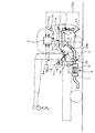
図1及び図2は本発明を実施する形態の一例を示すもので、本形態例においては、図1に例示している如きクレーン車等の特装車に関し、そのディーゼルエンジン1(エンジン)から排気マニホールド2を介して排出された排気ガス3が流通している排気管4のマフラ5内に、酸化触媒を一体的に担持して成る触媒再生型のパティキュレートフィルタ6を収容させるようにしており、該パティキュレートフィルタ6を抱持するフィルタケース7がマフラ5の外筒を成すようになっている。
FIG. 1 and FIG. 2 show an example of an embodiment for carrying out the present invention. In this embodiment, a specially equipped vehicle such as a crane vehicle as illustrated in FIG. 1 is connected to the exhaust manifold from the diesel engine 1 (engine). A catalyst regeneration type
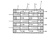
即ち、このフィルタケース7の内部には、図2に拡大して示す如きパティキュレートフィルタ6が収容されており、このパティキュレートフィルタ6は、セラミックから成る多孔質のハニカム構造となっており、格子状に区画された各流路6aの入口が交互に目封じされ、入口が目封じされていない流路6aについては、その出口が目封じされるようになっており、各流路6aを区画する多孔質薄壁6bを透過した排気ガス3のみが下流側へ排出されるようにしてある。
That is, a
そして、フィルタケース7の入口部分には、パティキュレートフィルタ6に導入される排気ガス3の温度を触媒床温度の代用値として計測する温度センサ8が装備されており、該温度センサ8の検出信号8aがエンジン制御コンピュータ(ECU:Electronic Control Unit)を成す制御装置9に対し入力されるようになっている。
A temperature sensor 8 that measures the temperature of the
この制御装置9は、エンジン制御コンピュータを兼ねていることから燃料の噴射に関する制御も担うようになっており、より具体的には、アクセル開度をディーゼルエンジン1の負荷として検出するアクセルセンサ11(負荷センサ)からのアクセル開度信号11aと、ディーゼルエンジン1の機関回転数を検出する回転センサ12からの回転数信号12aとに基づき、ディーゼルエンジン1の各気筒に燃料を噴射する燃料噴射装置10に向け燃料噴射信号10aが出力されるようになっている。
Since this
ここで、前記燃料噴射装置10は、各気筒毎に装備される複数のインジェクタにより構成されており、これら各インジェクタの電磁弁が前記燃料噴射信号10aにより適宜に開弁制御されて燃料の噴射タイミング及び噴射量が適切に制御されるようになっている。
Here, the fuel injection device 10 is composed of a plurality of injectors provided for each cylinder, and the solenoid valve of each injector is appropriately controlled to be opened by the
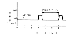
そして、前記制御装置9では、アクセル開度信号11a及び回転数信号12aに基づき通常モードの燃料噴射信号10aが決定されるようになっている一方、後述するアイドリング判定手段により所定時間以上のアイドリング状態の継続が確認された時に、前記温度センサ8の検出温度に基づき所定のインターバル(30分〜4時間程度)を決定して間欠的に通常モードから昇温モードへの切り替えを行い、この昇温モードに切り替わった際には、図3に示す如く、通常のアイドリング時(約450rpm程度)より回転数を上げる制御(450〜1500rpm程度)を実行するべく圧縮上死点(クランク角0゜)付近で行われていたメイン噴射の一回当たりの噴射量を増加すると共に、該メイン噴射直後の燃焼可能なタイミングでアフタ噴射を追加するような噴射パターンの燃料噴射信号10a(燃料噴射指令)が昇温制御指令として出力されるようになっている。
In the
また、パティキュレートフィルタ6より上流側の適宜位置には、排気管4の流路を適宜な開度に絞り込む開度調整可能な排気ブレーキ20が装備されており、該排気ブレーキ20は、制御装置9からの開度指令信号20aにより開度制御されるようになっているが、本形態例においては、制御装置9にて昇温モードが選択された際に、排気ブレーキ20に対し本来の作動から独立した別の作動を指令し、後述する如き排気温度を上げるための排気絞り手段として排気ブレーキ20を活用できるようにしてある。
An appropriate position upstream of the
また、特に図1中には図示していないが、先に説明したアクセルセンサ11,回転センサ12のほか、ギヤ位置がニュートラルポジションにあることを検出するニュートラルスイッチ、サイドブレーキが引かれていることを検出するサイドブレーキスイッチ、車速を検出する車速センサの夫々からの検出信号も制御装置9に入力されるようになっており、これらの検出信号に基づき車両がアイドリング状態にあるか否かが前記制御装置9にて判定されるようになっている。
Although not specifically shown in FIG. 1, in addition to the
即ち、前記制御装置9においては、回転センサ12により比較的低い所定の回転数域であることが確認され、アクセルセンサ11によりアクセルオフ(負荷が零)が確認され、ニュートラルスイッチによりギヤ位置がニュートラルポジションにあることが確認され、サイドブレーキスイッチによりサイドブレーキが引かれていることが確認され、車速センサにより車速が零であることが確認された時に現在の運転状態がアイドリング状態にあると判定するようになっている。
That is, in the
尚、アイドリング状態の判定にあたっては、これらのセンサ類やスイッチ類からの信号を必ずしも全て必要とするわけではなく、少なくとも回転センサ12と、アクセルセンサ11,ニュートラルスイッチ,サイドブレーキスイッチ,車速センサの何れかとの組み合わせによりアイドリング判定手段を構成することが可能であり、また、より確実な判定を行う目的でクラッチ信号等の更なる別の信号を考慮するようにしても良い。
Note that the determination of the idling state does not necessarily require all signals from these sensors and switches, and at least one of the
そして、図1に図示している如き特装車にあっては、変速機13の側面にパワーテイクオフ装置14が装備されており、変速機13の副軸歯車からギヤトレーンを介して動力を取り出し得るようにしてあり、この変速機13から取り出された動力は、パワーテイクオフ装置14の出力軸から油圧ポンプ等の補機15へと出力されるようになっているが、その出力のオン・オフについては、パワーテイクオフ装置14の内部にて行われるようになっている。
In the specially equipped vehicle as shown in FIG. 1, a power take-
ただし、エンジン動力の取り出し方については、前述した如きトランスミッションPTO方式のほか、変速機13の前部のフライホイールに設けた歯車から動力を取り出すようにしたフライホイールPTO方式等といった各種の方式を採用することが可能である。
However, in addition to the transmission PTO method as described above, various methods such as a flywheel PTO method in which power is extracted from the gear provided on the flywheel at the front of the
他方、キャブ内のインストルメントパネルには、エンジン動力をパワーテイクオフ装置14を介し取り出して補機15を駆動し得るようにするためのPTOスイッチ16が配設されており、該PTOスイッチ16をオンとすることでオン信号16aを受けた制御装置9からPTO指令信号14aがパワーテイクオフ装置14へ向け出力されて該パワーテイクオフ装置14の出力がオンとなる一方、キャブ外に別途設置した外部アクセル17が有効となるようにしてある。
On the other hand, the instrument panel in the cab is provided with a
即ち、この外部アクセル17は、キャブ外の特装用アクセルセンサ18を特装用レバー19で操作するように構成されており、PTOスイッチ16のオン時に特装用アクセルセンサ18からの外部アクセル開度信号18aがディーゼルエンジン1の制御信号として制御装置9内で電気的に有効化され、キャブ内でアクセルペダルを踏まなくてもディーゼルエンジン1の回転数をキャブ外で制御できるようになっている。
That is, the
ただし、制御装置9においては、PTOスイッチ16のオン信号16aが入力され且つ外部アクセル開度信号18aに基づき外部アクセル17の特装用レバー19の実質的な操作入力が検知されている条件下、つまり、エンジン動力をパワーテイクオフ装置14を介しアイドリング状態で取り出して補機15を操作している条件下で再生モードの燃料噴射信号10a(昇温制御指令)が出力されないようにインターロックがかかるようになっており、より具体的には、燃焼噴射制御が通常モードから再生モードへ切り替わらないようになっている。
However, in the
尚、ここでは補機15に対する操作を外部アクセル17で行う場合を例示しているが、補機15をキャブ内のアクセルペダルで操作することが可能な特装車や、補機15をキャブ内のアイドルボリューム(暖機運転時等にアイドリング回転数を手動で調整するためのスロットルボタン)で操作することが可能な特装車の場合には、これらアクセルペダルやアイドルボリュームの操作信号を前記外部アクセル開度信号18aと同様に扱い、これを補機15に対する操作入力として制御装置9内で検知させるようにすれば良い。
Here, the case where the operation with respect to the
而して、このように排気浄化装置を構成すれば、キャブ内のPTOスイッチ16をオンにして補機15に対する操作(外部アクセル17の特装用レバー19の操作)を実行した時点で制御装置9から燃料噴射装置10に向けた再生モードの燃料噴射信号10a(昇温制御指令)の出力が阻止されるので、エンジン動力をパワーテイクオフ装置14を介しアイドリング状態で取り出して補機15を操作している状況下で回転数の上昇やアフタ噴射の追加による昇温制御がかからなくなり、ディーゼルエンジン1の運転状態が急変して補機15の作動不良を招くといった事態が起こらなくなる。
Thus, if the exhaust gas purification device is configured in this way, the
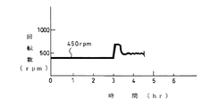
例えば、図4に示す如く、既に所定時間以上のアイドリング状態の継続が確認されて昇温制御がかかっていたとしても、PTOスイッチ16がオンの状態で外部アクセル17の特装用レバー19が操作されたことが制御装置9で検知されると、直ちに制御装置9内で昇温制御がキャンセルされて再生モードの燃料噴射信号10aが出力されなくなり、外部アクセル17の特装用レバー19で制御装置9に入力される補機15の手動操作が優先されることになる。
For example, as shown in FIG. 4, even if the continuation of the idling state for a predetermined time or more has already been confirmed and the temperature raising control has been applied, the
他方、補機15による作業を行わない通常のアイドリング状態、或いは、PTOスイッチ16がオンになっていても実質的な補機15への操作が実行されていないアイドリング状態が所定時間以上継続された場合には、制御装置9から再生モードの燃料噴射信号10a(昇温制御指令)が出力されるので、これを受けた燃料噴射装置10によりメイン噴射の一回当たりの噴射量が増加されて回転数が上げられ、これにより各気筒へのエネルギー投入量が増えて排気温度の上昇が図られ、しかも、アフタ噴射による燃料が出力に転換され難いタイミングで燃焼することでディーゼルエンジン1の熱効率が下がり、燃料の発熱量のうちの動力に利用されない熱量が増えて排気温度の上昇が図られることになる。
On the other hand, the normal idling state in which the operation by the
また、特に本形態例では、排気流量を絞り込むことが可能な排気絞り手段を成す排気ブレーキ20を排気昇温手段として併用しているので、前述したディーゼルエンジン1側における回転数の上昇とアフタ噴射の追加に合わせて排気ブレーキ20で排気流量が絞り込まれ、その上流側の排気ガス3が昇温されることで排気温度が上昇されると共に、排気抵抗が高まることにより気筒内に比較的温度の低い吸気が流入し難くなって比較的温度の高い排気ガス3の残留量が増加し、この比較的温度の高い排気ガス3を多く含む気筒内の空気が次の圧縮行程で圧縮されて爆発行程を迎えることでも更なる排気温度の上昇が図られることになる。
In particular, in the present embodiment, since the
そして、このようにしてパティキュレートフィルタ6の上流側で排気ガス3が昇温されると、結果的にパティキュレートフィルタ6の触媒床温度が高められて酸化触媒の活性化が図られることになり、アイドリング状態が長く継続して大量の炭化水素がパティキュレートフィルタ6に溜められてしまう前に炭化水素が酸化処理されて放出されることになる。
When the temperature of the
尚、このような白煙対策の昇温制御は、PTOスイッチ16がオンになっていても実質的な補機15への操作が実行されない限り実行されるので、闇雲にPTOスイッチ16がオンになった時点から昇温制御を阻止するよりも効率良くパティキュレートフィルタ6内の炭化水素を放出させることが可能となる。
Such temperature rise control for white smoke countermeasures is executed as long as the operation of the
従って、上記形態例によれば、エンジン動力をパワーテイクオフ装置14を介しアイドリング状態で取り出して補機15を操作している状況下で回転数の上昇やアフタ噴射の追加による昇温制御がかからないようにすることができるので、この昇温制御によりディーゼルエンジン1の運転状態が急変して補機15の作動不良を招くといった事態を確実に回避することができ、しかも、PTOスイッチ16がオンになっていても実質的な補機15への操作が実行されない限り昇温制御が極力実行されるようになっているので、補機15の作動不良を確実に回避しながらも白煙の発生確率を極力低下させることができる。
Therefore, according to the above embodiment, the engine temperature is taken out in the idling state via the power take-
尚、本発明の排気浄化装置の制御方法は、上述の形態例にのみ限定されるものではなく、排気昇温手段には図示する例以外の構成を採用しても良いこと、また、パティキュレートフィルタの前段には適宜にフロースルー型の酸化触媒を配置しても良いこと、排気絞り手段を排気ブレーキとは別に設けても良いこと、その他、本発明の要旨を逸脱しない範囲内において種々変更を加え得ることは勿論である。 Note that the control method of the exhaust gas purification apparatus of the present invention is not limited to the above-described embodiment example, and the exhaust gas temperature raising means may adopt a configuration other than the illustrated example, and the particulates. A flow-through type oxidation catalyst may be appropriately disposed in front of the filter, an exhaust throttle means may be provided separately from the exhaust brake, and various other modifications within the scope of the present invention. Of course, can be added.
1 ディーゼルエンジン(エンジン)
3 排気ガス
6 パティキュレートフィルタ
9 制御装置
10 燃料噴射装置(排気昇温手段)
10a 燃料噴射信号(昇温制御指令)
14 パワーテイクオフ装置
15 補機
16 PTOスイッチ(パワーテイクオフ装置のスイッチ)
16a オン信号
17 外部アクセル
18a 外部アクセル開度信号(操作入力)
19 特装用レバー
20 排気ブレーキ(排気絞り手段)
20a 開度指令信号(昇温制御指令)
1 Diesel engine (engine)
3
10a Fuel injection signal (temperature increase control command)
14 Power take-
16a ON
19
20a Opening command signal (temperature increase control command)
Claims (3)
Priority Applications (1)
| Application Number | Priority Date | Filing Date | Title |
|---|---|---|---|
| JP2003375229A JP4369727B2 (en) | 2003-11-05 | 2003-11-05 | Exhaust purification device control method |
Applications Claiming Priority (1)
| Application Number | Priority Date | Filing Date | Title |
|---|---|---|---|
| JP2003375229A JP4369727B2 (en) | 2003-11-05 | 2003-11-05 | Exhaust purification device control method |
Publications (2)
| Publication Number | Publication Date |
|---|---|
| JP2005139944A JP2005139944A (en) | 2005-06-02 |
| JP4369727B2 true JP4369727B2 (en) | 2009-11-25 |
Family
ID=34686654
Family Applications (1)
| Application Number | Title | Priority Date | Filing Date |
|---|---|---|---|
| JP2003375229A Expired - Lifetime JP4369727B2 (en) | 2003-11-05 | 2003-11-05 | Exhaust purification device control method |
Country Status (1)
| Country | Link |
|---|---|
| JP (1) | JP4369727B2 (en) |
Cited By (1)
| Publication number | Priority date | Publication date | Assignee | Title |
|---|---|---|---|---|
| US9759146B2 (en) | 2013-05-31 | 2017-09-12 | Kobelco Cranes Co., Ltd. | Exhaust gas purification control device for construction machine |
Families Citing this family (17)
| Publication number | Priority date | Publication date | Assignee | Title |
|---|---|---|---|---|
| JP4140640B2 (en) * | 2006-06-12 | 2008-08-27 | いすゞ自動車株式会社 | Exhaust gas purification method and exhaust gas purification system |
| JP4169076B2 (en) | 2007-01-25 | 2008-10-22 | いすゞ自動車株式会社 | Exhaust gas purification system control method and exhaust gas purification system |
| JP4100449B1 (en) * | 2007-01-26 | 2008-06-11 | いすゞ自動車株式会社 | Exhaust gas purification system control method and exhaust gas purification system |
| JP2009019534A (en) * | 2007-07-10 | 2009-01-29 | Tadano Ltd | Exhaust emission control device of working vehicle |
| JP5053015B2 (en) * | 2007-09-25 | 2012-10-17 | 日立建機株式会社 | Exhaust gas purification system for construction machinery |
| JP5122896B2 (en) * | 2007-09-25 | 2013-01-16 | 日立建機株式会社 | Exhaust gas purification system for construction machinery |
| KR101510491B1 (en) * | 2007-11-06 | 2015-04-08 | 히다찌 겐끼 가부시키가이샤 | Exhaust gas cleaning system for engineering vehicle |
| JP4878342B2 (en) * | 2007-12-10 | 2012-02-15 | 日立建機株式会社 | Exhaust gas purification system for work vehicles |
| JP5407288B2 (en) * | 2008-11-13 | 2014-02-05 | 三菱ふそうトラック・バス株式会社 | Exhaust gas treatment device and exhaust gas treatment method |
| US10371027B2 (en) | 2010-04-30 | 2019-08-06 | Yanmar Co., Ltd. | Exhaust gas purification system of working machine |
| JP5667782B2 (en) * | 2010-04-30 | 2015-02-12 | ヤンマー株式会社 | Exhaust gas purification system for work equipment |
| US9140157B2 (en) | 2010-05-07 | 2015-09-22 | Yanmar Co., Ltd. | Exhaust gas purification system |
| JP5828579B2 (en) | 2010-05-07 | 2015-12-09 | ヤンマー株式会社 | Exhaust gas purification system for work equipment |
| JP5839784B2 (en) | 2010-06-02 | 2016-01-06 | ヤンマー株式会社 | Exhaust gas purification system |
| JP6040078B2 (en) * | 2013-03-28 | 2016-12-07 | 日野自動車株式会社 | Exhaust purification device |
| WO2016043348A1 (en) * | 2015-10-09 | 2016-03-24 | 株式会社小松製作所 | Work vehicle and work vehicle control method |
| CN115992752A (en) * | 2023-01-18 | 2023-04-21 | 徐州重型机械有限公司 | DPF regeneration remote control system, control method and its crane |
-
2003
- 2003-11-05 JP JP2003375229A patent/JP4369727B2/en not_active Expired - Lifetime
Cited By (1)
| Publication number | Priority date | Publication date | Assignee | Title |
|---|---|---|---|---|
| US9759146B2 (en) | 2013-05-31 | 2017-09-12 | Kobelco Cranes Co., Ltd. | Exhaust gas purification control device for construction machine |
Also Published As
| Publication number | Publication date |
|---|---|
| JP2005139944A (en) | 2005-06-02 |
Similar Documents
| Publication | Publication Date | Title |
|---|---|---|
| JP4369727B2 (en) | Exhaust purification device control method | |
| JP4928335B2 (en) | Exhaust purification device | |
| JP4139259B2 (en) | Particulate filter regeneration method | |
| JP3938863B2 (en) | Exhaust purification device | |
| JP4012043B2 (en) | Particulate filter regeneration method | |
| JP2008223612A (en) | Exhaust purification device | |
| JP4327435B2 (en) | Exhaust purification equipment | |
| JP2004150417A (en) | Exhaust gas purification device | |
| JP4313160B2 (en) | Exhaust purification equipment | |
| JP2006037925A (en) | Exhaust emission control device of engine | |
| JP2005155444A (en) | Exhaust purification equipment | |
| JP2003286887A (en) | Exhaust white smoke prevention device | |
| JP4084289B2 (en) | Exhaust purification device | |
| JP2005155574A (en) | Exhaust purification equipment | |
| JP3914751B2 (en) | Exhaust purification method | |
| JP2005155532A (en) | Exhaust emission control device | |
| JP3922249B2 (en) | Engine exhaust purification system | |
| JP4377574B2 (en) | Exhaust purification equipment | |
| JP3971366B2 (en) | Exhaust purification device | |
| JP4163926B2 (en) | Exhaust white smoke prevention device | |
| JP3878833B2 (en) | Exhaust purification device | |
| JP5613477B2 (en) | Particulate filter regeneration device | |
| JP4293892B2 (en) | Exhaust purification equipment | |
| JP4293890B2 (en) | Exhaust purification equipment | |
| JP4276525B2 (en) | Exhaust purification equipment |
Legal Events
| Date | Code | Title | Description |
|---|---|---|---|
| A621 | Written request for application examination |
Free format text: JAPANESE INTERMEDIATE CODE: A621 Effective date: 20061026 |
|
| A131 | Notification of reasons for refusal |
Free format text: JAPANESE INTERMEDIATE CODE: A131 Effective date: 20081118 |
|
| A521 | Request for written amendment filed |
Free format text: JAPANESE INTERMEDIATE CODE: A523 Effective date: 20090109 |
|
| A131 | Notification of reasons for refusal |
Free format text: JAPANESE INTERMEDIATE CODE: A131 Effective date: 20090203 |
|
| TRDD | Decision of grant or rejection written | ||
| A01 | Written decision to grant a patent or to grant a registration (utility model) |
Free format text: JAPANESE INTERMEDIATE CODE: A01 Effective date: 20090825 |
|
| A01 | Written decision to grant a patent or to grant a registration (utility model) |
Free format text: JAPANESE INTERMEDIATE CODE: A01 |
|
| A61 | First payment of annual fees (during grant procedure) |
Free format text: JAPANESE INTERMEDIATE CODE: A61 Effective date: 20090828 |
|
| R150 | Certificate of patent or registration of utility model |
Ref document number: 4369727 Country of ref document: JP Free format text: JAPANESE INTERMEDIATE CODE: R150 Free format text: JAPANESE INTERMEDIATE CODE: R150 |
|
| FPAY | Renewal fee payment (event date is renewal date of database) |
Free format text: PAYMENT UNTIL: 20120904 Year of fee payment: 3 |
|
| FPAY | Renewal fee payment (event date is renewal date of database) |
Free format text: PAYMENT UNTIL: 20120904 Year of fee payment: 3 |
|
| FPAY | Renewal fee payment (event date is renewal date of database) |
Free format text: PAYMENT UNTIL: 20130904 Year of fee payment: 4 |
|
| R250 | Receipt of annual fees |
Free format text: JAPANESE INTERMEDIATE CODE: R250 |
|
| R250 | Receipt of annual fees |
Free format text: JAPANESE INTERMEDIATE CODE: R250 |
|
| R250 | Receipt of annual fees |
Free format text: JAPANESE INTERMEDIATE CODE: R250 |
|
| R250 | Receipt of annual fees |
Free format text: JAPANESE INTERMEDIATE CODE: R250 |
|
| EXPY | Cancellation because of completion of term |