JP4370077B2 - Container with cylindrical label - Google Patents
Container with cylindrical label Download PDFInfo
- Publication number
- JP4370077B2 JP4370077B2 JP2002141523A JP2002141523A JP4370077B2 JP 4370077 B2 JP4370077 B2 JP 4370077B2 JP 2002141523 A JP2002141523 A JP 2002141523A JP 2002141523 A JP2002141523 A JP 2002141523A JP 4370077 B2 JP4370077 B2 JP 4370077B2
- Authority
- JP
- Japan
- Prior art keywords
- cylindrical label
- container
- cylindrical
- container body
- protrusions
- Prior art date
- Legal status (The legal status is an assumption and is not a legal conclusion. Google has not performed a legal analysis and makes no representation as to the accuracy of the status listed.)
- Expired - Fee Related
Links
- 239000000853 adhesive Substances 0.000 claims description 26
- 230000001070 adhesive effect Effects 0.000 claims description 26
- 230000002093 peripheral effect Effects 0.000 claims description 20
- 239000012748 slip agent Substances 0.000 claims description 10
- 229920006257 Heat-shrinkable film Polymers 0.000 claims description 4
- 239000004033 plastic Substances 0.000 claims description 4
- 229920003023 plastic Polymers 0.000 claims description 4
- 229920000728 polyester Polymers 0.000 claims description 3
- XLYOFNOQVPJJNP-UHFFFAOYSA-N water Substances O XLYOFNOQVPJJNP-UHFFFAOYSA-N 0.000 claims description 3
- 235000014214 soft drink Nutrition 0.000 description 7
- BVKZGUZCCUSVTD-UHFFFAOYSA-N carbonic acid Chemical compound OC(O)=O BVKZGUZCCUSVTD-UHFFFAOYSA-N 0.000 description 5
- 229920000139 polyethylene terephthalate Polymers 0.000 description 5
- 239000005020 polyethylene terephthalate Substances 0.000 description 5
- -1 polyethylene terephthalate Polymers 0.000 description 4
- 229920006267 polyester film Polymers 0.000 description 3
- 244000269722 Thea sinensis Species 0.000 description 2
- 235000014171 carbonated beverage Nutrition 0.000 description 2
- 239000003795 chemical substances by application Substances 0.000 description 2
- 229920001225 polyester resin Polymers 0.000 description 2
- 239000004645 polyester resin Substances 0.000 description 2
- 230000002265 prevention Effects 0.000 description 2
- 229920005989 resin Polymers 0.000 description 2
- 239000011347 resin Substances 0.000 description 2
- 230000003068 static effect Effects 0.000 description 2
- 244000215068 Acacia senegal Species 0.000 description 1
- 229920001353 Dextrin Polymers 0.000 description 1
- 239000004375 Dextrin Substances 0.000 description 1
- 229920000084 Gum arabic Polymers 0.000 description 1
- 239000004743 Polypropylene Substances 0.000 description 1
- 239000004372 Polyvinyl alcohol Substances 0.000 description 1
- 235000010489 acacia gum Nutrition 0.000 description 1
- 239000000205 acacia gum Substances 0.000 description 1
- 238000000071 blow moulding Methods 0.000 description 1
- 239000005018 casein Substances 0.000 description 1
- BECPQYXYKAMYBN-UHFFFAOYSA-N casein, tech. Chemical compound NCCCCC(C(O)=O)N=C(O)C(CC(O)=O)N=C(O)C(CCC(O)=N)N=C(O)C(CC(C)C)N=C(O)C(CCC(O)=O)N=C(O)C(CC(O)=O)N=C(O)C(CCC(O)=O)N=C(O)C(C(C)O)N=C(O)C(CCC(O)=N)N=C(O)C(CCC(O)=N)N=C(O)C(CCC(O)=N)N=C(O)C(CCC(O)=O)N=C(O)C(CCC(O)=O)N=C(O)C(COP(O)(O)=O)N=C(O)C(CCC(O)=N)N=C(O)C(N)CC1=CC=CC=C1 BECPQYXYKAMYBN-UHFFFAOYSA-N 0.000 description 1
- 235000021240 caseins Nutrition 0.000 description 1
- 239000011248 coating agent Substances 0.000 description 1
- 230000008602 contraction Effects 0.000 description 1
- 235000019425 dextrin Nutrition 0.000 description 1
- 230000000694 effects Effects 0.000 description 1
- 150000002148 esters Chemical class 0.000 description 1
- 235000015203 fruit juice Nutrition 0.000 description 1
- 235000011389 fruit/vegetable juice Nutrition 0.000 description 1
- 238000010438 heat treatment Methods 0.000 description 1
- 239000000463 material Substances 0.000 description 1
- 239000000203 mixture Substances 0.000 description 1
- 229920002401 polyacrylamide Polymers 0.000 description 1
- 229920001155 polypropylene Polymers 0.000 description 1
- 229920005990 polystyrene resin Polymers 0.000 description 1
- 229920002451 polyvinyl alcohol Polymers 0.000 description 1
- 235000019422 polyvinyl alcohol Nutrition 0.000 description 1
- 239000004800 polyvinyl chloride Substances 0.000 description 1
- 229920000915 polyvinyl chloride Polymers 0.000 description 1
- 235000011496 sports drink Nutrition 0.000 description 1
- 230000009466 transformation Effects 0.000 description 1
Images


Landscapes
- Details Of Rigid Or Semi-Rigid Containers (AREA)
- Labeling Devices (AREA)
Description
【0001】
【発明の属する技術分野】
本発明は、例えばPETボトル等の容器本体に、熱収縮性を有する筒状ラベルを被嵌してなる筒状ラベル付き容器に関する。
【0002】
【従来の技術】
従来、お茶やジュース等の清涼飲料の容器として、内容物である清涼飲料等を充填するポリエチレンテレフタレート(PET)製ボトル等のプラスチック製の容器本体に、商品名やデザイン、内容物に関する説明等の表示が印刷された熱収縮性を有するフィルムからなる筒状ラベルを装着した筒状ラベル付き容器が公知である。
【0003】
この種の筒状ラベル付き容器に使用される容器本体の断面形状には、大きく分けて円形状と角形状の二種類がある。詳しく説明すると、炭酸が含まれた清涼飲料を容器本体に充填した場合、容器本体には炭酸によって内圧が作用する。そこで、このような炭酸飲料が充填される容器本体には円形状断面のものが使用される。また、果汁入り飲料、スポーツドリンク、お茶やコーヒーなど炭酸が含まれない清涼飲料を充填する容器本体は、容器強度、変形防止、デザイン性等の点から四角形状や六角形状などの角形状断面(部分的に円形状断面を有するものも多い)のものが主として使用されている。該角形状断面の容器本体は、頂点として外側に向かって凸状に突出した突出部を外周面に備え、少なくとも突出部が筒状ラベルと接触することで筒状ラベルが容器本体の外周面に被嵌されている。
【0004】
いずれの形状であっても、この筒状ラベル付き容器は、軽量性、耐衝撃性、内容物保存性などの優れた特性を備え、さらにその手軽さから広く使用されており、店頭販売だけでなく自動販売機などでも販売されるようになってきている。
【0005】
【発明が解決しようとする課題】
ところで、近年、省資源化が進むなか、筒状ラベル付き容器においても、容器本体に使用される材料を削減するために、当該容器本体の厚さを薄くすることが求められている。
【0006】
しかしながら、容器本体の厚さを薄くすると容器本体の剛性が低下し、その結果、容器本体が変形して潰れ易くなってしまう。特に、角形状断面の容器本体は、変形し易くなる。即ち、炭酸飲料が充填された円形状断面の容器本体では、上述の如く、炭酸によって容器本体内に内圧が生じているため、容器本体の厚さを薄くしても潰れ難い。その一方、角形状断面の容器本体である場合、充填される清涼飲料には炭酸が含まれていないため、容器本体の厚さを薄くすると外力によって容器本体が変形して潰れ易くなるという問題がある。
【0007】
例えば、自動販売機などに筒状ラベル付き容器を充填した際、下方に位置する筒状ラベル付き容器が、その上に積まれた他の筒状ラベル付き容器の重量によって変形して潰れると、筒状ラベル付き容器が販売機内で詰まってしまうなどのトラブルが発生する場合がある。
【0008】
そこで、本発明はこのような問題を解決するためになされたもので、容器本体の厚みを薄くしても容器本体の変形を防止可能な筒状ラベル付き容器を提供することを課題とする。
【0009】
【課題を解決するための手段】
上記課題を解決するために、本発明に係るラベル付き容器は、熱収縮性フィルムからなる筒状ラベルが、プラスチック製のボトル状の容器本体の外周面に被嵌された筒状ラベル付き容器であって、容器本体は、周方向に間隔をおいて設けられ、筒状ラベルと接触するように外側に向かって凸状に屈曲して形成された複数の突出部と、各突出部の間に設けられ、平面状又は内側に向かって凹状に屈曲して形成されたパネル壁部とをその外周面に備え、隣り合う突出部同士の距離変化を防止するように、筒状ラベルの内周面のうち少なくとも突出部と接触している領域には滑り防止剤として感熱性接着剤又は感湿性接着剤が設けられていると共に、筒状ラベルはポリエステル製でその周方向の延伸倍率が3.5〜6倍で且つ熱収縮率が80℃の温水10秒で55%以上のものであって突出部間において直線状となるように収縮していることを特徴とする。尚、本発明において滑り防止剤とは、容器本体に外力が作用した際に筒状ラベルと突出部との接触箇所が位置ずれを起こさないないように固定するものである。
【0010】
通常、容器本体が外力を受けて変形するとき、突出部の位置が移動する。具体的には、容器本体の変形によって、ある部分では隣り合う突出部同士が相対的に近づき、また他の部分では隣り合う突出部同士が相対的に離れる。従来、筒状ラベルと突出部とは接触しているだけであったため、筒状ラベルと容器本体とは別個に変形していた。しかし、請求項1に記載の筒状ラベル付き容器によれば、各突出部と筒状ラベルとが滑り防止剤によって固定されているため、容器本体の変形に伴い隣り合う突出部同士が相対的に離れることがラベルによって防止される。その結果、隣り合う突出部同士が相対的に近づくことも抑制されるため、全体として容器本体の変形を防止することができる。尚、容器本体が突出部以外の位置でも筒状ラベルと接触している形状である場合、突出部に加えてその接触している位置で容器本体と筒状ラベルとが滑り防止剤によって固定されていてもよい。
【0011】
前記滑り防止剤として、感熱性接着剤又は水分を加えることにより粘着性が生じる感湿性接着剤を用いることが好ましい。
【0012】
容器本体に筒状ラベルを被嵌するときは、例えば、容器本体に筒状ラベルを被せた後、該筒状ラベルにスチームを当てることにより筒状ラベルを収縮させて容器本体に被嵌する。この時、スチームの水分によって、筒状ラベルの内周面に設けられた感湿性接着剤に粘着性が発生し、筒状ラベルと突出部とが固定される。また、筒状ラベルに熱を加えることにより、筒状ラベルが収縮すると共に、感熱性接着剤に粘着性が発生し、筒状ラベルと突出部とが固定される。
【0015】
【発明の実施の形態】
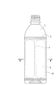
以下、本発明の実施の形態を添付図面を参照して説明する。図1は、本実施形態にかかる筒状ラベル付き容器の側面図であり、図2(イ)は図1におけるA−A線断面図、図2(ロ)は図2(イ)の部分拡大図を示す。本実施形態にかかる筒状ラベル付き容器は、図1及び図2に示す如く、ボトル状の容器本体1と、該容器本体1の外周面に被嵌される筒状ラベル2とを備えている。
【0016】
容器本体1は、筒状の胴部10を有し、前記筒状ラベル2は該胴部10の外周面に被嵌されている。胴部10の上端には内容物である清涼飲料などを出し入れするための開口部が設けられている。該開口部は蓋体(図示省略)が着脱可能に構成され、清涼飲料を容器本体内に充填した後に蓋体を螺着することで開口部を閉塞して容器本体1内を密封状態にすることができる。かかる容器本体1は、プラスチック製であり、好ましくはポリエチレンテレフタレート等のポリエステル系樹脂をブロー成形(PETボトル)することで形成される。
【0017】
前記胴部10は、図2(イ)に示す如く、断面が略多角形状をなしている。詳細に説明すると、胴部10は、周方向に所定間隔を隔てて設けられた複数の突出部4,…と、各突出部4,…の間に設けられたパネル壁部5,…とからなり、突出部4,…を頂点とした多角形状(本実施形態においては、突出部4,…が6つ設けられた六角形状)をなしている。
【0018】
前記突出部4,…は、径方向外側に向けて凸状に突出しており、周方向に等間隔をなして設けられている。筒状ラベル2は、該突出部4,…と接触することで胴部10に被嵌されている。そして前記パネル壁部5,…は、径方向内側に向けて凹状に湾曲した円弧状に形成されている。即ち、後述するように、筒状ラベル2を熱収縮させて胴部10に被嵌したときに、筒状ラベル2とパネル壁部5,…とが非接触になるように構成されている。好ましくは、周方向において、突出部4,…の長さは、パネル壁部5,…の長さよりも短く設ける。
【0019】
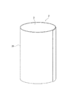
筒状ラベル2は、図3に示す如く、熱収縮性を有する矩形状のフィルム20の両端部を接着することにより筒状に形成されている。フィルム20は、厚さ10〜80μm(好ましくは20〜50μm)のポリエステル系樹脂、ポリスチレン系樹脂、ポリプロピレン系樹脂、或いは、ポリ塩化ビニル系樹脂などからなり、主に一軸方向に延伸して形成され、該主延伸方向を周方向として筒状に形成したときにその周方向に熱収縮性を有している。従って、筒状ラベル2を容器本体1の胴部10に外周に位置させた状態で加熱することにより該筒状ラベル2が周方向に収縮するため胴部10の外周面に被嵌することができる。
【0020】
また、筒状ラベル2の内周面には、全面にわたって滑り防止剤3が塗布されている。従って、筒状ラベル2を胴部10に被嵌したときに、突出部4,…において筒状ラベル2と胴部10とが固定される。滑り防止剤3は、ポリエステル製フィルムとの摩擦係数が、0.7以上(ポリエステル製フィルム表面同士の静摩擦係数が0.45であるポリエステル製フィルム(例えば、東洋紡エステルフィルムE5000:東洋紡(株))の表面に対して測定した静摩擦係数。尚、摩擦係数はJIS−K−7125に基づき測定)程度のものを使用することができ、例えば、前記摩擦係数となる印刷インキやコーティング剤、好ましくは接着剤を使用することができる。具体的には、本実施形態においては滑り防止剤3としてカゼイン、デキストリン、ポリビニルアルコール、アラビアゴム、ポリアクリルアミドなどやこれらの変性物、混合物などの感湿性(再湿性)接着剤3が採用されている。特に、接着剤を用いている場合は、弱い粘着力で擬似的に接着しているだけで十分である。
【0021】
容器本体1に筒状ラベル2を被嵌するには、まず容器本体1の胴部10を覆うように筒状ラベル2を配置した状態で、当該筒状ラベル2にスチームを当てると、筒状ラベル2が周方向に収縮して、突出部4,…と筒状ラベル2とが接触する。そして、さらにスチームを当て、各突出部4,…間で直線状になるまで筒状ラベル2を収縮させる。この時、パネル壁部5,…は、内側に凹状に設けられているため、筒状ラベル2とパネル壁部5,…とは非接触状態となる。また、筒状ラベル2が収縮すると同時に、スチームの水分によって筒状ラベル2の内周面に塗布された感湿性接着剤3に粘着性が生じることにより、筒状ラベル2と突出部4,…とが接着する。その後、感湿性接着剤3が乾燥すると突出部4,…と筒状ラベル2とが完全に固定される。
【0022】
本実施形態に係る筒状ラベル付き容器は、上述の如く構成され、筒状ラベル2の内周面に感湿性接着剤3を塗布して筒状ラベル2と突出部4,…とを固定することにより、容器本体1の変形を防止することができる。即ち、従来の筒状ラベル付き容器においては、図5に示す如く、外力が作用するとパネル壁部5,…が変形する。ここで図5において、容器本体1は前記実施形態に係る筒状ラベル付き容器と同形状とし、同一の構成に付いては同一符号を付してその詳細な説明は省略する。パネル壁部5,…が変形すると、容器本体1と筒状ラベル2とは接触しているだけであるため、突出部4,…と筒状ラベル2とが互いに滑って、ある部分で隣り合う突出部4a,4bが相対的に離れ、また、他の部分で隣り合う突出部4b,4cが相対的に近づく。一方、本実施形態に係る筒状ラベル付き容器にあっては、突出部4,…と筒状ラベル2が固定されているため、ある部分で隣り合う突出部4a,4bが相対的に離れることを筒状ラベル2により防止することができる。そうすると、他の部分で隣り合う突出部4b,4cが相対的に近づくことも防止され、その結果、容器本体1の変形を防止することができる。特に、本発明の筒状ラベル2は、前記の如く主に周方向に延伸されたフィルムを用いているため、周方向に伸び難く変形防止性に優れている。特に主延伸方向の延伸倍率が3.5〜6倍程度のポリエステル製熱収縮フィルムからなる筒状ラベル2は、周方向の収縮力が強く、伸び難いため好ましい。この筒状ラベル2の熱収縮率としては、容器本体1は薄くても、装着(収縮)時にダメージを与え難いように80℃(温水10秒)で55%以上のものが好ましい。
【0023】
従来の筒状ラベル付き容器にあっては、容器本体の厚みを厚くして当該容器本体の変形を防止する必要があった。一方、本実施形態に係る筒状ラベル付き容器にあっては、容器本体1の厚さを従来の筒状ラベル付き容器よりも薄くすることができる。
【0024】
また、筒状ラベル2の内周面に塗布されている感湿性接着剤3は、水分に反応して粘着性が生じるため、筒状ラベル2にスチームなどの水分を加えるまでは粘着性が生じていないため、筒状ラベル2の取り扱いが容易となる。
【0025】
さらに、感湿性接着剤3は、筒状ラベル2がスチームの熱により収縮して突出部4,…と接触した後に、乾燥して徐々に固まるため、熱収縮後に筒状ラベル2の位置が多少ずれていても、修正することができる。
【0026】
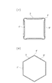
尚、本発明のラベル付きボトルは、上記した実施の形態に限定されるものではなく、本発明の要旨を逸脱しない範囲内において種々変更を加え得ることは勿論である。例えば、本実施形態において、パネル壁部5,…は内側に凹状に設けられているが、図4(ロ)に示す如く、各突出部4’’,…を正多角形の頂部によって形成させるようにしてもよい。即ち、容器本体1’’が、いわゆる正多角形(図4(ロ)においては、突出部5’’,…が6つ設けられた正六角形)をなすようにパネル壁部5’’,…が平板状に形成されたものである。この場合、容器本体1’’と筒状ラベル2とが、全周にわたって接触するが、筒状ラベル2を熱収縮したときに、突出部4’’,…と筒状ラベル2とがしっかりと接触して固定されることにより、容器本体1’’の変形を防止することができる。さらに、筒状ラベル2の内周面全体に感湿性接着剤3が塗布されていると、パネル壁部5’,…でも筒状ラベル2が固定されるため、容器本体1’’がより変形し難くなる。
【0027】
また、図4(イ)に示す如く、容器本体1’は、突出部4’…が4つ設けられた略四角形状であってもよい。かかる容器本体1’においても筒状ラベル2は、突出部4,…において固定されているため、パネル壁部5,…が変形して隣り合う突出部5,…同士が相対的に離れようとすることを筒状ラベル2によって防止することができる。即ち、容器本体1’は、複数の突出部を備えると共に、該突出部において筒状ラベル2と固定されていればよく、突出部の数は本実施形態に限定されるものではない。
【0028】
胴部10(図1)は断面形状が一様である必要はなく、例えば、部分的にその断面が円形状であってもよい。
【0029】
感湿性接着剤3は、筒状ラベルの内周面全体に塗布されているが、少なくとも胴部10と接触する領域、即ち、突出部5,…に対応する領域に設けられていればよい。
【0030】
また、本実施形態において、筒状ラベル2の内周面には感湿性接着剤が塗布されているが、感熱性接着剤であってもよい。この場合、筒状ラベル2に熱を加えることにより、筒状ラベル2が収縮すると共に、感熱性接着剤に粘着性が発生するため、筒状ラベル2と容器本体1とを固定することができる。尚、接着剤による固定は、弱い粘着力で擬似的に接着している程度で十分である。
【0031】
【発明の効果】
以上のように、本発明に係る筒状ラベル付き容器は、容器本体の突出部と該突出部と接触している筒状ラベルの領域の相対位置を固定すべく、筒状ラベルの内周面に滑り防止剤を設けると共に、筒状ラベルとして周方向の延伸倍率が3.5〜6倍で且つ熱収縮率が80℃の温水10秒で55%以上であるポリエステル製のものを使用して突出部間において直線状となるように収縮させていることにより、隣り合う突出部同士の距離が相対的に変化することが防止されるため、容器本体の厚さを薄くしても当該容器本体の変形を防止できる。
【図面の簡単な説明】
【図1】本発明の実施形態に係る筒状ラベル付き容器を示す正面図。
【図2】(イ)は、図1におけるA−A線断面図であり、(ロ)は(イ)の部分拡大図を示す。
【図3】同実施形態における筒状ラベルを示す斜視図。
【図4】(イ)及び(ロ)は、容器本体の他の形態を示す断面図。
【図5】従来の筒状ラベル付き容器の断面図であり、外力が作用して変形した状態を示す。
【符号の説明】
1…容器本体、2…筒状ラベル、3…感湿性接着剤(滑り防止剤)、4,4a,4b,4c…突出部、5,5a,5b,5c…パネル壁部、10…胴部、20…フィルム[0001]
BACKGROUND OF THE INVENTION
The present invention is, for example, the container body such as a PET bottle, relates a cylindrical label having a heat shrinkability in the cylindrical labeled container formed by fitting the.
[0002]
[Prior art]
Conventionally, as a container for soft drinks such as tea and juice, the product name, design, description of contents, etc. on plastic container bodies such as polyethylene terephthalate (PET) bottles that are filled with soft drinks as contents A container with a cylindrical label equipped with a cylindrical label made of a heat-shrinkable film printed with a display is known.
[0003]
The cross-sectional shape of the container body used in this type of container with a cylindrical label is roughly divided into two types, a circular shape and a square shape. More specifically, when a soft drink containing carbonic acid is filled in a container main body, an internal pressure acts on the container main body due to carbonic acid. Therefore, a container having a circular cross section is used as a container body filled with such a carbonated beverage. In addition, the container body filled with soft drinks that do not contain carbonic acid, such as fruit juice drinks, sports drinks, tea and coffee, has a rectangular cross section (such as a square or hexagonal shape) in terms of container strength, deformation prevention, and design. Most of them have a partially circular cross section). The container body having the square cross section has a protruding portion that protrudes outward as a vertex on the outer peripheral surface, and at least the protruding portion comes into contact with the cylindrical label so that the cylindrical label is placed on the outer peripheral surface of the container main body. It is fitted.
[0004]
Regardless of the shape, this cylindrically labeled container has excellent characteristics such as lightness, impact resistance, and storage stability, and is widely used for its ease of use. There are also vending machines sold.
[0005]
[Problems to be solved by the invention]
By the way, in recent years, with the progress of resource saving, in a container with a cylindrical label, it is required to reduce the thickness of the container body in order to reduce the material used for the container body.
[0006]
However, if the thickness of the container main body is reduced, the rigidity of the container main body is lowered, and as a result, the container main body is deformed and easily crushed. In particular, the container body having a square cross section is easily deformed. That is, in a circular cross-section container body filled with a carbonated beverage, as described above, internal pressure is generated in the container body due to carbonic acid, and therefore it is difficult to be crushed even if the thickness of the container body is reduced. On the other hand, when the container body has a square cross section, since the soft drink to be filled does not contain carbonic acid, there is a problem that when the thickness of the container body is reduced, the container body is easily deformed and crushed by an external force. is there.
[0007]
For example, when filling a container with a cylindrical label in a vending machine or the like, if the container with a cylindrical label positioned below is deformed and crushed by the weight of the other container with a cylindrical label stacked thereon, Troubles such as the container with the cylindrical label being clogged in the vending machine may occur.
[0008]
The present invention has been made in order to solve such a problem, it is an object of the invention to provide a preventable tubular labeled container deformation of the container body even if the thickness of the container body .
[0009]
[Means for Solving the Problems]
In order to solve the above-mentioned problems, a container with a label according to the present invention is a container with a cylindrical label in which a cylindrical label made of a heat-shrinkable film is fitted on the outer peripheral surface of a plastic bottle-shaped container body. The container body is provided between the plurality of projecting portions provided at intervals in the circumferential direction and bent in a convex manner toward the outside so as to come into contact with the cylindrical label. An inner peripheral surface of the cylindrical label so as to prevent a change in the distance between adjacent projecting portions provided on the outer peripheral surface of the panel wall portion that is provided and is formed in a planar shape or bent in a concave shape toward the inside. At least the region in contact with the protrusion is provided with a heat-sensitive adhesive or moisture-sensitive adhesive as an anti-slip agent, and the cylindrical label is made of polyester and has a stretching ratio of 3.5 in the circumferential direction. and thermal shrinkage of 80 ° C. temperature with 6-fold Characterized in that it shrinks to be a straight line between the protruding portions be not less than 55% in 10 seconds. In the present invention, the anti-slip agent is used to fix the contact portion between the cylindrical label and the protruding portion so as not to be displaced when an external force is applied to the container body.
[0010]
Usually, when a container main body receives external force and deform | transforms, the position of a protrusion part moves. Specifically, due to the deformation of the container body, adjacent protrusions are relatively close to each other, and adjacent protrusions are relatively separated from each other. Conventionally, since the cylindrical label and the protrusion are only in contact with each other, the cylindrical label and the container main body are separately deformed. However, according to the container with a cylindrical label according to
[0011]
As the anti-slip agent, it is preferable to use a heat-sensitive adhesive or a moisture-sensitive adhesive that generates tackiness by adding moisture.
[0012]
When the cylindrical label is fitted on the container main body, for example, after the cylindrical label is put on the container main body, the cylindrical label is contracted by applying steam to the cylindrical label to fit the container main body. At this time, the moisture of the steam causes stickiness to the moisture sensitive adhesive provided on the inner peripheral surface of the cylindrical label, and the cylindrical label and the protruding portion are fixed. In addition, by applying heat to the cylindrical label, the cylindrical label contracts, and the heat-sensitive adhesive becomes sticky, and the cylindrical label and the protruding portion are fixed.
[0015]
DETAILED DESCRIPTION OF THE INVENTION
Embodiments of the present invention will be described below with reference to the accompanying drawings. 1 is a side view of a container with a cylindrical label according to the present embodiment, FIG. 2 (a) is a cross-sectional view taken along line AA in FIG. 1, and FIG. 2 (b) is a partially enlarged view of FIG. The figure is shown. As shown in FIGS. 1 and 2, the container with a cylindrical label according to the present embodiment includes a bottle-shaped container
[0016]
The
[0017]
The
[0018]
The projecting
[0019]
As shown in FIG. 3, the
[0020]
An
[0021]
In order to fit the
[0022]
The container with a cylindrical label according to the present embodiment is configured as described above, and applies the moisture-
[0023]
In a conventional container with a cylindrical label, it is necessary to increase the thickness of the container body to prevent the deformation of the container body. On the other hand, in the container with a cylindrical label according to the present embodiment, the thickness of the
[0024]
Moreover, since the moisture-
[0025]
Further, the moisture-
[0026]
In addition, the bottle with a label of the present invention is not limited to the above-described embodiment, and it is needless to say that various changes can be made without departing from the gist of the present invention. For example, in the present embodiment, the
[0027]
As shown in FIG. 4 (a), the
[0028]
The trunk portion 10 (FIG. 1) does not need to have a uniform cross-sectional shape. For example, the cross-sectional shape may be partially circular.
[0029]
Although the moisture-
[0030]
Moreover, in this embodiment, although the moisture sensitive adhesive is apply | coated to the internal peripheral surface of the
[0031]
【The invention's effect】
As described above, the container with a cylindrical label according to the present invention has an inner peripheral surface of the cylindrical label so as to fix the relative position of the protruding portion of the container main body and the region of the cylindrical label in contact with the protruding portion. An anti-slip agent is provided on the sleeve, and a cylindrical label having a stretch ratio of 3.5 to 6 times in the circumferential direction and a thermal shrinkage rate of 55% or more in 10 seconds of hot water at 80 ° C. is used. Since the distance between adjacent protrusions is prevented from relatively changing by contracting the protrusions so as to be linear, the container body can be reduced even if the thickness of the container body is reduced. Can be prevented from being deformed.
[Brief description of the drawings]
FIG. 1 is a front view showing a container with a cylindrical label according to an embodiment of the present invention.
2A is a cross-sectional view taken along line AA in FIG. 1, and FIG. 2B is a partially enlarged view of FIG.
FIG. 3 is a perspective view showing a cylindrical label in the embodiment.
4A and 4B are cross-sectional views showing other forms of the container body.
FIG. 5 is a cross-sectional view of a conventional container with a cylindrical label, and shows a deformed state due to an external force.
[Explanation of symbols]
DESCRIPTION OF
Claims (1)
Priority Applications (1)
| Application Number | Priority Date | Filing Date | Title |
|---|---|---|---|
| JP2002141523A JP4370077B2 (en) | 2002-05-16 | 2002-05-16 | Container with cylindrical label |
Applications Claiming Priority (1)
| Application Number | Priority Date | Filing Date | Title |
|---|---|---|---|
| JP2002141523A JP4370077B2 (en) | 2002-05-16 | 2002-05-16 | Container with cylindrical label |
Publications (3)
| Publication Number | Publication Date |
|---|---|
| JP2003335343A JP2003335343A (en) | 2003-11-25 |
| JP2003335343A5 JP2003335343A5 (en) | 2005-10-06 |
| JP4370077B2 true JP4370077B2 (en) | 2009-11-25 |
Family
ID=29702080
Family Applications (1)
| Application Number | Title | Priority Date | Filing Date |
|---|---|---|---|
| JP2002141523A Expired - Fee Related JP4370077B2 (en) | 2002-05-16 | 2002-05-16 | Container with cylindrical label |
Country Status (1)
| Country | Link |
|---|---|
| JP (1) | JP4370077B2 (en) |
Families Citing this family (16)
| Publication number | Priority date | Publication date | Assignee | Title |
|---|---|---|---|---|
| JP5059893B2 (en) * | 2002-11-29 | 2012-10-31 | 株式会社吉野工業所 | Plastic container |
| JP4641716B2 (en) * | 2002-11-29 | 2011-03-02 | 株式会社吉野工業所 | Plastic container |
| AU2004293256A1 (en) * | 2003-11-26 | 2005-06-09 | Yoshino Kogyosho Co., Ltd. | Synthetic Resin Container |
| JP2005193984A (en) * | 2003-12-10 | 2005-07-21 | Fuji Seal International Inc | Container with tubular label and heat shrink type tubular label |
| JP4679126B2 (en) * | 2003-12-10 | 2011-04-27 | 株式会社フジシールインターナショナル | Container with cylindrical label |
| US7851049B2 (en) | 2004-03-08 | 2010-12-14 | Fuji Seal International, Inc. | Heat-shrinkable cylindrical label |
| JPWO2005092721A1 (en) * | 2004-03-26 | 2008-02-07 | 株式会社フジシールインターナショナル | Bottle with label |
| JP4708007B2 (en) * | 2004-12-02 | 2011-06-22 | 株式会社フジシールインターナショナル | Shrink labels and labeled containers |
| JP4778709B2 (en) * | 2005-01-13 | 2011-09-21 | 東洋紡績株式会社 | Heat insulating material, and anti-condensation cold insulation container and heat insulating container provided with the same |
| JP4540110B2 (en) * | 2005-04-19 | 2010-09-08 | 株式会社フジシールインターナショナル | Heat-shrinkable cylindrical label |
| MX2009010792A (en) | 2007-04-05 | 2009-12-14 | Avery Dennison Corp | Pressure sensitive shrink label. |
| US8282754B2 (en) | 2007-04-05 | 2012-10-09 | Avery Dennison Corporation | Pressure sensitive shrink label |
| BR112012001932A2 (en) * | 2009-07-27 | 2016-03-15 | Avery Dennison Corp | systems and processes for applying shrink labels |
| US9221573B2 (en) | 2010-01-28 | 2015-12-29 | Avery Dennison Corporation | Label applicator belt system |
| DE102012013590A1 (en) * | 2012-07-10 | 2014-01-16 | Sanner Gmbh | container |
| CN111959909B (en) * | 2020-08-31 | 2022-04-01 | 河北国润药品包装材料股份有限公司 | Medicine box labeling machine for pharmaceutical factory |
-
2002
- 2002-05-16 JP JP2002141523A patent/JP4370077B2/en not_active Expired - Fee Related
Also Published As
| Publication number | Publication date |
|---|---|
| JP2003335343A (en) | 2003-11-25 |
Similar Documents
| Publication | Publication Date | Title |
|---|---|---|
| JP4370077B2 (en) | Container with cylindrical label | |
| US20080017605A1 (en) | Polygonal hot-fill container, package and method of making | |
| JPH06505949A (en) | Plastic container packaging with paperboard jacket | |
| JPS5828161B2 (en) | Method of forming sealed containers | |
| US8136694B1 (en) | Cup with improved characteristics | |
| CA3120714A1 (en) | Dual-seal liner and non-removable closure assembly | |
| US20070051691A1 (en) | Cap with visible tamper-indicating seal | |
| JP2001294282A (en) | Labeled container | |
| JP4969321B2 (en) | Heat-shrinkable cylindrical label | |
| JPH10338277A (en) | Outer body of microwave cooking container | |
| US20080035636A1 (en) | Multiple-container packages | |
| JP5090850B2 (en) | Heat-shrinkable cylindrical label and container with cylindrical label | |
| JP4601139B2 (en) | Cylindrical label and labeled container | |
| JP2006213341A (en) | Heat-shrinkable cylindrical label | |
| JP4526641B2 (en) | Blister case for contact lenses | |
| JP3992350B2 (en) | Label forming substrate | |
| JP2503504Y2 (en) | Stretch labels for PET bottles and PET bottles with stretch labels | |
| JP2007216984A (en) | Manufacturing method for labelled container and labelled container | |
| JP2008120398A (en) | Cuplike container body and packaging method | |
| JP7814109B2 (en) | label | |
| WO2023013291A1 (en) | Labeled container for food or drink and method for producing same | |
| JP2004157189A (en) | Container adhesion label and container | |
| JP4441037B2 (en) | Cap seals and containers with cap seals | |
| JP4054205B2 (en) | Sealed packaging method and sealed package | |
| JPH11327277A (en) | Labeled toner container or developer container and label mounting method |
Legal Events
| Date | Code | Title | Description |
|---|---|---|---|
| A521 | Written amendment |
Free format text: JAPANESE INTERMEDIATE CODE: A523 Effective date: 20050513 |
|
| A621 | Written request for application examination |
Free format text: JAPANESE INTERMEDIATE CODE: A621 Effective date: 20050513 |
|
| A977 | Report on retrieval |
Free format text: JAPANESE INTERMEDIATE CODE: A971007 Effective date: 20070517 |
|
| A131 | Notification of reasons for refusal |
Free format text: JAPANESE INTERMEDIATE CODE: A131 Effective date: 20070601 |
|
| A521 | Written amendment |
Free format text: JAPANESE INTERMEDIATE CODE: A523 Effective date: 20070724 |
|
| A02 | Decision of refusal |
Free format text: JAPANESE INTERMEDIATE CODE: A02 Effective date: 20071116 |
|
| A521 | Written amendment |
Free format text: JAPANESE INTERMEDIATE CODE: A523 Effective date: 20080115 |
|
| A911 | Transfer of reconsideration by examiner before appeal (zenchi) |
Free format text: JAPANESE INTERMEDIATE CODE: A911 Effective date: 20080215 |
|
| A912 | Removal of reconsideration by examiner before appeal (zenchi) |
Free format text: JAPANESE INTERMEDIATE CODE: A912 Effective date: 20080314 |
|
| RD04 | Notification of resignation of power of attorney |
Free format text: JAPANESE INTERMEDIATE CODE: A7424 Effective date: 20080618 |
|
| A01 | Written decision to grant a patent or to grant a registration (utility model) |
Free format text: JAPANESE INTERMEDIATE CODE: A01 |
|
| A61 | First payment of annual fees (during grant procedure) |
Free format text: JAPANESE INTERMEDIATE CODE: A61 Effective date: 20090831 |
|
| R150 | Certificate of patent or registration of utility model |
Free format text: JAPANESE INTERMEDIATE CODE: R150 |
|
| FPAY | Renewal fee payment (event date is renewal date of database) |
Free format text: PAYMENT UNTIL: 20120904 Year of fee payment: 3 |
|
| FPAY | Renewal fee payment (event date is renewal date of database) |
Free format text: PAYMENT UNTIL: 20120904 Year of fee payment: 3 |
|
| S531 | Written request for registration of change of domicile |
Free format text: JAPANESE INTERMEDIATE CODE: R313531 |
|
| FPAY | Renewal fee payment (event date is renewal date of database) |
Free format text: PAYMENT UNTIL: 20120904 Year of fee payment: 3 |
|
| R350 | Written notification of registration of transfer |
Free format text: JAPANESE INTERMEDIATE CODE: R350 |
|
| FPAY | Renewal fee payment (event date is renewal date of database) |
Free format text: PAYMENT UNTIL: 20120904 Year of fee payment: 3 |
|
| FPAY | Renewal fee payment (event date is renewal date of database) |
Free format text: PAYMENT UNTIL: 20120904 Year of fee payment: 3 |
|
| FPAY | Renewal fee payment (event date is renewal date of database) |
Free format text: PAYMENT UNTIL: 20130904 Year of fee payment: 4 |
|
| R250 | Receipt of annual fees |
Free format text: JAPANESE INTERMEDIATE CODE: R250 |
|
| R250 | Receipt of annual fees |
Free format text: JAPANESE INTERMEDIATE CODE: R250 |
|
| R250 | Receipt of annual fees |
Free format text: JAPANESE INTERMEDIATE CODE: R250 |
|
| R250 | Receipt of annual fees |
Free format text: JAPANESE INTERMEDIATE CODE: R250 |
|
| R250 | Receipt of annual fees |
Free format text: JAPANESE INTERMEDIATE CODE: R250 |
|
| LAPS | Cancellation because of no payment of annual fees |