JP4375889B2 - Premolar tube - Google Patents
Premolar tube Download PDFInfo
- Publication number
- JP4375889B2 JP4375889B2 JP2000259513A JP2000259513A JP4375889B2 JP 4375889 B2 JP4375889 B2 JP 4375889B2 JP 2000259513 A JP2000259513 A JP 2000259513A JP 2000259513 A JP2000259513 A JP 2000259513A JP 4375889 B2 JP4375889 B2 JP 4375889B2
- Authority
- JP
- Japan
- Prior art keywords
- tube
- base
- hole
- premolar
- archwire
- Prior art date
- Legal status (The legal status is an assumption and is not a legal conclusion. Google has not performed a legal analysis and makes no representation as to the accuracy of the status listed.)
- Expired - Lifetime
Links
- 210000004763 bicuspid Anatomy 0.000 claims description 24
- 238000011282 treatment Methods 0.000 claims description 15
- 238000011221 initial treatment Methods 0.000 claims description 9
- 238000003780 insertion Methods 0.000 claims description 9
- 230000037431 insertion Effects 0.000 claims description 9
- 238000000034 method Methods 0.000 claims description 7
- 239000000853 adhesive Substances 0.000 description 5
- 230000001070 adhesive effect Effects 0.000 description 5
- 230000003068 static effect Effects 0.000 description 5
- 230000001680 brushing effect Effects 0.000 description 3
- 210000004513 dentition Anatomy 0.000 description 3
- 230000036346 tooth eruption Effects 0.000 description 3
- 230000001055 chewing effect Effects 0.000 description 2
- 238000004140 cleaning Methods 0.000 description 2
- 238000012937 correction Methods 0.000 description 2
- 238000011161 development Methods 0.000 description 2
- 230000018109 developmental process Effects 0.000 description 2
- 230000000149 penetrating effect Effects 0.000 description 2
- 238000007796 conventional method Methods 0.000 description 1
- 208000002925 dental caries Diseases 0.000 description 1
- 230000000694 effects Effects 0.000 description 1
- 201000001245 periodontitis Diseases 0.000 description 1
- 238000012546 transfer Methods 0.000 description 1
Images


Landscapes
- Dental Tools And Instruments Or Auxiliary Dental Instruments (AREA)
Description
【0001】
【発明の属する技術分野】
本発明は、歯科用の歯列矯正に使用する小臼歯用チューブに関するものである。本発明の小臼歯用チューブは、補助的な結紮ワイヤーやロックピン等を必要とせずにアーチワイヤーを安定に装着することが出来る。
【0002】
【従来の技術】
八重歯等の歯列の正常でない歯は、見た目が悪いだけでなく、歯垢が付き易く虫歯や歯槽膿漏等の原因となるために、歯列を正常な状態に整える歯列矯正治療が行われている。
歯列矯正治療の方法は、歯の表面に矯正具を接着剤等で固定し、この矯正具にアーチワイヤーを通して、歯を押圧することにより、歯列を正しい位置に移動させるようにしている。
【0003】
従来より広く使用されている歯列矯正具のブラケットとアーチワイヤーを使用した歯列矯正治療方法の一例を図6に示す。
図6の、(a)はブラケットとアーチワイヤー及び締結ワイヤーとを示す斜視図で、図6の(b)及び(c)は、図6の(a)のI−I線における断面図である。
図6において、40はブラケット、50はアーチワイヤー、60は締結ワイヤーである。
ブラケット40はその接着面を接着剤によって歯の表面に接着されており、ブラケット40に設けられた角形の溝にアーチワイヤー50を嵌め、締結ワイヤー60でアーチワイヤー50を締結することによって、ブラケット40にアーチワイヤー50が固定される。
【0004】
歯列矯正の治療では、先ず1次治療として大まかに歯列を矯正することが行われる。この1次治療の段階のブラケット40に対するアーチワイヤー50の固定は、ある程度の遊びを設けることが必要である。このブラケット40とアーチワイヤー50の遊びにより、無理に歯を矯正位置に歯を押圧させないようにして、歯に過大な負担をかけずに患者に不快感を与えないようにしながら、歯を正しい位置へ移動させる。
このために、通常、1次治療の段階に使用されるアーチワイヤー50は、断面丸形のものが用いられており、アーチワイヤー50が固定されるブラケット40の角形の溝に対して多少の遊びを持った状態で締結される。
図6の(b)に示す様に、丸型アーチワイヤー50を用いると角形の溝に対して点で接触することになり、その接点がアーチワイヤー50の回転により変わるので、強固な固定とはならない。
【0005】
1次治療により大まかに歯列が整った歯は、歯列を正確な位置に矯正する二次治療が行われる。二次治療では、アーチワイヤー50には、ブラケット40の角溝に合った断面角形のものが使用され、締結ワイヤー60によってしっかりとブラケット40に固定される。
図6の(c)に示す様に、断面角形のアーチワイヤー50を用いるとブラケット40の角形の溝にぴったりと嵌め込まれるために、トルク角θに応じたトルクが付与され、歯の前後方向の歪みを正しい角度の配置に矯正することができる。
【0006】
歯列矯正具としては上記の締結ワイヤーでアーチワイヤーを固定台に締結するもの以外にも種々のものが実用化されている。
例えば、締結ワイヤー60の代わりに、ロックピンを使用して、ブラケットとロックピンによりアーチワイヤーを固定するようにして、締結ワイヤーを使用せずにアーチワイヤーをブラケットに容易に固定する方法が提案されている。
この方法は、アーチワイヤーの固定に、ブラケットに設けられた水平方向に深いアーチワイヤー溝に、上方からアーチワイヤーを挿入して挟み込み、ロックピン用溝に上記ロックピンを通すことによって、アーチワイヤーが外れないように止めている。
【0007】
【発明が解決しようとする課題】
従来のアーチワイヤーをブラケットに固定する方法では、アーチワイヤーとブラケットの固定の強さの静摩擦力を一定の値に保つことが困難であり、特に固定ワイヤーを使用する締結では、その作業に高度の熟練を必要としていた。
加えて、アーチワイヤーをブラケットに締結により固定する場合に、ゴム結紮ワイヤーを用いた場合に静摩擦力は約60gfであり、結紮ワイヤーの静摩擦力は大きい場合には200gfを越えることもある。この締結による静摩擦力は、歯を正しい位置へ移動させるための妨げとなり、時には望まない歯の移動を生じてしまう可能性がある。又、締結による静摩擦力はアーチワイヤー上を滑走させる歯の移動でも妨げとなる問題がある。このため、アーチワイヤーとブラケットの固定の強さを一定の値に保つ固定方法の開発が要望されている。
【0008】
又、現在使用されている、ブラケットには複雑な多数の凹凸が形成されており、加えて固定のためにワイヤーでの締結等により更に凹凸が増加する為、その凹凸部分に食べ物が溜まり易く、しかも歯ブラシでのブラッシングが行き届き難いので、歯垢が溜まり口中が不衛生になるという問題もある。加えて、装置が複雑であるため壊れ易いという問題もある。
このため、アーチワイヤーとブラケットの固定の強さを一定の値に保つことが出来、構造が簡単で使用に熟練を必要としない歯列矯正具の開発が要望されている。
本発明は以上の様な問題に鑑みてなされたもので、補助的な結紮ワイヤーを必要とせずにトルク移動を行うことができ、固定ワイヤーが不要で歯垢が付きにくく、アーチワイヤーの装着が容易な歯列矯正具を提供することを目的とする。
【0009】
【課題を解決するための手段】
本発明は、角形の断面を持ったアーチワイヤーの貫通孔を持ったチューブと、このチューブが取り付けられる板状のベースとよりなり、前記チューブはその貫通孔の中心を通る線がベースの面の垂線に対して一定の角度の傾きを持ってベースに取り付けられており、チューブをベースを介して小臼歯に固着してアーチワイヤーをチューブ貫通孔に通して取り付けるようにした小臼歯用チューブを実現することにより、アーチワイヤーを安定に固定出来るようにしたものである。
本発明においては、アーチワイヤーの固定をチューブにより行うようにしたために、口の奥に位置しているために作業のしにくい小臼歯に対して前方からアーチワイヤーを容易に装着することができるので、アーチワイヤー装着施術の過程で、アーチワイヤーを締結により固定やロックピンによる固定を行う必要が無く、アーチワイヤーが勝手には外れることがなく、施術作業性が非常に良好なものとなる。
【0010】
このために、本発明においては、小臼歯に対して補助的な結紮ワイヤーやロックピン等を必要とせずにアーチワイヤーを装着することが出来、簡単な構造で歯垢が付きにくく、壊れにいアーチワイヤーの装着が容易な小臼歯用チューブを提供することが出来る。
本発明の小臼歯用チューブでは、アーチワイヤーはチューブの挿入孔を貫通することにより固定されるので、アーチワイヤーはチューブの挿入孔の4面、即ち上面,下面,両側面で固定される構成となっている。この4面の固定は、咀嚼等を行ってアーチワイヤーに力が加わってもアーチワイヤーを常時4面からしっかりと固定することができるので所望のトルク移動を可能とする。
【0011】
【発明の実施の形態】
【実施例】
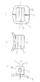
図1は本発明の小臼歯用チューブの一実施例を示す説明図で、図1の(a)は本発明の小臼歯用チューブの一実施例を示す正面図、図1の(b)はそのI−I線での断面図、図1の(c)はその側面の断面図である。
図1の実施例は上顎の第一、第二小臼歯に使用される小臼歯用チューブの例を示したものである。
図1において、10は、アーチワイヤーの挿入されるチューブである。20は、角形の断面を持ったチューブ10の貫通孔である。30は、チューブ10が取り付けられる板状のベースである。32は板状のベース30に設けられた基準溝である。
チューブ10はベース30を介して小臼歯の所定の位置に、基準溝32を目安にして固着される。図1に示すように、本発明の小臼歯用のチューブは、ベース30に上にチューブ10をアーチワイヤー貫通孔20が略水平方向になるように取り付けられている。
【0012】
図1の(c)に示すように、チューブ10はベース30の面の垂線31に対して、貫通孔20の中心を通る線21が一定の角度θの傾きを持って取り付けられている。このベース30の面の垂線31に対して、貫通孔20の中心を通る線21の傾き角度θは、チューブが使用される小臼歯によって異なっている。
図1に示した本発明の小臼歯用のチューブは、上顎の左右の第一,第二小臼歯の4本の小臼歯に使用されるものであるが、上顎の第一,第二小臼歯、下顎の第一小臼歯、下顎の第二小臼歯に使用されるチューブは、それぞれの小臼歯に応じてベース30の面の垂線31に対して、貫通孔20の中心を通る線21の傾き角度θが変えられている。
【0013】
図2は本発明の小臼歯用チューブの他の実施例を示す説明図で、図2の(a)は本発明の小臼歯用チューブの一実施例を示す正面図であり、図3の(b)はそのI−I線での断面図、図2の(c)はその側面の断面図である。
図2の実施例は下顎の第一小臼歯に使用される小臼歯用チューブの例を示したものである。
図2において、10は、アーチワイヤーの挿入されるチューブである。20は、角形の断面を持ったチューブ10の貫通孔である。30は、チューブ10が取り付けられる板状のベース、32は板状のベース30に設けられた基準溝である。板状のベース30の形状は図1に示した上顎の第一小臼歯、第二小臼歯に使用されるものとは形状が異なっている。
チューブ10はベース30を介して下顎の第一小臼歯に固着される。図2に示すように、本発明の小臼歯用のチューブは、ベース30に上にチューブ10をアーチワイヤー貫通孔20が略水平方向になるように取り付けられている。
図2の(c)に示すように、チューブ10はベース30の面の垂線31に対して、貫通孔20の中心を通る線21が一定の角度θの傾きを持って取り付けられている。このベース30の面の垂線31に対して、貫通孔20の中心を通る線21の傾き角度θは、図1に示した上顎の第一小臼歯、第二小臼歯のものとは異なっており、又チューブが使用される下顎の第一小臼歯、第二小臼歯によっても異なっている。
【0014】
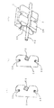
図3は本発明の小臼歯用チューブの他の実施例を示す説明図である。図3の実施例は、チューブの貫通孔の入口を円錐の漏斗状にしてアーチワイヤーの挿入を容易にしたものである。
図3の(a)は本発明の小臼歯用チューブの一実施例を示す正面図、図3の(b)はそのI−I線での断面図、図3の(c)はその側面の断面図である。
図3の実施例は上顎の第一小臼歯、第二小臼歯に使用される小臼歯用チューブの例を示したものである。
図3において、10は、アーチワイヤーの挿入されるチューブである。20は、角形の断面を持ったチューブ10の貫通孔である。22,23はチューブの貫通孔20の入口に設けられた円錐の漏斗状のアーチワイヤーの導入部である。
30は、チューブ10が取り付けられる板状のベースである。チューブ10はベース30を介して小臼歯に固着される。図1に示すように、本発明の小臼歯用のチューブは、ベース30上にチューブ10をアーチワイヤー貫通孔20が略水平方向になるように取り付けられている。
【0015】
図3の(c)に示すように、チューブ10はベース30の面の垂線31に対して、貫通孔20の中心を通る線21が一定の角度θの傾きを持って取り付けられている。このベース30の面の垂線31に対して、貫通孔20の中心を通る線21の傾き角度θは、チューブが使用される小臼歯によって異なっている。
図3に示した本発明の小臼歯用のチューブは、上顎の左右の第一小臼歯、第二小臼歯の4本の小臼歯に使用されるものであるが、下顎の第一小臼歯、第二小臼歯に使用されるチューブは、それぞれの小臼歯に応じてベース30の面の垂線31に対して、貫通孔20の中心を通る線21の傾き角度θが変えられている。
図3の実施例では、チューブの貫通孔の入口に円錐の漏斗状のアーチワイヤーの導入部を設けたために、アーチワイヤーをチューブの貫通孔に挿入する作業が容易になる。
【0016】
図4は本発明の小臼歯用チューブの更に他の実施例を示す説明図である。
図4の実施例は下顎の第一小臼歯に使用される小臼歯用チューブの例を示したもので、図3と同様にチューブの貫通孔の入口を円錐の漏斗状にしてアーチワイヤーの挿入を容易にしたものである。
図4の(a)は本発明の小臼歯用チューブの一実施例を示す正面図であり、図4の(b)はそのI−I線での断面図、図4の(c)はその側面の断面図である。図4において、10は、アーチワイヤーの挿入されるチューブである。20は、角形の断面を持ったチューブ10の貫通孔である。22,23はチューブの貫通孔20の入口に設けられた円錐の漏斗状のアーチワイヤーの導入部である。
30は、チューブ10が取り付けられる板状のベースである。板状のベース30の形状は図1に示した上顎の第一小臼歯、第二小臼歯に使用されるものとは形状が異なっている。
チューブ10はベース30を介して小臼歯に固着される。図4に示すように、本発明の小臼歯用のチューブは、ベース30に上にチューブ10をアーチワイヤー貫通孔20が略水平方向になるように取り付けられている。
【0017】
図4の(c)に示すように、チューブ10はベース30の面の垂線31に対して、貫通孔20の中心を通る線21が一定の角度θの傾きを持って取り付けられている。このベース30の面の垂線31に対して、貫通孔20の中心を通る線21の傾き角度θは、図1に示した上顎の第一小臼歯、第二小臼歯のものとは異なっており、又チューブが使用される下顎の第一小臼歯、第二小臼歯によっても異なっている。
図4の実施例では、図3と同様にチューブの貫通孔の入口に円錐の漏斗状のアーチワイヤーの導入部を設けたために、下顎の第一小臼歯、第二小臼歯のチューブの貫通孔にアーチワイヤーを挿入する作業が容易になる。
【0018】
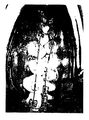
図5は本発明の小臼歯用チューブを使用して歯列矯正を行っている様子を示す図である。
治療に際しては、チューブのベース30の接着面に塗布した接着剤によってチューブを小臼歯の面に固定する。その後、アーチワイヤーが装着される。
図5に示すように、上顎と下顎の第一小臼歯、第二小臼歯にそれぞれのチューブが固定され、各チューブにアーチワイヤーが通され矯正が行われる。
1次治療により大まかに歯列矯正を行う場合には、アーチワイヤーに断面丸形のものを用いたり、細い角形のものを用ることによりアーチワイヤーの固定を緩やかなものとすることが出来る。
【0019】
歯列を正確な位置に矯正する二次治療の段階においてトルク移動を行いたい場合は、アーチワイヤーに角形のものを用いる。アーチワイヤーのサイズはチューブの貫通孔に応じた大きさになっており、アーチワイヤーはチューブの貫通孔にきっちりと嵌め込むことができる。
本発明の小臼歯用チューブでは、アーチワイヤーはチューブの挿入孔を貫通することにより固定されるので、アーチワイヤーはチューブの挿入孔の4面、即ち上面,下面,両側面で固定される構成となっている。この4面の固定は、咀嚼等を行ってアーチワイヤーに力が加わってもアーチワイヤーを常時4面からしっかりと固定することができるので所望のトルク移動を可能となる。
【0020】
本発明では、アーチワイヤーの形を選択することで、緩やかな固定からしっかりとした固定まで実現できるので、本発明の歯列の粗揃え段階から正位置矯正段階まですべての治療段階に対応でき、且つ表面が凹凸の少ない形状であるから、歯垢が付き難く、また壊れ難く、加えて歯磨きの際に歯ブラシも届き易いので清掃を容易に行うことができる。
本発明の小臼歯用チューブは、アーチワイヤーの装着には、チューブの貫通孔にアーチワイヤーを通すだけで良いので、施術作業が容易であり、チューブに装着されたアーチワイヤーは容易に外れる様なことはない。
本発明の小臼歯用チューブを使用した歯列矯正では、従来のような医師の勘によって固定ワイヤーの結紮強度を加減しアーチワイヤーの固定程度を調整する必要が無いので、医師の技能に左右されることがなくなり、固定の強さはアーチワイヤーの形状を選択することで自動的に設定されるために、医師の技能によらない一定の固定強さが実現できる。
【0021】
【発明の効果】
以上の説明より明らかなように、本発明の小臼歯用チューブは、角形の断面を持ったアーチワイヤーの貫通孔を持ったチューブと、このチューブが取り付けられる板状のベースとよりなり、前記チューブはその貫通孔の中心を通る線がベースの面の垂線に対して一定の角度の傾きを持ってベースに取り付けられており、チューブをベースを介して小臼歯に固着してアーチワイヤーをチューブ貫通孔通して取り付けるようにすることにより、アーチワイヤーを安定に固定出来るようにしたものである。
本発明においては、アーチワイヤーの固定をチューブにより行うようにしたために、口の奥に位置しているために作業のしにくい小臼歯に対して前方からアーチワイヤーを容易に装着することができるので、アーチワイヤー装着施術の過程で、アーチワイヤーを締結により固定やロックピンによる固定を行う必要が無く、アーチワイヤーが勝手には外れることがなく、施術作業性が非常に良好なものとなる。又、本発明の小臼歯用チューブは表面が凹凸の少ない形状であるから、歯垢が付き難く、また壊れ難く、加えて歯磨きの際に歯ブラシも届き易いので清掃を容易に行うことができる。
【図面の簡単な説明】
【図1】 本発明の小臼歯用チューブの一実施例を示す説明図で、図1の(a)は本発明の小臼歯用チューブの一実施例を示す正面図、図1の(b)はそのI−I線での断面図、図1の(c)はその側面の断面図である。
【図2】 本発明の小臼歯用チューブの他の実施例を示す説明図で、下顎の第一小臼歯に使用される小臼歯用チューブの例を示したものである。
【図3】 本発明の小臼歯用チューブの他の実施例を示す説明図で、チューブの貫通孔の入口を円錐の漏斗状にしてアーチワイヤーの挿入を容易にしたものである。
【図4】 本発明の小臼歯用チューブの更に他の実施例を示す説明図で、図3と同様にチューブの貫通孔の入口を円錐の漏斗状にしてアーチワイヤーの挿入を容易にしたもので、下顎の第一小臼歯に使用される小臼歯用チューブの例を示したものである。
【図5】 本発明の小臼歯用チューブを使用して歯列矯正を行っている様子を示す図である。
【図6】 従来より広く使用されている歯列矯正具のブラケットとアーチワイヤーを使用した歯列矯正治療方法の一例を示したものである。
【符号の説明】
10・・・アーチワイヤーの挿入されるチューブ,
20・・・角形の断面を持ったチューブ10の貫通孔,
22,23・・・チューブの貫通孔20の入口に設けられた円錐の漏斗状のアーチワイヤーの導入部,
30・・・チューブ10が取り付けられる板状のベース,
31・・・ベース30の面の垂線,
32・・・基準溝,
40・・・ブラケット,
50・・・アーチワイヤー,
60・・・締結ワイヤー,[0001]
BACKGROUND OF THE INVENTION
The present invention relates to a premolar tube used for dental orthodontics. The premolar tube of the present invention can stably attach an arch wire without the need for an auxiliary ligation wire or a lock pin.
[0002]
[Prior art]
Teeth that do not have normal teeth such as double teeth not only look bad, but also easily cause plaque and cause dental decay and alveolar pyorrhea. It has been broken.
In the orthodontic treatment method, an orthodontic appliance is fixed to the surface of a tooth with an adhesive or the like, and an archwire is passed through the orthodontic appliance to press the teeth, thereby moving the orthodontics to a correct position.
[0003]
An example of an orthodontic treatment method using a bracket and an archwire of an orthodontic appliance that has been widely used conventionally is shown in FIG.
6A is a perspective view showing a bracket, an arch wire, and a fastening wire, and FIGS. 6B and 6C are cross-sectional views taken along a line I-I in FIG. 6A. .
In FIG. 6, 40 is a bracket, 50 is an arch wire, and 60 is a fastening wire.
The
[0004]
In the orthodontic treatment, first, the orthodontics is roughly corrected as a primary treatment. The fixing of the
For this reason, the
As shown in FIG. 6B, when the
[0005]
Tooth whose teeth are roughly arranged by the primary treatment is subjected to secondary treatment for correcting the dentition to an accurate position. In the secondary treatment, the
As shown in FIG. 6 (c), when the
[0006]
Various orthodontic appliances have been put to practical use other than those for fastening an arch wire to a fixed base with the above fastening wires.
For example, a method is proposed in which a lock pin is used in place of the
In this method, the arch wire is fixed by inserting the arch wire from above into a horizontally deep arch wire groove provided on the bracket and passing the lock pin through the lock pin groove. It is stopped so as not to come off.
[0007]
[Problems to be solved by the invention]
In the conventional method of fixing the arch wire to the bracket, it is difficult to keep the static frictional force of the fixing strength of the arch wire and the bracket at a constant value. Needed skill.
In addition, when the arch wire is fixed to the bracket by fastening, the static friction force is about 60 gf when the rubber ligation wire is used, and may exceed 200 gf when the static friction force of the ligation wire is large. This static frictional force due to the fastening can hinder the teeth from moving to the correct position and can sometimes cause unwanted tooth movement. In addition, the static frictional force due to the fastening has a problem that the movement of the tooth sliding on the arch wire is also hindered. For this reason, development of the fixing method which maintains the fixed strength of an arch wire and a bracket at a fixed value is desired.
[0008]
In addition, the bracket that is currently used has a lot of complex irregularities, and in addition, because the irregularities further increase by fastening with wires etc. for fixing, food tends to accumulate in the irregularities, Moreover, since brushing with a toothbrush is difficult to achieve, there is a problem that plaque accumulates and the mouth becomes unsanitary. In addition, there is a problem that the apparatus is complicated and easily broken.
Therefore, there is a demand for the development of an orthodontic appliance that can maintain the fixing strength between the archwire and the bracket at a constant value, has a simple structure, and does not require skill for use.
The present invention has been made in view of the above problems, and can perform torque movement without the need for an auxiliary ligation wire, does not require a fixing wire, is difficult to have plaque, and can be attached to an arch wire. An object of the present invention is to provide an easy orthodontic appliance.
[0009]
[Means for Solving the Problems]
The present invention comprises a tube having a through hole of an arch wire having a square cross section and a plate-like base to which the tube is attached, and the tube has a line passing through the center of the through hole on the surface of the base. Attached to the base with a certain angle of inclination with respect to the perpendicular, the tube is fixed to the premolar via the base, and the archwire is attached through the tube through hole to achieve a premolar tube By doing so, the archwire can be stably fixed.
In the present invention, since the arch wire is fixed by the tube, the arch wire can be easily attached from the front to the premolar which is difficult to work because it is located in the back of the mouth. In the course of the archwire mounting treatment, it is not necessary to fix the archwire by fastening or fixing with a lock pin, the archwire does not come off arbitrarily, and the workability is very good.
[0010]
For this reason, in the present invention, it is possible to attach an arch wire without requiring an auxiliary ligation wire, a lock pin, or the like for the premolars, and it is easy to prevent plaque from being broken with a simple structure. It is possible to provide a premolar tube that can be easily attached with an archwire.
In the premolar tube of the present invention, since the archwire is fixed by penetrating the tube insertion hole, the archwire is fixed on the four surfaces of the tube insertion hole, that is, the upper surface, the lower surface, and both side surfaces. It has become. The fixing of the four surfaces enables desired torque movement because the arch wire can always be firmly fixed from the four surfaces even if a force is applied to the arch wire by chewing or the like.
[0011]
DETAILED DESCRIPTION OF THE INVENTION
【Example】
FIG. 1 is an explanatory view showing an embodiment of the premolar tube of the present invention. FIG. 1 (a) is a front view showing an embodiment of the premolar tube of the present invention, and FIG. FIG. 1C is a cross-sectional view taken along the line II, and FIG.
The embodiment of FIG. 1 shows an example of a premolar tube used for the first and second premolars of the upper jaw.
In FIG. 1, 10 is a tube into which an archwire is inserted.
The
[0012]
As shown in FIG. 1C, the
The premolar tube of the present invention shown in FIG. 1 is used for the four premolars of the first and second premolars on the left and right sides of the upper jaw. The tube used for the first premolar of the lower jaw and the second premolar of the lower jaw is inclined with respect to a
[0013]
FIG. 2 is an explanatory view showing another embodiment of the premolar tube of the present invention. FIG. 2A is a front view showing an embodiment of the premolar tube of the present invention. b) is a cross-sectional view taken along the line II, and FIG. 2C is a cross-sectional view of the side surface thereof.
The embodiment of FIG. 2 shows an example of a premolar tube used for the first premolar of the lower jaw.
In FIG. 2, 10 is a tube into which an archwire is inserted.
The
As shown in FIG. 2C, the
[0014]
FIG. 3 is an explanatory view showing another embodiment of the premolar tube of the present invention. In the embodiment shown in FIG. 3, the entrance of the tube through-hole is formed in a conical funnel shape to facilitate the insertion of the archwire.
3 (a) is a front view showing an embodiment of the premolar tube of the present invention, FIG. 3 (b) is a cross-sectional view taken along the line II, and FIG. 3 (c) is a side view thereof. It is sectional drawing.
The embodiment of FIG. 3 shows an example of a premolar tube used for the upper first premolar and second premolar.
In FIG. 3, 10 is a tube into which an archwire is inserted.
[0015]
As shown in (c) of FIG. 3, the
The tube for premolars of the present invention shown in FIG. 3 is used for the four premolars of the upper and lower first premolars and the second premolars. In the tube used for the second premolar, the inclination angle θ of the
In the embodiment of FIG. 3, since the introduction portion of the conical funnel-shaped arch wire is provided at the inlet of the through hole of the tube, the operation of inserting the arch wire into the through hole of the tube becomes easy.
[0016]
FIG. 4 is an explanatory view showing still another embodiment of the premolar tube of the present invention.
The embodiment of FIG. 4 shows an example of a premolar tube used for the first premolar of the lower jaw. Like the case of FIG. Is made easier.
4 (a) is a front view showing an embodiment of the premolar tube of the present invention, FIG. 4 (b) is a cross-sectional view taken along the line I-I, and FIG. It is sectional drawing of a side surface. In FIG. 4, 10 is a tube into which an archwire is inserted.
The
[0017]
As shown in FIG. 4C, the
In the embodiment of FIG. 4, since the introduction part of the conical funnel-shaped arch wire is provided at the entrance of the through hole of the tube as in FIG. 3, the through hole of the tube of the first premolar of the lower jaw and the tube of the second premolar The work of inserting the archwire into the door becomes easy.
[0018]
FIG. 5 is a view showing a state in which orthodontics is performed using the premolar tube of the present invention.
In the treatment, the tube is fixed to the surface of the premolars with an adhesive applied to the adhesive surface of the
As shown in FIG. 5, each tube is fixed to the first premolar and the second premolar of the upper jaw and the lower jaw, and an archwire is passed through each tube for correction.
When the orthodontic treatment is roughly performed by the primary treatment, the arch wire can be loosely fixed by using a arch wire having a round cross section or a thin square.
[0019]
When torque transfer is desired in the secondary treatment stage where the dentition is corrected to an accurate position, a square arch wire is used. The size of the arch wire is sized according to the through hole of the tube, and the arch wire can be fitted into the through hole of the tube exactly.
In the premolar tube of the present invention, since the archwire is fixed by penetrating the tube insertion hole, the archwire is fixed on the four surfaces of the tube insertion hole, that is, the upper surface, the lower surface, and both side surfaces. It has become. The fixing of the four surfaces enables a desired torque movement because the arch wire can always be firmly fixed from the four surfaces even if a force is applied to the arch wire by chewing or the like.
[0020]
In the present invention, by selecting the shape of the archwire, it can be realized from loose fixation to firm fixation, so it can correspond to all treatment stages from the rough alignment stage of the dentition of the present invention to the orthodontic correction stage, In addition, since the surface has a shape with few irregularities, it is difficult for plaque to adhere and break, and in addition, the toothbrush is easy to reach when brushing, so that cleaning can be performed easily.
The premolar tube of the present invention can be attached to the archwire by simply passing the archwire through the through hole of the tube, so that the surgical operation is easy, and the archwire attached to the tube can be easily detached. There is nothing.
In orthodontics using the premolar tube of the present invention, it is not necessary to adjust the ligature strength of the fixing wire and adjust the degree of fixation of the arch wire by conventional doctor's intuition, so it depends on the skill of the doctor. Since the fixed strength is automatically set by selecting the shape of the archwire, a fixed strength independent of the skill of the doctor can be realized.
[0021]
【The invention's effect】
As is clear from the above description, the premolar tube of the present invention comprises a tube having an archwire through-hole having a square cross section and a plate-like base to which the tube is attached. Is attached to the base so that the line passing through the center of the through-hole has a fixed angle with respect to the perpendicular to the surface of the base. By attaching it through a hole, the archwire can be fixed stably.
In the present invention, since the arch wire is fixed by the tube, the arch wire can be easily attached from the front to the premolar which is difficult to work because it is located in the back of the mouth. In the course of the archwire mounting treatment, it is not necessary to fix the archwire by fastening or fixing with a lock pin, the archwire does not come off arbitrarily, and the workability is very good. In addition, since the premolar tube of the present invention has a shape with less irregularities, it is difficult to get plaque and breakage, and in addition, the toothbrush easily reaches when brushing, so that cleaning can be performed easily.
[Brief description of the drawings]
FIG. 1 is an explanatory view showing an embodiment of the premolar tube of the present invention. FIG. 1 (a) is a front view showing an embodiment of the premolar tube of the present invention, and FIG. 1 (b). Is a cross-sectional view taken along the line II, and FIG. 1C is a cross-sectional view of the side surface thereof.
FIG. 2 is an explanatory view showing another embodiment of the premolar tube of the present invention, showing an example of a premolar tube used for the first premolar of the lower jaw.
FIG. 3 is an explanatory view showing another embodiment of the premolar tube according to the present invention, in which the inlet of the through hole of the tube is made into a conical funnel shape to facilitate the insertion of the archwire.
FIG. 4 is an explanatory view showing still another embodiment of the premolar tube of the present invention, in which the entrance of the through hole of the tube is made into a conical funnel shape and the insertion of the arch wire is facilitated similarly to FIG. The example of the tube for the premolar used for the first premolar of the lower jaw is shown.
FIG. 5 is a view showing a state where orthodontics is performed using the premolar tube of the present invention.
FIG. 6 shows an example of an orthodontic treatment method using a bracket and an archwire of an orthodontic appliance that has been widely used conventionally.
[Explanation of symbols]
10 ... Tube into which the archwire is inserted,
20 ... a through hole of the
22, 23... Introduction part of a conical funnel-shaped arch wire provided at the inlet of the through-
30 ... A plate-like base to which the
31 ... perpendicular to the surface of the
32 ... reference groove,
40 ... Bracket,
50 ... Archwire,
60 ... Fastening wire,
Claims (5)
Priority Applications (1)
| Application Number | Priority Date | Filing Date | Title |
|---|---|---|---|
| JP2000259513A JP4375889B2 (en) | 2000-08-29 | 2000-08-29 | Premolar tube |
Applications Claiming Priority (1)
| Application Number | Priority Date | Filing Date | Title |
|---|---|---|---|
| JP2000259513A JP4375889B2 (en) | 2000-08-29 | 2000-08-29 | Premolar tube |
Publications (2)
| Publication Number | Publication Date |
|---|---|
| JP2002065701A JP2002065701A (en) | 2002-03-05 |
| JP4375889B2 true JP4375889B2 (en) | 2009-12-02 |
Family
ID=18747686
Family Applications (1)
| Application Number | Title | Priority Date | Filing Date |
|---|---|---|---|
| JP2000259513A Expired - Lifetime JP4375889B2 (en) | 2000-08-29 | 2000-08-29 | Premolar tube |
Country Status (1)
| Country | Link |
|---|---|
| JP (1) | JP4375889B2 (en) |
Families Citing this family (1)
| Publication number | Priority date | Publication date | Assignee | Title |
|---|---|---|---|---|
| EP3328312B1 (en) * | 2015-07-31 | 2020-09-09 | Erskine Products Pty Ltd | An orthodontic anchorage device |
-
2000
- 2000-08-29 JP JP2000259513A patent/JP4375889B2/en not_active Expired - Lifetime
Also Published As
| Publication number | Publication date |
|---|---|
| JP2002065701A (en) | 2002-03-05 |
Similar Documents
| Publication | Publication Date | Title |
|---|---|---|
| JP3751562B2 (en) | Rapid orthodontic orthodontic method by cortical osteotomy and its orthodontic appliance | |
| KR101723674B1 (en) | Lingual orthodontic system | |
| KR102642186B1 (en) | Orthodontic system with variable-sized archwire slots | |
| US4209906A (en) | Orthodontic appliance (bracket and lock pin) | |
| CN205964198U (en) | A wire rod hander and unscrambler for tooth for corrective therapy of tooth jaw | |
| JP3512466B2 (en) | Orthodontic bracket | |
| JPH0371896B2 (en) | ||
| US5125831A (en) | Orthodontic bracket with bi-directional hook | |
| US4614497A (en) | Orthodontic bracket for a doubled-over tie ligature | |
| KR100379987B1 (en) | Convertable resin core system for positioning a bracket at a predetermined point of tooth surface | |
| US20050244781A1 (en) | Orthodontic treatment method for concurrent correction of multiple conditions | |
| CN1997326A (en) | Orthodontic bracket and clip | |
| WO1999042056A1 (en) | Orthodontic appliance | |
| HUP0303023A2 (en) | Orthodontic appliance | |
| US20070207436A1 (en) | Orthodontic Appliance | |
| JPS6384548A (en) | Orthodontic apparatus for dilating dental arch | |
| US7396230B2 (en) | Molar orthodontic brackets having a hinged bracket cover | |
| KR20180103761A (en) | Jig integrated bracket for orthodontic treatment and manufacturing method thereof | |
| JP2007522852A (en) | Lingual bracket | |
| US7625206B2 (en) | Method of orthodontic treatment | |
| US6364659B1 (en) | Orthodontic bite opener | |
| CA2477352C (en) | Orthodontic appliance and method | |
| KR102106820B1 (en) | The device for fixing a apparatus in the mouth | |
| JP4375889B2 (en) | Premolar tube | |
| US4875856A (en) | Orthodontic appliance for closing spaces and correcting malocclusion |
Legal Events
| Date | Code | Title | Description |
|---|---|---|---|
| A621 | Written request for application examination |
Free format text: JAPANESE INTERMEDIATE CODE: A621 Effective date: 20070803 |
|
| A977 | Report on retrieval |
Free format text: JAPANESE INTERMEDIATE CODE: A971007 Effective date: 20090423 |
|
| A131 | Notification of reasons for refusal |
Free format text: JAPANESE INTERMEDIATE CODE: A131 Effective date: 20090519 |
|
| A521 | Written amendment |
Free format text: JAPANESE INTERMEDIATE CODE: A523 Effective date: 20090617 |
|
| A521 | Written amendment |
Free format text: JAPANESE INTERMEDIATE CODE: A523 Effective date: 20090617 |
|
| TRDD | Decision of grant or rejection written | ||
| A01 | Written decision to grant a patent or to grant a registration (utility model) |
Free format text: JAPANESE INTERMEDIATE CODE: A01 Effective date: 20090825 |
|
| A01 | Written decision to grant a patent or to grant a registration (utility model) |
Free format text: JAPANESE INTERMEDIATE CODE: A01 |
|
| A61 | First payment of annual fees (during grant procedure) |
Free format text: JAPANESE INTERMEDIATE CODE: A61 Effective date: 20090908 |
|
| R150 | Certificate of patent (=grant) or registration of utility model |
Free format text: JAPANESE INTERMEDIATE CODE: R150 |
|
| FPAY | Renewal fee payment (prs date is renewal date of database) |
Free format text: PAYMENT UNTIL: 20120918 Year of fee payment: 3 |