JP4380331B2 - How to protect the iron core of a rotary furnace - Google Patents
How to protect the iron core of a rotary furnace Download PDFInfo
- Publication number
- JP4380331B2 JP4380331B2 JP2004004527A JP2004004527A JP4380331B2 JP 4380331 B2 JP4380331 B2 JP 4380331B2 JP 2004004527 A JP2004004527 A JP 2004004527A JP 2004004527 A JP2004004527 A JP 2004004527A JP 4380331 B2 JP4380331 B2 JP 4380331B2
- Authority
- JP
- Japan
- Prior art keywords
- temperature
- furnace body
- cooling water
- furnace
- iron
- Prior art date
- Legal status (The legal status is an assumption and is not a legal conclusion. Google has not performed a legal analysis and makes no representation as to the accuracy of the status listed.)
- Expired - Fee Related
Links
Images







Landscapes
- Waste-Gas Treatment And Other Accessory Devices For Furnaces (AREA)
- Muffle Furnaces And Rotary Kilns (AREA)
Description
本発明は、回転炉の鉄皮さらには耐火物の保護方法に関する。 The present invention relates to a method for protecting an iron skin of a rotary furnace and further a refractory.
ロータリーキルンに代表される回転炉は、熱効率の向上と耐火物の溶損防止とを主目的として炉体を回転させながら燃料を燃焼させることによって、被加熱物を加熱・溶解する炉である。 A rotary kiln represented by a rotary kiln is a furnace that heats and melts an object to be heated by burning fuel while rotating the furnace body mainly for the purpose of improving thermal efficiency and preventing refractory melts.
このような回転炉の操業時における炉内各部の温度は均一ではないために、耐火物の損耗の進行速度が炉内各部で異なる。他の耐火物よりも損耗が進行した耐火物の近傍の鉄皮は、他の部分よりも温度が上昇して、最終的に溶損に至る。これを防ぐために予め定めた一定期間毎に耐火物の補修を行っているが、これにより、回転炉の稼働率の低下や補修コストの増大等につながり、回転炉の操業効率が低下していた。このため、鉄皮の温度の上昇や耐火物の損耗の進行を抑制しながら、できるだけ長い期間にわたって継続して操業することができる技術が、強く求められている。 Since the temperature of each part in the furnace during operation of such a rotary furnace is not uniform, the progress rate of wear of the refractory varies among the parts in the furnace. The iron skin near the refractory that has been worn out more than the other refractories has a higher temperature than the other portions, and eventually reaches a melting point. In order to prevent this, refractories are repaired at predetermined intervals, which leads to a decrease in the operating rate of the rotary furnace and an increase in repair costs, and the operation efficiency of the rotary furnace has been reduced. . For this reason, there is a strong demand for a technique capable of continuously operating for as long a period as possible while suppressing the temperature rise of the iron skin and the progress of wear of the refractory.
特許文献1には、炉体の周囲に設けた水冷ジャケットの内部に冷却水を供給して炉体全体を一様に冷却することによって、回転炉の耐火物を保護する発明が開示されている。
また、特許文献2や特許文献3には、回転炉の炉体の出口付近に補助バーナを設けて炉体の出口付近においても燃焼を行うことによって、出口付近におけるスラグの付着を防止する発明が開示されている。
特許文献1により開示された発明では、鉄皮の温度を測定していないため、耐火物の局部的な損耗を発見することが不可能であり、鉄皮の保護対策を的確なタイミングで行うことができない。仮に、鉄皮の温度を測定したとしても、鉄皮は常に水冷されているため、局部的な損耗を生じた位置を検知して特定することは困難である。さらに、この発明では、耐火物の損耗の度合いには関係なく炉体全体を一様に冷却するため、非損耗部の耐火物を過剰に冷却してしまうこととなる。このため、過剰に冷却された耐火物が熱収縮して非損耗部の耐火物まで損傷するおそれもある。このため、特許文献1により開示された発明によっても、耐火物の寿命は高々1ヶ月程度にしか過ぎず、回転炉の耐火物の損耗を効果的に抑制することはできなかった。
In the invention disclosed in
また、特許文献2又は特許文献3により開示された発明によっても、耐火物の損耗を効果的に抑制することはできない。以下、この理由を添付図面を参照しながら説明する。
図1は、ロータリーキルンに代表される回転炉1の炉体2の長手方向への断面の一例を模式的に示す説明図であり、図2はこの回転炉1の炉体2の長手方向への温度分布の一例を示すグラフである。さらに、図3は、ロータリーキルンに代表される回転炉1の炉体2に特許文献2又は特許文献3により開示された発明を適用した場合の長手方向への断面の一例を模式的に示す説明図である。
In addition, even with the invention disclosed in
FIG. 1 is an explanatory view schematically showing an example of a cross section in the longitudinal direction of a
図1及び図2に示すように、回転炉1の炉体2の入口付近には燃焼バーナ3が設置されているため、燃焼バーナ3が形成する火炎4の先端(図1及び図2におけるA点付近)には、長手方向に第1の温度ピークが形成される。一方、炉体2の出口付近では燃焼バーナ3が形成する火炎4が到達し難いことから、スラグ5が付着して堆積し易くなり、図1及び図2におけるB点付近で溶融還元鉄が滞って溶銑溜まり6が形成される。このため、そのB点付近でも温度が高くなり、長手方向に第2の温度ピークが形成される。
As shown in FIGS. 1 and 2, since the
特許文献2又は特許文献3により開示された発明によれば、炉体2の出口の手前付近に設けた補助バーナ7により形成される火炎8の先端であるB点付近に形成される溶銑溜まり6を解消することはできるものの、補助バーナ7の火炎8の先端付近に第2の温度ピークを生じてしまう。
According to the invention disclosed in
このように、特許文献2又は特許文献3により開示された発明によっても、回転炉1の炉体2の温度分布は、燃焼バーナ3との位置関係により炉体2の長手方向の全長で二つのピークが形成されて一様にはならない。このため、耐火物の損耗を効果的に抑制し、この損耗に起因した鉄皮の溶損を防止することはできなかった。
Thus, even with the invention disclosed in
本発明の目的は、回転炉の耐火物の損耗を効果的に抑制することができ、これにより、従来は1ヶ月程度であった補修周期を例えば約6ヶ月程度にまで大幅に延長できることによって保守コストの抑制や稼働率の向上等を図ることができる回転炉の鉄皮の保護方法を提供することである。 The object of the present invention is to effectively suppress the wear of the refractory in the rotary furnace, and thereby maintenance can be carried out by greatly extending the repair period, which was conventionally about 1 month, to about 6 months, for example. An object of the present invention is to provide a method for protecting the iron core of a rotary furnace capable of reducing costs and improving the operating rate.
本発明は、回転炉の炉体を構成する鉄皮の表面の温度を、炉体円周方向の各部位毎に測定し、測定したこの温度が予め定めた管理温度域を逸脱した部位に対して、この部位が鉄皮の外面に冷却水を供給する冷却水供給部を通過する時に、所望の量の冷却水を供給することによって、逸脱した部位の温度を管理温度域内とするとともに、管理温度域を逸脱した炉体円周方向の部位が炉体下部を通過する時以外の時には、炉体の回転速度を(1/20)rpm以上(1/10)rpm以下とし、管理温度域を逸脱した炉体円周方向の部位が炉体下部を通過する時には、炉体の回転速度を(1/10)rpm超とすることを特徴とする回転炉の鉄皮の保護方法である。 In the present invention, the temperature of the surface of the iron shell constituting the furnace body of the rotary furnace is measured for each part in the furnace body circumferential direction, and the measured temperature deviates from a predetermined management temperature range. Then, when this part passes through the cooling water supply part that supplies the cooling water to the outer surface of the iron skin, by supplying the desired amount of cooling water, the temperature of the deviated part is set within the management temperature range and is managed. When the part in the circumferential direction of the furnace body that deviates from the temperature range passes through the lower part of the furnace body, the rotational speed of the furnace body is set to (1/20) rpm or more (1/10) rpm or less, and the management temperature range is set to When the deviated portion in the circumferential direction of the furnace body passes through the lower part of the furnace body, the rotation speed of the furnace body is set to exceed (1/10) rpm .
また、本発明は、回転炉の炉体を構成する鉄皮の表面の温度を、炉体長手方向の各部位毎及び炉体円周方向の各部位毎に測定し、炉体長手方向について測定した温度が予め定めた管理温度域を逸脱した部位に対して、炉体長手方向に配置した複数の冷却水供給部それぞれから鉄皮の外面に供給される冷却水の量を、複数の冷却水供給部それぞれ毎に個別に調整するとともに、炉体円周方向について測定した温度が予め定めた管理温度域を逸脱した部位が鉄皮の外面に冷却水を供給する冷却水供給部を通過する時に、所望の量の冷却水を供給することによって、逸脱した部位の温度を管理温度域内とするとともに、管理温度域を逸脱した炉体円周方向の部位が炉体下部を通過する時に以外の時には、炉体の回転速度を(1/20)rpm以上(1/10)rpm以下とし、管理温度域を逸脱した炉体円周方向の部位が炉体下部を通過する時には、炉体の回転速度を(1/10)rpm超とすることを特徴とする回転炉の鉄皮の保護方法である。 Further, the present invention measures the temperature of the surface of the iron skin constituting the furnace body of the rotary furnace for each part in the furnace body longitudinal direction and each part in the furnace body circumferential direction, and measures the furnace body longitudinal direction. The amount of cooling water supplied to the outer surface of the iron shell from each of the plurality of cooling water supply units arranged in the longitudinal direction of the furnace body with respect to the portion where the temperature deviated from the predetermined management temperature range is set to a plurality of cooling water. When the part where the temperature measured in the circumferential direction of the furnace body deviates from the predetermined management temperature range passes through the cooling water supply part that supplies the cooling water to the outer surface of the iron skin while individually adjusting each supply part By supplying a desired amount of cooling water, the temperature of the deviated part is set within the control temperature range, and when the part in the furnace circumferential direction deviating from the control temperature range passes through the lower part of the furnace body , , The rotational speed of the furnace body is (1/20) rpm or more ( / 10) and rpm or less, the rotation site of deviates from the control temperature range furnace body circumferentially as it passes through the furnace bottom, which is characterized in that the rotational speed of the furnace body and (1/10) rpm than This is a method for protecting the iron skin of the furnace.
これらの本発明に係る回転炉の鉄皮の保護方法において、冷却水供給部からの冷却水の供給量を、鉄皮の温度実績に基づいて、修正することが望ましい。
これらの本発明に係る回転炉の鉄皮の保護方法において、さらに、冷却水を供給した後に一定時間冷却水の供給を停止してから、鉄皮の温度を測定し、この温度が再度上昇して温度管理域を逸脱する場合に冷却水の供給を再開することが望ましい。
In these methods for protecting the iron core of a rotary furnace according to the present invention, it is desirable to correct the supply amount of the cooling water from the cooling water supply unit based on the actual temperature of the iron skin.
In these methods for protecting the iron skin of a rotary furnace according to the present invention, the supply of the cooling water is stopped for a certain time after the cooling water is supplied, and then the temperature of the iron skin is measured, and this temperature rises again. It is desirable to restart the supply of cooling water when the temperature deviates from the temperature control range.
これらの本発明に係る回転炉の鉄皮の保護方法において、冷却水供給部から炉体円周方向について測定した温度が予め定めた管理温度域を逸脱した部位への冷却水の供給が、この部位の温度及び位置情報を、温度測定点から冷却水供給部までの間でトラッキングすることによって、行われることが望ましい。 In these methods for protecting the iron core of a rotary furnace according to the present invention, the supply of cooling water from the cooling water supply unit to the part where the temperature measured in the circumferential direction of the furnace body deviates from the predetermined management temperature range is It is desirable to perform this by tracking the temperature and position information of the part between the temperature measurement point and the cooling water supply unit.
これらの本発明に係る回転炉の鉄皮の保護方法では、管理温度域を逸脱した部位に対する冷却水の供給、又は炉体の回転速度の調整が、温度測定点から冷却水供給部までの間、又はこの温度測定点から炉体下部までの間で、管理温度域を逸脱した部位の温度及び位置情報をトラッキングすることによって行われることが例示される。これらの本発明に係る回転炉の鉄皮の保護方法では、管理温度域を逸脱した炉体円周方向の部位が炉体下部を通過する時以外の時には炉体の回転速度を(1/20)rpm以上(1/10)rpm以下とするとともに、管理温度域を逸脱した炉体円周方向の部位が炉体下部を通過する時には炉体の回転速度を(1/10)rpm超とすることにより耐火物の高温部通過時間を短縮することができ、これにより、耐火物を保護することができる。 In these methods of protecting the iron core of a rotary furnace according to the present invention, the supply of cooling water to the part that deviates from the control temperature range or the adjustment of the rotation speed of the furnace body is performed between the temperature measurement point and the cooling water supply unit. Or, it is exemplified that tracking is performed by tracking the temperature and position information of a part that deviates from the management temperature range between the temperature measurement point and the lower part of the furnace body. In these methods for protecting the iron core of a rotary furnace according to the present invention, the rotational speed of the furnace body is reduced to 1/20 at a time other than when the circumferential part of the furnace body that deviates from the control temperature range passes through the lower part of the furnace body. ) Set the rotation speed of the furnace body to more than (1/10) rpm when the portion in the circumferential direction of the furnace body that deviates from the control temperature range passes through the lower part of the furnace body. Thus, the passage time of the high temperature portion of the refractory can be shortened, and thus the refractory can be protected.
これらの本発明に係る回転炉の鉄皮の保護方法において、管理温度域が400℃以下であることが、耐火物を保護するために望ましい。
これらの本発明に係る回転炉の鉄皮の保護方法において、回転炉の耐火物の厚みが200〜400mmである場合には、管理温度は200℃以上であることが例示される。
In these methods for protecting the iron core of a rotary furnace according to the present invention, it is desirable for the management temperature range to be 400 ° C. or less in order to protect the refractory.
In these methods for protecting the iron core of a rotary furnace according to the present invention, when the thickness of the refractory of the rotary furnace is 200 to 400 mm, the management temperature is exemplified to be 200 ° C. or higher.
これらの本発明に係る回転炉の鉄皮の保護方法では、鉄皮の表面の温度の測定が、鉄皮の表面であって冷却水が直接かからない部位で行われることが望ましい。 In these methods for protecting the iron core of a rotary furnace according to the present invention, it is desirable that the temperature measurement of the surface of the iron skin is performed at a site on the surface of the iron skin where the cooling water is not directly applied.
本発明に係る回転炉の鉄皮の保護方法により、回転炉の耐火物の損耗を効果的に抑制することができ、これにより、従来は1ヶ月程度であった補修周期を例えば約6ヶ月程度にまで大幅に延長できることによって保守コストの抑制や稼働率の改善等を図ることができるようになった。 With the method of protecting a rotary furnace core according to the present invention, it is possible to effectively suppress the wear of the refractory of the rotary furnace, thereby reducing the repair cycle, which was conventionally about 1 month, to about 6 months, for example. As a result, the maintenance cost can be reduced and the operating rate can be improved.
以下、本発明に係る回転炉の鉄皮の保護方法を実施するための最良の形態を、添付図面を参照しながら詳細に説明する。
本実施の形態では、略述すると、(1)回転炉の炉体を構成する鉄皮の表面の温度を、炉体長手方向の各部位毎及び炉体円周方向の各部位毎に測定するという第1の工程と、(2)炉体長手方向について測定した温度が予め定めた管理温度域を逸脱した部位に対して、炉体長手方向に配置した複数の冷却水供給部それぞれから鉄皮の外面に供給される冷却水の量を、複数の冷却水供給部それぞれ毎に個別に調整するとともに、炉体円周方向について測定した温度が予め定めた管理温度域を逸脱した部位が鉄皮の外面に冷却水を供給する冷却水供給部を通過する時に、所望の量の冷却水を供給することによって逸脱した部位の温度を管理温度域内とするという第2の工程とを経ることによって、回転炉の鉄皮を保護する。そこで、この第1の工程及び第2の工程について順次説明する。
BEST MODE FOR CARRYING OUT THE INVENTION Hereinafter, the best mode for carrying out a method for protecting an iron skin of a rotary furnace according to the present invention will be described in detail with reference to the accompanying drawings.
In the present embodiment, briefly described, (1) the temperature of the surface of the iron skin constituting the furnace body of the rotary furnace is measured for each part in the furnace body longitudinal direction and for each part in the furnace body circumferential direction. And (2) an iron skin from each of a plurality of cooling water supply units arranged in the furnace body longitudinal direction with respect to a part where the temperature measured in the furnace body longitudinal direction deviates from a predetermined management temperature range. The amount of cooling water supplied to the outer surface of each of the plurality of cooling water supply units is individually adjusted for each of the plurality of cooling water supply units, and the portion where the temperature measured in the circumferential direction of the furnace body deviates from the predetermined management temperature range is the iron skin. By passing through a cooling water supply part that supplies cooling water to the outer surface of the second step of bringing the temperature of the part deviated by supplying a desired amount of cooling water within the control temperature range, Protect the iron bar of the rotary furnace. Therefore, the first step and the second step will be sequentially described.
(1)第1の工程(炉体長手方向及び炉体円周方向の各部位毎の、鉄皮の表面の温度の測定)
本実施の形態では、第1の工程として、回転炉の炉体を構成する鉄皮の表面の温度を、炉体長手方向の各部位毎及び炉体円周方向の各部位毎に測定する。これにより、鉄皮のうちで損耗の進行した損耗部を特定する。
(1) 1st process (measurement of the temperature of the surface of an iron skin for every site | part of a furnace body longitudinal direction and a furnace body circumferential direction)
In the present embodiment, as the first step, the temperature of the surface of the iron skin constituting the furnace body of the rotary furnace is measured for each part in the furnace body longitudinal direction and for each part in the furnace body circumferential direction. Thereby, the wear part in which wear progressed among iron skin is specified.
図3を参照しながら説明した、炉体2の出口の手前付近に補助バーナ7を設ける特許文献3により開示された発明を例にとって、炉体2の長手方向の温度分布をできるだけ均一化するための手段を説明する。
In order to make the temperature distribution in the longitudinal direction of the
図4は回転炉1の長手方向の任意の位置における炉体円周方向断面の一例を示す説明図であり、図5はこの炉体円周方向断面の温度分布の一例を示すグラフである。
図4及び図5に示すように、回転炉1を構成する耐火物の内壁温度は、炉体長手方向に関して同じ位置であっても、溶鋼から生じる生成物の付着状況等による影響を受けて一定とはならず、炉内の内壁に付着したスラグ等の生成物が炉体2の回転等の作用によって部分的に脱落することにより、付着物が少ないために比較的高温となる部分(最上部−C点間、C点−D点間、D点−E点間、E点−F点間)が局部的かつ不可避的に発生する。
FIG. 4 is an explanatory view showing an example of the furnace body circumferential section at an arbitrary position in the longitudinal direction of the
As shown in FIGS. 4 and 5, the inner wall temperature of the refractory constituting the
さらに、図6は、この回転炉1の炉体2を構成する耐火物8及び鉄皮9の断面構造を模式的に示す説明図である。耐火物8は、一定の断熱性能を持たせるために、円周方向について均一の厚みtで構成される。
Further, FIG. 6 is an explanatory view schematically showing a cross-sectional structure of the refractory 8 and the
しかし、耐火物8の内壁側の温度分布によって鉄皮9の表面にも温度分布が存在する。また、耐火物8の損耗は耐火物8の内壁温度が高温となる付着物生成量が少ない部位を中心に局部的に進行する傾向があるため、この部分を中心に耐火物8の厚みが局部的に減少して断熱性能が低下する。
However, due to the temperature distribution on the inner wall side of the refractory 8, there is also a temperature distribution on the surface of the
鉄皮9の表面温度の測定を行って鉄皮9の温度上昇部を検出しても、何らの対策も行わずにそのまま放置してしまうと、耐火物8の損耗の進行により鉄皮9の温度は上昇し続ける。回転炉の従来の操業では、鉄皮9の温度測定を行うことすら行っていなかったために、鉄皮9の過熱部を検知できず鉄皮9が溶損してしまうことすらあった。
Even if the temperature rise of the
そこで、本実施の形態では、耐火物8の損耗が著しい部分の鉄皮9は損耗がさほどでもない鉄皮9よりも高温となることを利用して、鉄皮9の表面温度を測定することによって耐火物8の損耗の程度を間接的に検出及び特定する。すなわち、回転炉1の鉄皮9の温度を測定することにより炉体2の耐火物8の損耗部を検出及び特定する。
Therefore, in the present embodiment, the surface temperature of the
次に、回転炉1の鉄皮9の温度を監視する手段を説明する。
図7は、溶融操業中の回転炉1の炉内温度が1280℃である場合における耐火物8の残存厚みと鉄皮9の温度との関係の一例を示すグラフである。
Next, a means for monitoring the temperature of the
FIG. 7 is a graph showing an example of the relationship between the remaining thickness of the refractory 8 and the temperature of the
図7にグラフで示すように、耐火物8の損耗には、ある一定レベルを境にして、耐火物8の厚みの減少と鉄皮9の温度の上昇との関係が著しく変化するという特徴がある。この特徴から、鉄皮9の温度限界値は、図7にグラフで示す例では400℃付近であると考えられ、耐火物8の損耗レベルがこの温度限界値よりも進行すると、鉄皮9の温度は急激に上昇する。
As shown in the graph of FIG. 7, the wear of the refractory 8 is characterized in that the relationship between the decrease in the thickness of the refractory 8 and the increase in the temperature of the
そこで、炉体2の鉄皮9の温度の上限管理値をこの400℃として定め、鉄皮9の温度が400℃を超えた場合には、炉体2へ冷却水11を供給する冷却水供給装置10の構成を示す図8に示すように、炉体2の鉄皮9に外部から冷却水11を噴霧して供給することにより、炉内熱から耐火物8を保護し、耐火物8に多少の損耗部位が生じていても鉄皮9の温度や耐火物8の損耗を抑制できる。
Therefore, the upper limit control value of the temperature of the
しかしながら、冷却水供給装置10から炉体2の鉄皮9に単に冷却水11を噴霧して供給したのでは、以下に列記する不具合(i)〜(iv)がある。
(i)鉄皮9が過熱された程度によらずに冷却水11を一定の量で供給するため、鉄皮9の温度が比較的低い耐火物の非損耗部まで過剰に冷却することとなり、この耐火物に熱収縮を発生させてクラック等の損傷を発生させる恐れがある。
However, if the cooling
(I) Since the cooling
(ii)冷却水11を常時供給すると、耐火物が損耗した近傍の鉄皮9の温度が非損耗部の近傍の鉄皮の温度と同等程度にまで低下するため、鉄皮9の温度を測定することにより耐火物損耗部を検出及び特定することが難しくなる。
(Ii) When the cooling
(iii)放射温度計により鉄皮9の温度を測定すると、鉄皮9の全体の温度分布を測定し易いものの、測定点に冷却水がかかると、鉄皮9の温度の測定誤差が大きくなる。
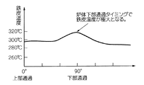
(iv)図9は、鉄皮9の円周方向についての温度変化サイクルを示すグラフである。同図にグラフで示すように、回転炉1の炉底部付近には溶融金属が溜まり、鉄皮9の表面の同じ部位でも円周方向の下部を通過するタイミングで鉄皮9の温度が最も上昇するため、炉体2の下部における耐火物損耗部分の保護を強化する必要がある。
(Iii) When the temperature of the
(Iv) FIG. 9 is a graph showing a temperature change cycle in the circumferential direction of the
そこで、本実施の形態では、これらの不具合(i)〜(iv)の発生を未然に防止するために、鉄皮9への冷却水供給量を調整するという第2の工程を初めとして、以下の手段(2)〜(5)を採用する。
Therefore, in the present embodiment, in order to prevent the occurrence of these problems (i) to (iv), the second step of adjusting the cooling water supply amount to the
(2)第2の工程(鉄皮への冷却水供給量の調整)
本実施の形態では、回転炉1の鉄皮9の温度を測定することにより検出及び特定された炉体2の耐火物8の損耗部の損耗の度合いに応じて、この損耗部を部分的に適切に冷却することにより、回転炉1の耐火物8の損耗、さらには耐火物8の損耗に起因した鉄皮9の溶損を効果的に抑制してその延命を図る。
(2) Second step (adjustment of the amount of cooling water supplied to the iron skin)
In the present embodiment, the worn portion is partially determined according to the degree of wear of the worn portion of the refractory 8 of the
具体的には、本実施の形態では、耐火物8の局部損耗を検知するため、後述する図11及び図12に示すように、回転炉1の炉体2の周囲に、炉体長手方向の温度分布を測定するための放射温度計12を設置してある。この放射温度計12と炉体2の回転とによって、炉体2の円周方向の温度分布を測定する。そして、放射温度計12により測定した鉄皮9の温度が、400℃を超える過熱部が存在すると、超えた温度上昇分に応じた量の冷却水14を長手方向位置に対応した冷却水供給部13から個別に供給する。これにより、炉体長手方向について測定した温度が予め定めた管理温度域を逸脱した部位に対して、炉体長手方向に配置した複数の冷却水供給部13それぞれから鉄皮9の外面に供給される冷却水14の量を、複数の冷却水供給部13それぞれ毎に個別に調整する。
Specifically, in this embodiment, in order to detect local wear of the refractory 8, as shown in FIGS. 11 and 12 to be described later, around the
一方、炉体円周方向についても、炉体長手方向と同様に冷却水供給部13を複数台円周状に配列することが最も適切であると考えられるが、本実施の形態では簡易性を重視して、炉体円周方向については、回転炉1の炉体の上方に一台設置してある。そして、放射温度計12で測定した温度データを回転に同期させて円周方向にトラッキングしておくことにより、炉体円周方向について測定した温度が予め定めた管理温度域を逸脱した部位が鉄皮9の外面に冷却水14を供給する冷却水供給部13を通過する時に、その温度データの温度上昇分に応じた所望の量の冷却水14を供給する。これにより、過熱部が冷却水供給部13の付近を通過したタイミングでのみ所望の量の冷却水を供給することができる。
On the other hand, with respect to the circumferential direction of the furnace body, it is considered most appropriate to arrange a plurality of cooling
本実施の形態では、このように鉄皮9への冷却水供給量を調整することから、鉄皮9の過熱の程度に応じて適した量の冷却水14を供給でき、鉄皮9の温度が比較的低い耐火物の非損耗部を過剰に冷却することはなくなり、この耐火物に損傷を発生させる恐れがなくなる。本実施の形態では、このようにして、上述した不具合1が解決される。
In this embodiment, since the amount of cooling water supplied to the
さらに、本実施の形態では、以下に説明する第3の工程〜第5の工程も、第1の工程及び第2の工程とともに行うことにより、鉄皮9の保護を万全に行う。そこで、第3の工程〜第5の工程を順次説明する。
Furthermore, in this Embodiment, the 3rd process-the 5th process demonstrated below are also performed with a 1st process and a 2nd process, and the protection of the
(3)第3の工程(冷却後における所定時間の冷却水の供給停止又は供給量の減少)
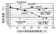
図10は、本実施の形態における冷却水供給方法の一例を経時的に例示するグラフである。
(3) Third step (stopping the cooling water supply for a predetermined time after cooling or reducing the supply amount)
FIG. 10 is a graph illustrating an example of the cooling water supply method according to the present embodiment over time.
図10にグラフで示すように、本実施の形態では、第2の工程により、鉄皮9の温度の測定結果により炉体2の過熱部のみに対して、炉体長手方向及び/又は炉体円周方向に部分的に冷却水14を供給した後に、所定時間だけ冷却水14の供給を停止するか、又は冷却水14の供給量を減少することにより、鉄皮9の温度の上昇経過を監視し、温度上昇部位の再検出を行う。
As shown in the graph of FIG. 10, in the present embodiment, in the second step, the furnace body longitudinal direction and / or the furnace body with respect to only the superheated portion of the
すなわち、本実施の形態の方法によって鉄皮9の過熱部に冷却水14を継続して供給すると、鉄皮9の温度は次第に低下して最終的に鉄皮9の上限管理温度である400℃を下回り、鉄皮9の表面の温度分布が耐火物の損耗の程度に関係なく略一様となる。しかし、この状態が継続すると、耐火物の損耗部位を温度の高低によって検出することができなくなることや、炉体全体の温度が低下してしまう等の問題がある。
That is, when the cooling
そこで、本実施の形態では、耐火物8の損耗の度合いに応じて冷却水供給量を変更する。例えば、冷却水14の供給を停止した場合における鉄皮9の温度の下限管理値を所定の温度(例えば200℃)として定め、この値を下回る場合には、耐火物8の損耗レベルが小さいか又は損耗が無いものとみなして、冷却水14の供給を減らすか又は停止する等の調整を行うことによって、温度上昇の傾向から損耗部を常時把握しながら、耐火物8が適正に冷却されるように調整する。
Therefore, in the present embodiment, the cooling water supply amount is changed according to the degree of wear of the refractory 8. For example, when the supply of the cooling
本実施の形態では、耐火物8の厚さが正常な200mm以上400mm以下である場合、炉内温度が1300℃付近の溶融操業で鉄皮9の表面温度が所定温度(図7で200℃)以下となり得ることから、鉄皮9の温度の下限管理値を200℃と定めた。
In the present embodiment, when the thickness of the refractory 8 is normal 200 mm or more and 400 mm or less, the surface temperature of the
また、本実施の形態では、第2の工程により、耐火物8の厚さが正常な部位が冷却水供給部を通過するタイミングで、冷却水14の供給を一時的に停止させて耐火物8の過剰冷却を抑制するが、耐火物8の厚さが正常であることの判断は、耐火物8の厚みが正常な範囲(200mm以上400mm以下)の回転炉1で炉内温度1300℃で操業すると鉄皮9の温度は200℃付近となることから、鉄皮9の温度の測定結果に基づいて判断することができる。
これにより、冷却水14を常時供給しないため、耐火物損耗部を検出することができる。このため、上述した不具合2を解決することができる。
In the present embodiment, in the second step, the supply of the cooling
Thereby, since the cooling
(4)第4の工程(鉄皮温度測定及びトラッキング制御)
図11は、本実施の形態における鉄皮温度測定及びトラッキング制御方法の一例を示す模式的説明図である。図11に示すように、温度測定を行う放射温度計12を、回転する炉体2を介して冷却水供給部13とは反対側に配置し、冷却水14がかからない部分で測定したデータ(温度・周方向位置情報)を回転に同期させて冷却水供給部13までトラッキングさせて、冷却水供給部13で損耗度に応じた適正な量の冷却水14を供給する。
(4) Fourth step (iron skin temperature measurement and tracking control)
FIG. 11 is a schematic explanatory view showing an example of the iron skin temperature measurement and tracking control method in the present embodiment. As shown in FIG. 11, the
また、本実施の形態では、鉄皮の温度測定は簡易的な方法として放射温度計を用いて行ったが、供給された冷却水が測定点に入ると鉄皮の温度を正確に測定できなくなるため、鉄皮の表面上で冷却水がかからない部位を放射温度計の測定点として配置した。 In this embodiment, the temperature measurement of the iron skin was performed using a radiation thermometer as a simple method. However, when the supplied cooling water enters the measurement point, the temperature of the iron skin cannot be measured accurately. Therefore, the part where the cooling water is not applied on the surface of the iron skin was arranged as a measurement point of the radiation thermometer.
これにより、測定点に冷却水がかかることに起因した、鉄皮9の温度の測定誤差を生じることはない。これにより、上述した不具合3を解決することができる。
Thereby, the measurement error of the temperature of the
(5)第5の工程(炉体下部を通過するタイミングでの炉体2の回転速度の調節)
図12は、本実施の形態における炉体下部通過時の保護操作の一例を示す模式的説明図である。図12に示すように、冷却水14がかからない部分で測定したデータ(温度・周方向位置情報)を回転に同期させて冷却水供給部13までトラッキングさせたトラッキングデータを用いて、損耗部が炉体下部を通過するタイミングで炉体2の回転速度を調節することにより、耐火物損耗部が高温部に曝される時間を相対的に短縮し、これにより、損耗の局部進行を抑えることができる。
(5) Fifth step (adjustment of the rotational speed of the
FIG. 12 is a schematic explanatory view showing an example of a protection operation when passing through the lower part of the furnace body in the present embodiment. As shown in FIG. 12, using the tracking data obtained by tracking the data (temperature / circumferential position information) measured at a portion not exposed to the cooling
すなわち、溶融金属が溜まる回転炉1の底部は、炉体円周方向の中でも特に高温となる部位である。そこで、この位置を通過するタイミングでは、他の部位を通過するタイミングと比較して耐火物8の内壁温度が特に上昇するとともに、冷却水14は炉体上部から供給されるために炉体下部の冷却効果が低下するという問題がある。
That is, the bottom of the
そこで、本実施の形態では、耐火物8が損耗した鉄皮9の過熱部が溶融金属に直接曝される可能性のある炉体下部垂線に対して±30°以内の範囲に入っている際には、通常20分サイクルで回転する回転炉1を10分サイクル以上で回転するように調節し、損耗部が高温となるこの範囲を通過する時間を非損耗部位の50%以下に短縮させることにより、局部損耗の進行を抑える。
Therefore, in the present embodiment, when the superheated portion of the
これにより、炉体2の下部における耐火物損耗部分の保護を強化することができ、上述した不具合4を解決することができる。
このように、本実施の形態によれば、工程1及び工程2を経て、さらに工程3〜工程5を行うことによって、逸脱した部位の温度を管理温度域内とすることができる。このため、回転炉1の耐火物の損耗を効果的に抑制することができ、回転炉の鉄皮を保護することができる。これにより、従来は1ヶ月程度であった補修周期を例えば約6ヶ月程度にまで大幅に延長できることによって保守コストの抑制や稼働率の改善等を図ることができる。
Thereby, protection of the refractory worn part in the lower part of the
Thus, according to this Embodiment, the temperature of the site | part which deviated can be made into a management temperature range by performing the process 3-the
さらに、本発明を実施例を参照しながら説明する。
以降の各実施例では、全長14m、直径5m、処理能力2500乾燥トン/月、回転周期20分の並行流式ロータリーキルンを用いた。処理原料は、石炭、廃プラスチック及び酸化鉄を含む製鉄ダストである。この並行流式ロータリーキルンの炉内温度は1300℃以上の高温であり、耐火物の損耗が無い場合(厚み363mm)でも、鉄皮の表面温度は200℃以上に達する。
Furthermore, the present invention will be described with reference to examples.
In the following examples, a parallel flow rotary kiln having a total length of 14 m, a diameter of 5 m, a processing capacity of 2500 tons / month, and a rotation period of 20 minutes was used. A processing raw material is iron-making dust containing coal, waste plastic, and iron oxide. The furnace temperature of the parallel flow rotary kiln is as high as 1300 ° C. or higher, and even when there is no refractory wear (thickness 363 mm), the surface temperature of the iron skin reaches 200 ° C. or higher.
図13は、鉄皮の温度測定を行わない従来法と、本発明法とを比較して示すグラフである。
図13のグラフにおける曲線Aは冷却を行わない場合の鉄皮の温度分布を示し、曲線Bは従来法の長手方向に一定量の冷却水を供給した場合の鉄皮の温度分布を示し、さらに曲線Cは鉄皮の温度が400℃以上となる点のみ冷却水を供給した場合の鉄皮の温度分布を示す。なお、鉄皮の温度は放射温度計を用いて炉体円周方向に対して真横から測定したものである。
FIG. 13 is a graph showing a comparison between the conventional method in which the temperature measurement of the iron skin is not performed and the method of the present invention.
A curve A in the graph of FIG. 13 shows the temperature distribution of the iron skin when cooling is not performed, and a curve B shows the temperature distribution of the iron skin when a certain amount of cooling water is supplied in the longitudinal direction of the conventional method. Curve C shows the temperature distribution of the iron skin when the cooling water is supplied only at the point where the temperature of the iron skin is 400 ° C. or higher. Note that the temperature of the iron skin was measured from the side of the furnace body circumferential direction using a radiation thermometer.
図13のグラフにおける曲線Aから、バーナの炎先端付近で炉内温度が高くなるため、この付近で鉄皮の温度がピーク(400℃付近)に達したことがわかる。
また曲線Bから、バーナの炎先端付近の温度が300℃付近にまで低減されるが、その他の部分(出側付近及び入側付近等)では、150℃以下にまで過剰に冷却されたことが分かる。
From the curve A in the graph of FIG. 13, it can be seen that the temperature in the furnace reached a peak (around 400 ° C.) near the flame tip of the burner because the temperature inside the furnace became high.
Also, from curve B, the temperature near the flame tip of the burner is reduced to around 300 ° C, but in other parts (near the exit side and near the entrance side, etc.), it was overcooled to 150 ° C or less. I understand.
これに対して、曲線Cから、鉄皮の温度が200〜300℃の範囲となり、過剰な冷却を抑制しながら鉄皮の高温部を確実に冷却でき、炉内温度分布の偏差による局部的な損耗に対して有効であることがわかる。 On the other hand, from the curve C, the temperature of the iron skin is in the range of 200 to 300 ° C., the high temperature portion of the iron skin can be reliably cooled while suppressing excessive cooling, and the local temperature due to the deviation of the temperature distribution in the furnace It can be seen that it is effective against wear.
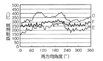
図14は、炉体円周の真横から測定した炉体円周方向の温度分布を示すグラフである。図14に示すグラフにおいて、曲線Dは冷却を行わない従来法による場合を示し、曲線Eは温度測定を行わずに一定の冷却水を供給する従来法による場合を示し、曲線Fは鉄皮の温度が300℃以上となる点のみ冷却水を供給した本発明法による場合を示す。 FIG. 14 is a graph showing the temperature distribution in the furnace body circumferential direction measured from right next to the furnace body circumference. In the graph shown in FIG. 14, curve D shows the case of the conventional method in which cooling is not performed, curve E shows the case of the conventional method in which constant cooling water is supplied without performing temperature measurement, and curve F shows the iron skin. The case according to the method of the present invention in which the cooling water is supplied only at the point where the temperature is 300 ° C. or higher is shown.
実施例1と同様に、曲線Dは局部的に鉄皮の温度が300℃を超える点がある。これは耐火物の損粍によるものと考えられる。
また、曲線Eの場合は局部損耗部と健全部位の区別なく常時一定量の冷却水を供給するために、300℃を超える鉄皮の過熱部は解消されるものの、健全部の温度は200℃以下にまで過剰に冷却されたことがわかる。
Similar to Example 1, curve D has a point where the temperature of the iron skin locally exceeds 300 ° C. This is thought to be due to damage to the refractory.
Further, in the case of curve E, in order to always supply a constant amount of cooling water without distinguishing between the locally worn part and the healthy part, the overheated part of the iron skin exceeding 300 ° C. is eliminated, but the temperature of the healthy part is 200 ° C. It turns out that it cooled too much to the following.
これに対し、曲線Fでは、鉄皮の温度が200〜300℃の範囲となり、局部的な温度上昇部位が目立たなくなることがわかる。 On the other hand, in the curve F, it can be seen that the temperature of the iron skin is in the range of 200 to 300 ° C., and the local temperature rise portion becomes inconspicuous.
図15は、耐火物の局部損耗部がある炉を300時間運転し、一定量の冷却水を供給する比較例、実施例1、実施例2及び、実施例1と実施例2とをともに行った場合の4種について、ある1箇所の損耗部における鉄皮の温度が上限管理値である400℃を超えた場合、および下限管理値である200℃を割り込んだ場合のそれぞれについて、その全運転時間に対する外れた時間の割合を比較して示すグラフである。 FIG. 15 shows a comparative example in which a furnace with a local wear part of a refractory is operated for 300 hours and supplying a certain amount of cooling water, Example 1 and Example 2, and Example 1 and Example 2 together. In the case where the temperature of the iron shell at a certain worn part exceeds 400 ° C, which is the upper limit control value, and when 200 ° C, which is the lower limit control value, is interrupted, It is a graph which compares and shows the ratio of the time which went out with respect to time.
図15に示すグラフから、本発明にしたがって炉体長手方向又は炉体円周方向の温度管理をすることにより、鉄皮の温度が管理温度の上限値及び下限値から外れる割合が抑えられることが分かる。 From the graph shown in FIG. 15, by controlling the temperature in the longitudinal direction of the furnace body or in the circumferential direction of the furnace body according to the present invention, the rate at which the temperature of the iron shell deviates from the upper limit value and the lower limit value of the management temperature can be suppressed. I understand.
さらに、炉体長手方向及び炉体円周方向の温度管理を併用することにより、管理温度の上限値及び下限値からの外れは、実用上解消されることがわかる。 Furthermore, it turns out that the deviation from the upper limit value and the lower limit value of the management temperature is practically eliminated by using the temperature management in the furnace body longitudinal direction and the furnace body circumferential direction in combination.
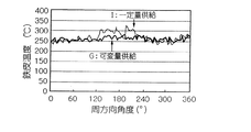
図16は、冷却水量を一定として鉄皮の温度管理値を超えた部分のみに冷却水を供給した場合(曲線G)と、温度実績に応じて適正な冷却水量を可変として供給した場合(曲線I)とを比較して示すグラフである。 FIG. 16 shows a case where the cooling water amount is constant and the cooling water is supplied only to a portion exceeding the temperature control value of the iron shell (curve G), and an appropriate amount of cooling water is supplied as a variable according to the actual temperature (curve). It is a graph which compares and shows I).
図16に示すグラフから、温度実績に応じて適正な冷却水量を可変として供給すれば、鉄皮の表面の温度分布の偏差を小さくすることができ、耐火物の局部損耗を抑制することができることがわかる。 From the graph shown in FIG. 16, if an appropriate amount of cooling water is supplied as a variable according to the temperature results, the deviation of the temperature distribution on the surface of the iron skin can be reduced, and local wear of the refractory can be suppressed. I understand.
図17は、冷却水の供給パターンの違いに基づく鉄皮の温度の変化を示すグラフである。
図17に示すグラフにおいて、曲線Jは冷却水を常時供給しながら鉄皮の温度測定を行った場合を示し、曲線Kは一定周期毎に冷却水の供給を停止して鉄皮の温度測定を行った場合を示す。なお、図17に示すグラフの結果は、同じ耐火物損耗部の鉄皮の温度分布を比較したものであり、鉄皮の温度は炉体側面から放射温度計を用いて測定している。
FIG. 17 is a graph showing changes in the temperature of the iron skin based on the difference in the cooling water supply pattern.
In the graph shown in FIG. 17, curve J shows the case where the temperature of the iron skin is measured while constantly supplying cooling water, and curve K shows the temperature measurement of the iron skin by stopping the supply of cooling water at regular intervals. The case where it went is shown. In addition, the result of the graph shown in FIG. 17 compares the temperature distribution of the iron skin of the same refractory wear part, and the temperature of the iron skin is measured using the radiation thermometer from the furnace body side surface.
曲線Jに示すように、冷却水を常時供給しながら鉄皮の温度測定を行うと、継続的な冷却効果により損耗部位の鉄皮温度が上昇しなくなるため、損耗部位であることが判らなくなってしまう。 As shown in curve J, when the temperature of the iron skin is measured while constantly supplying cooling water, the iron temperature of the worn portion does not increase due to the continuous cooling effect, so that it is not known that the portion is a worn portion. End up.
これに対して、曲線Kに示すように、一定周期毎に冷却水の供給を停止すると冷却効果が一時的に無くなるため、正確な温度測定ができ、過不足のない適切な冷却水の供給を行うことができる。 On the other hand, as shown by the curve K, if the cooling water supply is stopped at regular intervals, the cooling effect is temporarily lost. Therefore, accurate temperature measurement can be performed, and appropriate cooling water supply without excess or deficiency can be performed. It can be carried out.
図18は、耐火物損耗部が炉体円周方向の各部を通過するタイミングにおける、鉄皮の温度測定結果を示すグラフであり、図18における曲線Kは炉体回転速度を(1/20)rpmで一定とした場合を示し、曲線Mは耐火物損耗部が炉体下部が通過するタイミングでのみ炉体回転速度を(1/20)rpmから(1/10)rpmに速度調整した場合を示す。 FIG. 18 is a graph showing the temperature measurement result of the iron shell at the timing when the refractory worn part passes through each part in the circumferential direction of the furnace body, and the curve K in FIG. 18 represents the furnace body rotational speed (1/20). The curve M shows the case where the furnace body rotation speed is adjusted from (1/20) rpm to (1/10) rpm only at the timing when the refractory wear part passes through the lower part of the furnace body. Show.
図18にグラフで示すように、炉体下部を通過するタイミングでは明らかに鉄皮温度が上昇しており(曲線L)、炉内部が高温に曝されていることがわかる。
これに対し、耐火物損耗部が炉体下部が通過するタイミングでのみ炉体回転速度を(1/20)rpmから(1/10)rpmに速度調整を行うと、曲線Mに示すように、耐火物損耗部の鉄皮の温度上昇が緩和され、耐火物を高温から保護できることがわかる。
As shown in the graph of FIG. 18, at the timing of passing through the lower part of the furnace body, the iron skin temperature clearly rises (curve L), and it can be seen that the interior of the furnace is exposed to a high temperature.
On the other hand, if the furnace rotation speed is adjusted from (1/20) rpm to (1/10) rpm only at the timing when the refractory wear part passes through the lower part of the furnace body, as shown in the curve M, It can be seen that the increase in the temperature of the iron skin of the refractory wear part is mitigated and the refractory can be protected from high temperatures.
図19は、耐火物の局部損耗部が存在する炉を300時間運転し、各実施例についてある1箇所の損耗部における鉄皮の温度が上限管理値である400℃を超えた場合、及び下限管理値である200℃を割り込んだ場合のそれぞれについて、その全運転時間に対する外れた時間の割合と耐火物寿命との関係を示すグラフである。 FIG. 19 shows a case where a furnace in which a local wear part of a refractory is present is operated for 300 hours, and the temperature of the iron shell at one wear part in each example exceeds 400 ° C., which is the upper limit control value, and the lower limit. It is a graph which shows the relationship between the ratio of the time which went out with respect to the total operation time, and the refractory life about each when 200 degreeC which is a management value is interrupted.
図19に示すグラフから、従来法によると耐火物の補修周期が1ヶ月間程度の頻度を要していたのに対し、本発明によれば、これを約6ヶ月間程度にまで延長することが可能となった。 From the graph shown in FIG. 19, according to the present invention, the repair period of the refractory required a frequency of about one month according to the conventional method, but according to the present invention, this is extended to about six months. Became possible.
Claims (8)
Priority Applications (1)
| Application Number | Priority Date | Filing Date | Title |
|---|---|---|---|
| JP2004004527A JP4380331B2 (en) | 2004-01-09 | 2004-01-09 | How to protect the iron core of a rotary furnace |
Applications Claiming Priority (1)
| Application Number | Priority Date | Filing Date | Title |
|---|---|---|---|
| JP2004004527A JP4380331B2 (en) | 2004-01-09 | 2004-01-09 | How to protect the iron core of a rotary furnace |
Publications (2)
| Publication Number | Publication Date |
|---|---|
| JP2005195306A JP2005195306A (en) | 2005-07-21 |
| JP4380331B2 true JP4380331B2 (en) | 2009-12-09 |
Family
ID=34819122
Family Applications (1)
| Application Number | Title | Priority Date | Filing Date |
|---|---|---|---|
| JP2004004527A Expired - Fee Related JP4380331B2 (en) | 2004-01-09 | 2004-01-09 | How to protect the iron core of a rotary furnace |
Country Status (1)
| Country | Link |
|---|---|
| JP (1) | JP4380331B2 (en) |
Families Citing this family (6)
| Publication number | Priority date | Publication date | Assignee | Title |
|---|---|---|---|---|
| JP5428864B2 (en) * | 2010-01-05 | 2014-02-26 | 宇部興産株式会社 | Cement manufacturing apparatus and cooling method of cement manufacturing apparatus |
| JP5585104B2 (en) * | 2010-02-05 | 2014-09-10 | 宇部興産株式会社 | Cooling apparatus and cooling method for rotary kiln |
| JP6103430B2 (en) * | 2013-03-22 | 2017-03-29 | 宇部興産株式会社 | Rotary kiln axial center correction device and rotary kiln axial center correction method |
| JP2014043391A (en) * | 2013-10-18 | 2014-03-13 | Ube Ind Ltd | Cement production apparatus and cooling method thereof |
| WO2021050742A1 (en) * | 2019-09-11 | 2021-03-18 | Quantum IR Technologies, LLC | Rotary kiln preheater thermal monitoring systems |
| US12352499B2 (en) | 2019-09-11 | 2025-07-08 | Quantum IR Technologies, LLC | Rotary kiln brick layer thermal monitoring systems |
-
2004
- 2004-01-09 JP JP2004004527A patent/JP4380331B2/en not_active Expired - Fee Related
Also Published As
| Publication number | Publication date |
|---|---|
| JP2005195306A (en) | 2005-07-21 |
Similar Documents
| Publication | Publication Date | Title |
|---|---|---|
| US3849587A (en) | Cooling devices for protecting refractory linings of furnaces | |
| US8585961B2 (en) | Preheaters for preheating steelmaking ladles | |
| JP4380331B2 (en) | How to protect the iron core of a rotary furnace | |
| US20090193645A1 (en) | Method for continuous casting and rolling at increased casting speed followed by hot rolling of relatively thin metal strands, especially steel strands, and a continuous casting and rolling installation | |
| TWI642788B (en) | Cooling plate for furnace body protection | |
| JP4998045B2 (en) | Rotary kiln type high temperature processing equipment | |
| JP5111473B2 (en) | Water cooling jacket, furnace body cooling structure and furnace body cooling method using the same | |
| US20120018122A1 (en) | Furnace and a Method for Cooling a Furnace | |
| JP7846339B2 (en) | Hearth tapping method | |
| JP2007077440A (en) | Method for operating blast furnace under condition of blowing-stop with reduced molten iron level | |
| JP4056534B2 (en) | Furnace bottom temperature measuring method and apparatus, and melting furnace bottom monitoring method and apparatus | |
| JP6466827B2 (en) | Reduced iron production equipment | |
| JP2001335818A (en) | Blast furnace bottom cooling method | |
| JP4132128B2 (en) | Blast furnace operation method | |
| JP2021131222A (en) | Method for detecting material charge pipe clogging, method for dissolving material charge pipe clogging, and melting facility | |
| EP3894602B1 (en) | Method for protecting an inner wall of a shaft furnace | |
| JP5972243B2 (en) | Judgment method of the iron skin structure at the exit of the rotary kiln and the repair time of the iron skin | |
| JPS6137327B2 (en) | ||
| JPH09296205A (en) | Cooling plate for blast furnace wall | |
| JP3512042B2 (en) | Cooling method of blast furnace refractory | |
| KR20250034906A (en) | Blower for metallurgical furnace | |
| JP4038153B2 (en) | Blast furnace bottom cooling method | |
| JPH11323425A (en) | Water-cooled molten metal container | |
| Schmidt | Precise Control of the Kiln Shell Temperature Versus Conventional Cooling Fans | |
| JP3889847B2 (en) | Blast furnace bottom cooling method |
Legal Events
| Date | Code | Title | Description |
|---|---|---|---|
| A621 | Written request for application examination |
Free format text: JAPANESE INTERMEDIATE CODE: A621 Effective date: 20060216 |
|
| A977 | Report on retrieval |
Free format text: JAPANESE INTERMEDIATE CODE: A971007 Effective date: 20080423 |
|
| A131 | Notification of reasons for refusal |
Free format text: JAPANESE INTERMEDIATE CODE: A131 Effective date: 20080507 |
|
| A521 | Written amendment |
Free format text: JAPANESE INTERMEDIATE CODE: A523 Effective date: 20080704 |
|
| A131 | Notification of reasons for refusal |
Free format text: JAPANESE INTERMEDIATE CODE: A131 Effective date: 20090623 |
|
| A521 | Written amendment |
Free format text: JAPANESE INTERMEDIATE CODE: A523 Effective date: 20090803 |
|
| TRDD | Decision of grant or rejection written | ||
| A01 | Written decision to grant a patent or to grant a registration (utility model) |
Free format text: JAPANESE INTERMEDIATE CODE: A01 Effective date: 20090901 |
|
| A01 | Written decision to grant a patent or to grant a registration (utility model) |
Free format text: JAPANESE INTERMEDIATE CODE: A01 |
|
| A61 | First payment of annual fees (during grant procedure) |
Free format text: JAPANESE INTERMEDIATE CODE: A61 Effective date: 20090914 |
|
| FPAY | Renewal fee payment (event date is renewal date of database) |
Free format text: PAYMENT UNTIL: 20121002 Year of fee payment: 3 |
|
| R150 | Certificate of patent or registration of utility model |
Free format text: JAPANESE INTERMEDIATE CODE: R150 |
|
| FPAY | Renewal fee payment (event date is renewal date of database) |
Free format text: PAYMENT UNTIL: 20131002 Year of fee payment: 4 |
|
| FPAY | Renewal fee payment (event date is renewal date of database) |
Free format text: PAYMENT UNTIL: 20131002 Year of fee payment: 4 |
|
| S111 | Request for change of ownership or part of ownership |
Free format text: JAPANESE INTERMEDIATE CODE: R313111 |
|
| FPAY | Renewal fee payment (event date is renewal date of database) |
Free format text: PAYMENT UNTIL: 20131002 Year of fee payment: 4 |
|
| R350 | Written notification of registration of transfer |
Free format text: JAPANESE INTERMEDIATE CODE: R350 |
|
| LAPS | Cancellation because of no payment of annual fees |