JP4380452B2 - Pile construction method and wall pile provided with a nodal extension constructed by the method - Google Patents
Pile construction method and wall pile provided with a nodal extension constructed by the method Download PDFInfo
- Publication number
- JP4380452B2 JP4380452B2 JP2004224142A JP2004224142A JP4380452B2 JP 4380452 B2 JP4380452 B2 JP 4380452B2 JP 2004224142 A JP2004224142 A JP 2004224142A JP 2004224142 A JP2004224142 A JP 2004224142A JP 4380452 B2 JP4380452 B2 JP 4380452B2
- Authority
- JP
- Japan
- Prior art keywords
- pile
- bucket
- excavation hole
- kelly bar
- wall
- Prior art date
- Legal status (The legal status is an assumption and is not a legal conclusion. Google has not performed a legal analysis and makes no representation as to the accuracy of the status listed.)
- Expired - Fee Related
Links
- 238000010276 construction Methods 0.000 title claims description 14
- 238000000034 method Methods 0.000 title description 10
- 238000009412 basement excavation Methods 0.000 claims description 39
- 238000005553 drilling Methods 0.000 claims description 3
- 239000003381 stabilizer Substances 0.000 description 16
- 238000012986 modification Methods 0.000 description 8
- 230000004048 modification Effects 0.000 description 8
- 238000010586 diagram Methods 0.000 description 2
- 238000009751 slip forming Methods 0.000 description 2
- 230000000694 effects Effects 0.000 description 1
- 238000005259 measurement Methods 0.000 description 1
- 230000003014 reinforcing effect Effects 0.000 description 1
- 230000000087 stabilizing effect Effects 0.000 description 1
Images


Landscapes
- Piles And Underground Anchors (AREA)
- Placing Or Removing Of Piles Or Sheet Piles, Or Accessories Thereof (AREA)
Description
本発明は、壁杭施工方法およびその方法により施工された杭に関し、特に、節状の拡張部が形成された杭を施工できる壁杭施工方法およびその方法により施工された杭に関する。 The present invention relates to a wall pile construction method and a pile constructed by the method, and more particularly to a wall pile construction method capable of constructing a pile in which a node-like extension portion is formed and a pile constructed by the method.
従来、建物の押込力および地震等の引抜力に対応するために、節状の拡張部である拡径部が外周に亘って形成された丸杭が用いられている。この拡径部を有する丸杭は、例えば、特許文献1に示すように、ブームの先端から鉛直下方へと延びて、この鉛直方向を軸として回転するケリーバーと、このケリーバーの先端に取り付けられ、前記ケリーバーの回転に伴って回転して地盤を掘削するとともに、径方向に開閉自在に取り付けられたバケットとを備える回転式掘削装置を用いて、予め地盤に形成した掘削孔に、閉じた状態のバケットを挿入した後、バケットを開きつつケリーバーを回転(正転)させることにより施工される。
Conventionally, in order to cope with a pushing force of a building and a pulling-out force such as an earthquake, a round pile in which an enlarged diameter portion which is a node-like extended portion is formed over the outer periphery is used. For example, as shown in
ところで、例えば、隣地との間に十分な距離を確保できない場合等には、片面側のみに拡幅部を有する壁杭も施工される。このような壁杭は、例えば、特許文献1に示す掘削装置を利用して、回転中心となるケリーバーの位置を大きく偏心させて、壁杭の片面側のみを掘削するようにすることにより、掘削孔の内壁面のうちの片面側にのみ拡張部用の掘削孔(拡張空間)を形成し、その後、掘削孔にコンクリートを打設して施工される。
By the way, for example, when a sufficient distance cannot be ensured between the adjacent land, a wall pile having a widened portion only on one side is also constructed. Such a wall pile is excavated by excavating only one side of the wall pile by using the excavator shown in
しかしながら、ケリーバーの位置を偏心させて壁杭の片面側に拡張空間を形成する方法では、ケリーバーやバケットを挿入する前記掘削孔の幅寸法が小さい場合、すなわち、壁厚の小さな壁杭を施工する場合には、ケリーバーの偏心の程度を小さくせざるを得ず、このため、壁杭の両面側に亘って拡張空間が形成されてしまい、片面側のみに拡張部が形成された壁杭を形成することができない。なお、このような問題は、前記した壁杭に限らず、一部側に節状の拡張部を有する丸杭を施工する場合においても、同様に発生する。 However, in the method of forming the expansion space on one side of the wall pile by decentering the position of the kelly bar, if the width dimension of the drilling hole into which the kelly bar or bucket is inserted is small, that is, the wall pile having a small wall thickness is constructed. In this case, the degree of eccentricity of the Kelly bar has to be reduced, so that an expansion space is formed over both sides of the wall pile, and a wall pile with an extension portion formed only on one side is formed. Can not do it. Such a problem occurs not only in the above-described wall pile but also in the case of constructing a round pile having a node-like extended portion on a part thereof.
本発明の目的は、径や幅の小さい杭においても、一部側に節状の拡張部が形成された杭を施工することができる杭施工方法およびその方法により施工された節状の拡張部を備える壁杭を提供することにある。 An object of the present invention, the diameter even and width small piles, part side section shaped extension portion extended nodular construction by pile construction methods and method is Ru can be applying a formed pile It is providing the wall pile provided with a part.
本発明は、鉛直方向を軸として回転するケリーバーと、このケリーバーの先端に取り付けられ、前記ケリーバーの回転に伴って回転して地盤を掘削する径方向に開閉自在なバケットとを備える掘削装置を用いて、節状の拡張部が形成された杭を施工するための杭施工方法であって、予め形成された掘削孔に、閉じた状態の前記バケットを挿入する工程と、前記バケットを開きながら、前記ケリーバーを所定の角度範囲で正回転および逆回転を繰り返して、前記バケットで前記掘削孔の内壁面の一部を掘削することにより、前記節状の拡張部に対応する拡張空間を形成する工程と、前記掘削孔の中にコンクリートを打設して、前記節状の拡張部が形成された杭を形成する工程とを備えることを特徴とする。ここで、前記拡張部が形成された杭としては、一部側に拡径部が形成された丸杭や、片面側のみに節状の拡幅部が形成された壁杭等が含まれ、この壁杭には、壁面に沿って拡幅部が連続して形成された壁杭も含まれる。 The present invention uses a drilling device including a kerry bar that rotates about a vertical direction and a bucket that is attached to the tip of the kelly bar and that can be opened and closed in a radial direction to rotate with the rotation of the kelly bar and excavate the ground. A pile construction method for constructing a pile in which a node-shaped extension portion is formed, the step of inserting the bucket in a closed state into a pre-formed excavation hole, while opening the bucket, A step of forming an expansion space corresponding to the knot-like expansion portion by excavating a part of the inner wall surface of the excavation hole with the bucket by repeating forward rotation and reverse rotation of the kelly bar within a predetermined angle range. And a step of placing concrete in the excavation hole to form a pile in which the node-shaped expansion portion is formed. Here, the pile formed with the extended portion includes a round pile formed with a diameter enlarged portion on one side, a wall pile formed with a node-like widened portion only on one side, and the like. The wall pile includes a wall pile in which the widened portion is continuously formed along the wall surface.
本発明によれば、ケリーバーを所定の角度範囲で正回転および逆回転することにより、バケットが前記角度範囲で正転、逆転するため、掘削孔の内壁面の一部側のみを確実に掘削できる。このため、仮に、掘削孔の径が小さい場合や、掘削孔が略楕円形状で、その厚み方向の寸法が小さい場合であっても、一部側に節状の拡張部が形成された杭を確実に施工することができる。 According to the present invention, by rotating the kelly bar forward and backward within a predetermined angle range, the bucket rotates forward and reverse within the angle range, so that only a part of the inner wall surface of the excavation hole can be reliably excavated. . For this reason, even if the diameter of the excavation hole is small, or the excavation hole is substantially elliptical and the dimension in the thickness direction is small, a pile with a nodal extension part formed on the part side is used. It can be reliably constructed.
本発明によれば、径や幅の小さい杭においても、一部側に節状の拡張部が形成された杭を施工することができるという効果がある。 According to the present invention, there is an effect that it is possible to construct a pile in which a node-like extended portion is formed on a part side even in a pile having a small diameter and width.
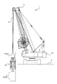
以下、本発明の一実施形態に係る杭施工方法に用いる掘削装置について、図面を参照して説明する。図1は、本実施形態に係る掘削装置1を模式的に示す側面図である。図1に示すように、掘削装置1は、地盤Gの上を走行する本体としての走行体12と、走行体12から上方へと延び、起伏旋回可能なブーム14と、ブーム14の先端から鉛直下方へと延びるケリーバー16と、ケリーバー16を回転させる回転装置(図示略)と、ケリーバー16の先端に取り付けられるバケット部20とを備えている。
Hereinafter, an excavator used for a pile construction method according to an embodiment of the present invention will be described with reference to the drawings. FIG. 1 is a side view schematically showing the
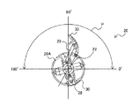
図2は、バケット部20を示す正面図である。また、図3は、バケット部20を示す横断面図である。前記回転装置は、鉛直方向を軸としてケリーバー16が一定の方向に連続的に回転(正転)する第1の状態と、図3の矢印Pに示すように、0°〜180°の範囲でケリーバー16が正転および逆転する第2の状態とを選択することができる。第2の状態を選択した場合には、例えば、前述した角度範囲の臨界点に達した際に、電流の方向を逆転させることにより、正転と逆転とを反転させることができる。
FIG. 2 is a front view showing the
図2,図3に示すように、バケット部20は、ケリーバー16(図1)の先端に取り付けられる油圧シリンダ22と、油圧シリンダ22に対して上下方向に進退するロッド24と、油圧シリンダ22およびロッド24を収容する収容ケース26とを備えている。また、バケット部20は、収容ケース26の開口26Aから突出可能に構成され、ロッド24の先端に取り付けられる例えば2本の腕部28と、収容ケース26に対して開閉自在に構成され、各腕部28の先端が取り付けられた例えば2枚のバケット30とを備えている。なお、図2は、図中右側のバケット30を閉じた状態を示している。また、腕部28は、例えば、ロッド24を軸として対称となる位置に配置することができ、この場合には、バケット30も収容ケース26に対して対称となる位置に配置される。
As shown in FIGS. 2 and 3, the
バケット30は、例えば、角度θ1,θ2がそれぞれ略45°の台形状に形成されている。台形の各辺には、地盤Gを効率良く掘削するための凹凸が形成されている。なお、バケット30の形状は、台形状に限らず、三角形状等の他の形状としてもよく、所望する拡張部の形状に応じて適宜変更すればよい。
For example, the
このようなバケット部20において、油圧シリンダ22からロッド24を図2中下方へと移動させると、ロッド24の先端に取り付けられた腕部28が収容ケース26の開口26Aから突出し、図3の実線で示すように、腕部28の先端に取り付けられたバケット30が収容ケース26の径方向へと開くことになる。一方、油圧シリンダ22側(図2中上方)へロッド24を移動させると、ロッド24の先端に取り付けられた腕部28が収容ケース26内に収容されて、図3の破線で示すように、腕部28の先端に取り付けられたバケット30が収容ケース26側へ閉じることになる。バケット部20は、ケリーバー16の回転に伴って回転し、開いた状態のバケット30により地盤を掘削できる。
In such a
図1に戻って、掘削装置1は、ケリーバー16とバケット部20との間に設けられ、ケリーバー16を水平方向に移動させるスタビライザー移動部40と、ケリーバー16が水平移動する際に、ケリーバー16の鉛直方向の姿勢を制御するケリーバー姿勢制御装置42とを備えている。ケリーバー姿勢制御装置42は、ケリーバー16の傾斜を測定する傾斜計44と、傾斜計44の測定結果に基づいて、走行体12の位置およびブーム14の姿勢を調整し、ケリーバー16が鉛直姿勢を制御する制御装置45とを備えている。
Returning to FIG. 1, the
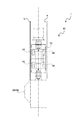
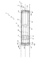
図4は、スタビライザー移動部40を側方から見た縦断面図である。図5は、スタビライザー移動部40を正面から見た縦断面図である。図6は、スタビライザー移動部40の横断面図である。図6に示すように、スタビライザー移動部40は、地盤Gに形成された、同図中左右方向に延びる長方形状の掘削孔A内に設けられている。スタビライザー移動部40は、掘削孔A内に設置される固定枠46(図6)と、固定枠46内に設けられる移動装置としての複数の油圧ジャッキ48と、固定枠46内に設けられるスタビライザー50とを備えている。
FIG. 4 is a longitudinal sectional view of the
各油圧ジャッキ48は、シリンダ52と、シリンダ52に対して掘削孔Aの長手方向(図6中の左右方向)に沿って水平に進退可能なロッド54とを備えている。
スタビライザー50は、水平方向に隣合うシリンダ52の間に取り付けられ、ケリーバー16を軸支する支持部材56と、シリンダ52の基端52Aに取り付けられる基端側部材58と、ロッド54の先端54Aに取り付けられる先端側部材60とを備えている。
Each
The
基端側部材58は、シリンダ52の基端52Aに固定された枠体62(図5)と、枠体62内に取り付けられ、ロッド54の進退方向と直交する方向(図6中の上下方向)に進退する油圧ジャッキ64とを備えている。同様に、先端側部材60は、ロッド54の先端54Aに固定された枠体63と、枠体63内に取り付けられた、ロッド54の進退方向と直交する方向(図6中の上下方向)に進退する油圧ジャッキ65とを備えている。油圧ジャッキ64,65は、夫々、シリンダ64A,65Aと、シリンダ64A,65Aに対して進退可能なロッド64B,65Bと、シリンダ64A,65Aの基端およびロッド64B,65Bの先端にそれぞれ取り付けられ、固定枠46に当接する当接部材64C,65Cとを備えている。
The base
このような油圧ジャッキ64,65によれば、シリンダ64A,65Aからロッド64B、65Bを突出させて、当接部材64C,65Cで固定枠46を介して掘削孔Aの内壁面を強く押圧することにより、基端側部材58および先端側部材60を掘削孔A内に固定できる。従って、基端側部材58及び先端側部材60の両方の油圧ジャッキ64,65のロッド64B,65Bを突出させることにより、スタビライザー移動部40を掘削孔Aの任意の高さ位置に保持できる。
According to such
また、油圧ジャッキ65のロッド65Bを突出させて先端側部材60の当接部材65Cにより固定枠46を強く押圧しつつ、油圧ジャッキ64のロッド64Bを後退させて基端側部材58の当接部材64Cによる押圧力を弱めた状態で、油圧ジャッキ48を伸張する向きに駆動すると、図5,図6の二点鎖線で示す位置から、シリンダ52に取り付けられたケリーバー16が図6中の左方向に水平移動し、最終的には、ケリーバー16が図5,図6の実線で示す位置まで移動可能である。
Also, while pressing strongly fixed
次に、掘削装置1を用いて、片面側のみに連続した拡幅部が形成された壁杭を施工する手順について説明する。図7は、片面側のみに連続した拡幅部が形成された壁杭を施工する手順について説明するための模式図である。図7の(A)に示すように、例えば水平多軸掘削機等を用いて、地盤Gに長方形状の掘削孔Aを形成する。次に、掘削孔A内に固定枠46を取り付け、この固定枠46内に、図7(B)に示すように、ケリーバー16とともに、閉じた状態のバケット30を有するバケット部20を掘削孔A内に挿入する。
Next, a procedure for constructing a wall pile in which a widened portion continuous only on one side is formed using the
次に、シリンダ64A,65Aから夫々ロッド64B,65Bを突出させて、基端側部材58および先端側部材60の当接部材64Cで掘削孔A内の固定枠46を押圧し、スタビライザー移動部40を掘削孔Aの所定の高さ位置に固定する。この場合、基端側部材58の当接部材64Cよる押圧力を比較的小さくしておき、当接部材64Cが固定枠46の表面に沿って移動できるようにしておく。
Next, the
次に、一方のバケット30のみを開いた状態で、前記回転装置を第2の状態にセットしておき、この状態で、ケリーバー16を正転、逆転させると、開いた状態のバケット30も正転、逆転するため、このバケット30は、図7(C)の一点鎖線で示すような挙動を示すことになる。このため、図7(C)に示すように、掘削孔Aの一方の壁面にのみ、拡幅部用の掘削孔である拡張空間102Aが形成される。次に、このように拡張空間102Aを形成しながら、油圧ジャッキ48のロッド54をシリンダ52内へ移動させると、基端側部材58の当接部材64Cが固定枠46の表面を滑って、シリンダ52が水平移動する。これにより、シリンダ52に取り付けられたスタビライザー50の支持部材56も水平移動し、図7(D)に示すように、支持部材56に軸支されたケリーバー16も矢印Xに示すように水平移動する。ケリーバー16が水平移動する際には、ケリーバー16の傾斜を傾斜計44で測定し、その結果に基づいて制御装置45が走行体12の位置やブーム14の姿勢を調整することで、ケリーバー16の姿勢が常に鉛直方向に延びるように制御することができる。このようにして、図7(D)に示すような、片面側のみに、水平方向に連続した拡張空間102Aを有する壁杭用掘削孔102を形成する。
Next, when only one
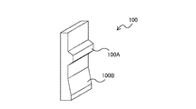
次に、このような壁杭用掘削孔102からケリーバー16およびバケット部20を取りだす。そして、壁杭用掘削孔102の壁面の安定化処理を行った後、壁杭用掘削孔102に鉄筋籠(図示略)を挿入し、コンクリートを打設する。これにより、図8に示すような、片面側のみに連続した拡幅部100Aが形成された壁杭100を形成することができる。なお、図8の壁杭100の底部には、断面三角形状の拡底部100Bが形成されているが、この拡底部100Bは、前記掘削装置1のバケット30の形状を台形状から三角形状に変え、この三角形状のバケットを壁杭100の底部に設置して、前記拡幅部100Aの場合と同様にして施工できる。
Next, the
本実施形態によれば、ケリーバー16を0°〜180°の範囲で正転および逆転することにより、バケット30が前記角度範囲で正転、逆転するため、掘削孔Aの壁面の一部側だけを確実に掘削できる。このため、掘削孔Aの厚み寸法が小さい場合であっても、片面側にのみ拡幅部100Aが形成された壁杭100を確実に施工できる。
According to the present embodiment, since the
また、掘削装置1によれば、バケット30を上げ下げして水平移動させたり、位置決めしたりすることなく、前記回転装置でケリーバー16を回転させつつ、前記移動装置でケリーバー16を水平移動させることにより、連続した拡幅部100Aが形成された壁杭100を簡単に施工できる。さらに、掘削孔A内に固定枠46を設けたので、掘削孔Aの壁面の硬さや状態の影響を受けることなく、スタビライザー移動部40を所定の高さ位置に確実に固定できる。
Further, according to the
なお、本発明は、前記実施形態には限定されない。例えば、ケリーバー16が0°〜180°の範囲で正転、逆転するように構成したが、これに限らず、構築される壁杭の片面側にのみ節部が形成されるような所定の角度範囲で正転、逆転できればよい。
また、前記実施形態では、片面側のみに連続した拡幅部100Aが形成された壁杭100を施工したが、例えば、ケリーバー16を水平移動させずに、拡幅部100Aが部分的に形成された壁杭や、外周の一部が拡径した拡径部が形成された丸杭を施工してもよい。この場合には、掘削装置1に油圧ジャッキ48等の移動装置を設けなくてもよい。
In addition, this invention is not limited to the said embodiment. For example, the
Moreover, in the said embodiment, although the
また、前記実施形態では、ケリーバー16を軸支する支持部材56をシリンダ52に取り付けたが、ロッド54に取り付けてもよい。また、掘削孔A内に固定枠46を設けていたが、特に設けなくてもよい。また、固定枠46を介して壁面を押圧するための押圧部材として油圧ジャッキ64を採用したが、これには限定されない。
In the above embodiment, the
また、前記実施形態では、壁杭の水平方向に連続した拡幅部を形成するようにしたが、例えば、バケット30を上方へと持ち上げるようなブーム14の操作等を行うことにより、鉛直方向に連続した拡幅部を形成してもよい。
Moreover, in the said embodiment, although the widened part continued in the horizontal direction of the wall pile was formed, for example, by operating the
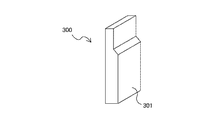
なお、施工する壁杭は、図8に示す形状のものに限定されない。例えば、図9は、本発明の第1変形例に係る、拡幅部301が形成された壁杭300を模式的に示す斜視図である。図9に示すように、壁杭300は、片側にのみ拡幅部301が形成されている。拡幅部301は、縦断面が縦方向に長い台形状であり、水平方向に沿って連続して形成されている。このような拡幅部301は、縦方向に長い台形状のバケット30が適用された前記掘削装置1を用いて、前記各実施形態と同様の手順で施工可能である。
The wall pile to be constructed is not limited to the shape shown in FIG. For example, FIG. 9 is a perspective view schematically showing a
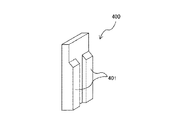
また、図10は、本発明の第2変形例に係る、拡幅部401が形成された壁杭400を模式的に示す斜視図である。図10に示すように、壁杭400は、片側にのみ拡幅部401が形成されている。拡幅部401は、縦断面が縦方向に長い台形状に形成され、水平方向に沿って間隔を置いて複数形成されている。このような拡幅部401は、縦方向に長い台形状のバケット30を適用した前記掘削装置1を用いて、まず、1つ目の各幅部401用の拡幅空間を形成した後、バケット30を閉じた状態でケリーバー16を水平移動させ、再度、バケット30を開いて2つ目の各幅部401用の拡幅空間を形成する。これにより、拡幅部401が間隔を置いて形成された壁杭400を施工できる。
FIG. 10 is a perspective view schematically showing a
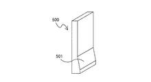
図11は、本発明の第3変形例に係る、拡幅部501が形成された壁杭500を模式的に示す斜視図である。図11に示すように、壁杭500は、片側にのみ拡幅部501が形成されている。このような拡幅部501は、縦断面三角形状に形成されている。このような拡幅部501は、前述したように、三角形状のバケット30が適用された前記掘削装置1を用いて、前記各実施形態と同様の手順で施工可能である。
FIG. 11 is a perspective view schematically showing a
図12は、本発明の第4変形例に係る、拡幅部601が形成された壁杭600を模式的に示す斜視図である。図12に示すように、壁杭600は、片側にのみ拡幅部601が形成されている。拡幅部601は、縦断面三角形状に形成され、水平方向に沿って間隔を置いて複数形成されている。このような拡幅部601は、三角形状のバケット30を適用した前記掘削装置1を用いて、まず、1つ目の各幅部601用の拡幅空間を形成した後、バケット30を閉じた状態でケリーバー16を水平移動させ、再度、バケット30を開いて2つ目の各幅部601用の拡幅空間を形成する。これにより、拡幅部601が間隔を置いて形成された壁杭600を施工できる。
以上のような形状の壁杭に限らず、任意の形状のものとすることができる。
FIG. 12 is a perspective view schematically showing a
Not only the wall pile of the above shape but an arbitrary shape can be used.
1 掘削装置
16 ケリーバー
30 バケット
50 スタビライザー
100 壁杭
100A 拡幅部(拡張部)
102A 拡張空間
A 掘削孔
G 地盤
DESCRIPTION OF
102A Expansion space A Drilling hole G Ground
Claims (3)
予め形成された掘削孔に、閉じた状態の前記バケットを挿入する工程と、
前記バケットを開きながら、前記ケリーバーを所定の角度範囲で正回転および逆回転を繰り返して、前記バケットで前記掘削孔の内壁面の一部を掘削することにより、前記節状の拡張部に対応する拡張空間を形成する工程と、
前記掘削孔の中にコンクリートを打設して、前記節状の拡張部が形成された杭を形成する工程とを備えることを特徴とする杭施工方法。 Using a drilling device comprising a kerry bar that rotates about the vertical direction and a bucket that is attached to the tip of the kelly bar and that can be opened and closed in the radial direction to rotate with the rotation of the kelly bar and excavate the ground. A pile construction method for constructing a pile in which an extended portion of
Inserting the closed bucket into a pre-formed excavation hole;
While the bucket is opened, the kelly bar is rotated forward and backward in a predetermined angle range, and a portion of the inner wall surface of the excavation hole is excavated with the bucket, thereby corresponding to the knot-like expansion portion. Forming an expansion space;
A pile construction method comprising: placing concrete in the excavation hole to form a pile in which the node-like expansion portion is formed.
前記掘削孔は長方形状の掘削孔であり、
片面側のみに節状の拡幅部が形成された壁杭を形成することを特徴とする杭施工方法。 In the pile construction method according to claim 1,
The excavation hole is a rectangular excavation hole,
The pile construction method characterized by forming the wall pile in which the nodal wide part was formed only in the single side | surface side.
Priority Applications (1)
| Application Number | Priority Date | Filing Date | Title |
|---|---|---|---|
| JP2004224142A JP4380452B2 (en) | 2004-07-30 | 2004-07-30 | Pile construction method and wall pile provided with a nodal extension constructed by the method |
Applications Claiming Priority (1)
| Application Number | Priority Date | Filing Date | Title |
|---|---|---|---|
| JP2004224142A JP4380452B2 (en) | 2004-07-30 | 2004-07-30 | Pile construction method and wall pile provided with a nodal extension constructed by the method |
Publications (2)
| Publication Number | Publication Date |
|---|---|
| JP2006045780A JP2006045780A (en) | 2006-02-16 |
| JP4380452B2 true JP4380452B2 (en) | 2009-12-09 |
Family
ID=36024679
Family Applications (1)
| Application Number | Title | Priority Date | Filing Date |
|---|---|---|---|
| JP2004224142A Expired - Fee Related JP4380452B2 (en) | 2004-07-30 | 2004-07-30 | Pile construction method and wall pile provided with a nodal extension constructed by the method |
Country Status (1)
| Country | Link |
|---|---|
| JP (1) | JP4380452B2 (en) |
Families Citing this family (1)
| Publication number | Priority date | Publication date | Assignee | Title |
|---|---|---|---|---|
| JP2009114696A (en) * | 2007-11-05 | 2009-05-28 | Ohbayashi Corp | Knotted pile |
-
2004
- 2004-07-30 JP JP2004224142A patent/JP4380452B2/en not_active Expired - Fee Related
Also Published As
| Publication number | Publication date |
|---|---|
| JP2006045780A (en) | 2006-02-16 |
Similar Documents
| Publication | Publication Date | Title |
|---|---|---|
| JP2009002156A (en) | Wall pile | |
| JP6638363B2 (en) | Drilling device and method of expanding pile hole | |
| JP4380452B2 (en) | Pile construction method and wall pile provided with a nodal extension constructed by the method | |
| JP2724548B2 (en) | 2-stage enlarged head | |
| JP4667309B2 (en) | Expanded excavation bucket | |
| JP7017962B2 (en) | Support pile construction method for existing structures | |
| JP2017128909A (en) | Drilling device | |
| JP4525228B2 (en) | Excavator, wall pile construction method, and wall pile | |
| KR102627320B1 (en) | Inclined grouting equipment for reinforcement of soft ground | |
| JP2019100124A (en) | Subsurface wall pile structure including expanded bottom | |
| JP2006219911A (en) | Pile mine widening device and method for cast-in-place concrete pile | |
| JP2003041614A (en) | Bucket excavator | |
| JP2594645Y2 (en) | Pile hole drilling head | |
| JP3129859B2 (en) | Expanded bucket | |
| JP4472373B2 (en) | Widening drilling rig | |
| JPS6358999B2 (en) | ||
| JPH06221077A (en) | Steering method and device for rotary excavator | |
| JP6845908B1 (en) | How to lay a wing excavator and a caisson skeleton | |
| JP4925948B2 (en) | Tunnel expansion excavator and tunnel construction method | |
| JP3612251B2 (en) | Slope anchoring machine | |
| JP4050267B2 (en) | Drilling machine | |
| JP2729940B2 (en) | Drilling rig | |
| JP2803526B2 (en) | Underground excavator | |
| JP2014034763A (en) | Widening excavation method | |
| JP4619886B2 (en) | Widening excavation method |
Legal Events
| Date | Code | Title | Description |
|---|---|---|---|
| A621 | Written request for application examination |
Free format text: JAPANESE INTERMEDIATE CODE: A621 Effective date: 20070620 |
|
| A977 | Report on retrieval |
Free format text: JAPANESE INTERMEDIATE CODE: A971007 Effective date: 20090601 |
|
| A131 | Notification of reasons for refusal |
Free format text: JAPANESE INTERMEDIATE CODE: A131 Effective date: 20090609 |
|
| A521 | Request for written amendment filed |
Free format text: JAPANESE INTERMEDIATE CODE: A523 Effective date: 20090803 |
|
| TRDD | Decision of grant or rejection written | ||
| A01 | Written decision to grant a patent or to grant a registration (utility model) |
Free format text: JAPANESE INTERMEDIATE CODE: A01 Effective date: 20090901 |
|
| A01 | Written decision to grant a patent or to grant a registration (utility model) |
Free format text: JAPANESE INTERMEDIATE CODE: A01 |
|
| A61 | First payment of annual fees (during grant procedure) |
Free format text: JAPANESE INTERMEDIATE CODE: A61 Effective date: 20090914 |
|
| FPAY | Renewal fee payment (event date is renewal date of database) |
Free format text: PAYMENT UNTIL: 20121002 Year of fee payment: 3 |
|
| R150 | Certificate of patent or registration of utility model |
Ref document number: 4380452 Country of ref document: JP Free format text: JAPANESE INTERMEDIATE CODE: R150 Free format text: JAPANESE INTERMEDIATE CODE: R150 |
|
| FPAY | Renewal fee payment (event date is renewal date of database) |
Free format text: PAYMENT UNTIL: 20121002 Year of fee payment: 3 |
|
| S531 | Written request for registration of change of domicile |
Free format text: JAPANESE INTERMEDIATE CODE: R313531 |
|
| FPAY | Renewal fee payment (event date is renewal date of database) |
Free format text: PAYMENT UNTIL: 20121002 Year of fee payment: 3 |
|
| R350 | Written notification of registration of transfer |
Free format text: JAPANESE INTERMEDIATE CODE: R350 |
|
| FPAY | Renewal fee payment (event date is renewal date of database) |
Free format text: PAYMENT UNTIL: 20121002 Year of fee payment: 3 |
|
| FPAY | Renewal fee payment (event date is renewal date of database) |
Free format text: PAYMENT UNTIL: 20131002 Year of fee payment: 4 |
|
| FPAY | Renewal fee payment (event date is renewal date of database) |
Free format text: PAYMENT UNTIL: 20131002 Year of fee payment: 4 |
|
| FPAY | Renewal fee payment (event date is renewal date of database) |
Free format text: PAYMENT UNTIL: 20141002 Year of fee payment: 5 |
|
| LAPS | Cancellation because of no payment of annual fees |