JP4386830B2 - Honeycomb filter for exhaust gas purification - Google Patents
Honeycomb filter for exhaust gas purification Download PDFInfo
- Publication number
- JP4386830B2 JP4386830B2 JP2004501785A JP2004501785A JP4386830B2 JP 4386830 B2 JP4386830 B2 JP 4386830B2 JP 2004501785 A JP2004501785 A JP 2004501785A JP 2004501785 A JP2004501785 A JP 2004501785A JP 4386830 B2 JP4386830 B2 JP 4386830B2
- Authority
- JP
- Japan
- Prior art keywords
- filler
- porosity
- honeycomb filter
- columnar body
- weight
- Prior art date
- Legal status (The legal status is an assumption and is not a legal conclusion. Google has not performed a legal analysis and makes no representation as to the accuracy of the status listed.)
- Expired - Lifetime
Links
Images

Classifications
-
- B—PERFORMING OPERATIONS; TRANSPORTING
- B01—PHYSICAL OR CHEMICAL PROCESSES OR APPARATUS IN GENERAL
- B01D—SEPARATION
- B01D53/00—Separation of gases or vapours; Recovering vapours of volatile solvents from gases; Chemical or biological purification of waste gases, e.g. engine exhaust gases, smoke, fumes, flue gases, aerosols
- B01D53/34—Chemical or biological purification of waste gases
- B01D53/92—Chemical or biological purification of waste gases of engine exhaust gases
- B01D53/94—Chemical or biological purification of waste gases of engine exhaust gases by catalytic processes
- B01D53/9445—Simultaneously removing carbon monoxide, hydrocarbons or nitrogen oxides making use of three-way catalysts [TWC] or four-way-catalysts [FWC]
- B01D53/9454—Simultaneously removing carbon monoxide, hydrocarbons or nitrogen oxides making use of three-way catalysts [TWC] or four-way-catalysts [FWC] characterised by a specific device
-
- F—MECHANICAL ENGINEERING; LIGHTING; HEATING; WEAPONS; BLASTING
- F01—MACHINES OR ENGINES IN GENERAL; ENGINE PLANTS IN GENERAL; STEAM ENGINES
- F01N—GAS-FLOW SILENCERS OR EXHAUST APPARATUS FOR MACHINES OR ENGINES IN GENERAL; GAS-FLOW SILENCERS OR EXHAUST APPARATUS FOR INTERNAL-COMBUSTION ENGINES
- F01N13/00—Exhaust or silencing apparatus characterised by constructional features
- F01N13/011—Exhaust or silencing apparatus characterised by constructional features having two or more purifying devices arranged in parallel
- F01N13/017—Exhaust or silencing apparatus characterised by constructional features having two or more purifying devices arranged in parallel the purifying devices are arranged in a single housing
-
- F—MECHANICAL ENGINEERING; LIGHTING; HEATING; WEAPONS; BLASTING
- F01—MACHINES OR ENGINES IN GENERAL; ENGINE PLANTS IN GENERAL; STEAM ENGINES
- F01N—GAS-FLOW SILENCERS OR EXHAUST APPARATUS FOR MACHINES OR ENGINES IN GENERAL; GAS-FLOW SILENCERS OR EXHAUST APPARATUS FOR INTERNAL-COMBUSTION ENGINES
- F01N13/00—Exhaust or silencing apparatus characterised by constructional features
- F01N13/18—Construction facilitating manufacture, assembly, or disassembly
- F01N13/1888—Construction facilitating manufacture, assembly, or disassembly the housing of the assembly consisting of two or more parts, e.g. two half-shells
-
- F—MECHANICAL ENGINEERING; LIGHTING; HEATING; WEAPONS; BLASTING
- F01—MACHINES OR ENGINES IN GENERAL; ENGINE PLANTS IN GENERAL; STEAM ENGINES
- F01N—GAS-FLOW SILENCERS OR EXHAUST APPARATUS FOR MACHINES OR ENGINES IN GENERAL; GAS-FLOW SILENCERS OR EXHAUST APPARATUS FOR INTERNAL-COMBUSTION ENGINES
- F01N3/00—Exhaust or silencing apparatus having means for purifying, rendering innocuous, or otherwise treating exhaust
- F01N3/02—Exhaust or silencing apparatus having means for purifying, rendering innocuous, or otherwise treating exhaust for cooling, or for removing solid constituents of, exhaust
- F01N3/021—Exhaust or silencing apparatus having means for purifying, rendering innocuous, or otherwise treating exhaust for cooling, or for removing solid constituents of, exhaust by means of filters
- F01N3/022—Exhaust or silencing apparatus having means for purifying, rendering innocuous, or otherwise treating exhaust for cooling, or for removing solid constituents of, exhaust by means of filters characterised by specially adapted filtering structure, e.g. honeycomb, mesh or fibrous
- F01N3/0222—Exhaust or silencing apparatus having means for purifying, rendering innocuous, or otherwise treating exhaust for cooling, or for removing solid constituents of, exhaust by means of filters characterised by specially adapted filtering structure, e.g. honeycomb, mesh or fibrous the structure being monolithic, e.g. honeycombs
-
- F—MECHANICAL ENGINEERING; LIGHTING; HEATING; WEAPONS; BLASTING
- F01—MACHINES OR ENGINES IN GENERAL; ENGINE PLANTS IN GENERAL; STEAM ENGINES
- F01N—GAS-FLOW SILENCERS OR EXHAUST APPARATUS FOR MACHINES OR ENGINES IN GENERAL; GAS-FLOW SILENCERS OR EXHAUST APPARATUS FOR INTERNAL-COMBUSTION ENGINES
- F01N2330/00—Structure of catalyst support or particle filter
- F01N2330/06—Ceramic, e.g. monoliths
-
- F—MECHANICAL ENGINEERING; LIGHTING; HEATING; WEAPONS; BLASTING
- F01—MACHINES OR ENGINES IN GENERAL; ENGINE PLANTS IN GENERAL; STEAM ENGINES
- F01N—GAS-FLOW SILENCERS OR EXHAUST APPARATUS FOR MACHINES OR ENGINES IN GENERAL; GAS-FLOW SILENCERS OR EXHAUST APPARATUS FOR INTERNAL-COMBUSTION ENGINES
- F01N2330/00—Structure of catalyst support or particle filter
- F01N2330/14—Sintered material
-
- F—MECHANICAL ENGINEERING; LIGHTING; HEATING; WEAPONS; BLASTING
- F01—MACHINES OR ENGINES IN GENERAL; ENGINE PLANTS IN GENERAL; STEAM ENGINES
- F01N—GAS-FLOW SILENCERS OR EXHAUST APPARATUS FOR MACHINES OR ENGINES IN GENERAL; GAS-FLOW SILENCERS OR EXHAUST APPARATUS FOR INTERNAL-COMBUSTION ENGINES
- F01N2330/00—Structure of catalyst support or particle filter
- F01N2330/30—Honeycomb supports characterised by their structural details
- F01N2330/48—Honeycomb supports characterised by their structural details characterised by the number of flow passages, e.g. cell density
-
- F—MECHANICAL ENGINEERING; LIGHTING; HEATING; WEAPONS; BLASTING
- F01—MACHINES OR ENGINES IN GENERAL; ENGINE PLANTS IN GENERAL; STEAM ENGINES
- F01N—GAS-FLOW SILENCERS OR EXHAUST APPARATUS FOR MACHINES OR ENGINES IN GENERAL; GAS-FLOW SILENCERS OR EXHAUST APPARATUS FOR INTERNAL-COMBUSTION ENGINES
- F01N2450/00—Methods or apparatus for fitting, inserting or repairing different elements
- F01N2450/28—Methods or apparatus for fitting, inserting or repairing different elements by using adhesive material, e.g. cement
-
- F—MECHANICAL ENGINEERING; LIGHTING; HEATING; WEAPONS; BLASTING
- F01—MACHINES OR ENGINES IN GENERAL; ENGINE PLANTS IN GENERAL; STEAM ENGINES
- F01N—GAS-FLOW SILENCERS OR EXHAUST APPARATUS FOR MACHINES OR ENGINES IN GENERAL; GAS-FLOW SILENCERS OR EXHAUST APPARATUS FOR INTERNAL-COMBUSTION ENGINES
- F01N2510/00—Surface coverings
- F01N2510/06—Surface coverings for exhaust purification, e.g. catalytic reaction
- F01N2510/065—Surface coverings for exhaust purification, e.g. catalytic reaction for reducing soot ignition temperature
-
- F—MECHANICAL ENGINEERING; LIGHTING; HEATING; WEAPONS; BLASTING
- F01—MACHINES OR ENGINES IN GENERAL; ENGINE PLANTS IN GENERAL; STEAM ENGINES
- F01N—GAS-FLOW SILENCERS OR EXHAUST APPARATUS FOR MACHINES OR ENGINES IN GENERAL; GAS-FLOW SILENCERS OR EXHAUST APPARATUS FOR INTERNAL-COMBUSTION ENGINES
- F01N3/00—Exhaust or silencing apparatus having means for purifying, rendering innocuous, or otherwise treating exhaust
- F01N3/02—Exhaust or silencing apparatus having means for purifying, rendering innocuous, or otherwise treating exhaust for cooling, or for removing solid constituents of, exhaust
- F01N3/021—Exhaust or silencing apparatus having means for purifying, rendering innocuous, or otherwise treating exhaust for cooling, or for removing solid constituents of, exhaust by means of filters
- F01N3/023—Exhaust or silencing apparatus having means for purifying, rendering innocuous, or otherwise treating exhaust for cooling, or for removing solid constituents of, exhaust by means of filters using means for regenerating the filters, e.g. by burning trapped particles
-
- F—MECHANICAL ENGINEERING; LIGHTING; HEATING; WEAPONS; BLASTING
- F01—MACHINES OR ENGINES IN GENERAL; ENGINE PLANTS IN GENERAL; STEAM ENGINES
- F01N—GAS-FLOW SILENCERS OR EXHAUST APPARATUS FOR MACHINES OR ENGINES IN GENERAL; GAS-FLOW SILENCERS OR EXHAUST APPARATUS FOR INTERNAL-COMBUSTION ENGINES
- F01N3/00—Exhaust or silencing apparatus having means for purifying, rendering innocuous, or otherwise treating exhaust
- F01N3/02—Exhaust or silencing apparatus having means for purifying, rendering innocuous, or otherwise treating exhaust for cooling, or for removing solid constituents of, exhaust
- F01N3/021—Exhaust or silencing apparatus having means for purifying, rendering innocuous, or otherwise treating exhaust for cooling, or for removing solid constituents of, exhaust by means of filters
- F01N3/033—Exhaust or silencing apparatus having means for purifying, rendering innocuous, or otherwise treating exhaust for cooling, or for removing solid constituents of, exhaust by means of filters in combination with other devices
- F01N3/035—Exhaust or silencing apparatus having means for purifying, rendering innocuous, or otherwise treating exhaust for cooling, or for removing solid constituents of, exhaust by means of filters in combination with other devices with catalytic reactors
-
- Y—GENERAL TAGGING OF NEW TECHNOLOGICAL DEVELOPMENTS; GENERAL TAGGING OF CROSS-SECTIONAL TECHNOLOGIES SPANNING OVER SEVERAL SECTIONS OF THE IPC; TECHNICAL SUBJECTS COVERED BY FORMER USPC CROSS-REFERENCE ART COLLECTIONS [XRACs] AND DIGESTS
- Y02—TECHNOLOGIES OR APPLICATIONS FOR MITIGATION OR ADAPTATION AGAINST CLIMATE CHANGE
- Y02T—CLIMATE CHANGE MITIGATION TECHNOLOGIES RELATED TO TRANSPORTATION
- Y02T10/00—Road transport of goods or passengers
- Y02T10/10—Internal combustion engine [ICE] based vehicles
- Y02T10/12—Improving ICE efficiencies
-
- Y—GENERAL TAGGING OF NEW TECHNOLOGICAL DEVELOPMENTS; GENERAL TAGGING OF CROSS-SECTIONAL TECHNOLOGIES SPANNING OVER SEVERAL SECTIONS OF THE IPC; TECHNICAL SUBJECTS COVERED BY FORMER USPC CROSS-REFERENCE ART COLLECTIONS [XRACs] AND DIGESTS
- Y10—TECHNICAL SUBJECTS COVERED BY FORMER USPC
- Y10T—TECHNICAL SUBJECTS COVERED BY FORMER US CLASSIFICATION
- Y10T428/00—Stock material or miscellaneous articles
- Y10T428/24—Structurally defined web or sheet [e.g., overall dimension, etc.]
- Y10T428/24149—Honeycomb-like
-
- Y—GENERAL TAGGING OF NEW TECHNOLOGICAL DEVELOPMENTS; GENERAL TAGGING OF CROSS-SECTIONAL TECHNOLOGIES SPANNING OVER SEVERAL SECTIONS OF THE IPC; TECHNICAL SUBJECTS COVERED BY FORMER USPC CROSS-REFERENCE ART COLLECTIONS [XRACs] AND DIGESTS
- Y10—TECHNICAL SUBJECTS COVERED BY FORMER USPC
- Y10T—TECHNICAL SUBJECTS COVERED BY FORMER US CLASSIFICATION
- Y10T428/00—Stock material or miscellaneous articles
- Y10T428/24—Structurally defined web or sheet [e.g., overall dimension, etc.]
- Y10T428/24149—Honeycomb-like
- Y10T428/24157—Filled honeycomb cells [e.g., solid substance in cavities, etc.]
Landscapes
- Engineering & Computer Science (AREA)
- Chemical & Material Sciences (AREA)
- Combustion & Propulsion (AREA)
- General Engineering & Computer Science (AREA)
- Mechanical Engineering (AREA)
- Oil, Petroleum & Natural Gas (AREA)
- Analytical Chemistry (AREA)
- General Chemical & Material Sciences (AREA)
- Environmental & Geological Engineering (AREA)
- Chemical Kinetics & Catalysis (AREA)
- Biomedical Technology (AREA)
- Health & Medical Sciences (AREA)
- Filtering Materials (AREA)
- Processes For Solid Components From Exhaust (AREA)
- Filtering Of Dispersed Particles In Gases (AREA)
- Cylinder Crankcases Of Internal Combustion Engines (AREA)
- Filters For Electric Vacuum Cleaners (AREA)
Abstract
Description
関連出願の記載
本出願は、2002年4月11日に出願された日本国特許出願2002−109717号を基礎出願として優先権主張する出願である。
技術分野
本発明は、ディーゼルエンジン等の内燃機関から排出される排気ガス中のパティキュレート等を除去するフィルタとして用いられる排気ガス浄化用ハニカムフィルタに関する。
背景技術
バス、トラック等の車両や建設機械等の内燃機関から排出される排気ガス中に含有されるパティキュレート(微粒子)が環境や人体に害を及ぼすことが最近問題となっている。
この排気ガスを多孔質セラミックに通過させ、排気ガス中のパティキュレートを捕集して、排気ガスを浄化することができるセラミックフィルタが種々提案されている。
このようなセラミックフィルタは、通常、一方向に多数の貫通孔が並設された柱状体の貫通孔同士を隔てる隔壁がフィルタとして機能するようになっている。
即ち、上記ハニカムフィルタにおいて、上記柱状体に形成された貫通孔は、排気ガスの入り口側又は出口側の端部のいずれかが充填材により、所謂、市松模様となるように目封じされ、一の貫通孔に流入した排気ガスは、必ず貫通孔を隔てる隔壁を通過した後、他の貫通孔から流出するようになっており、排気ガスがこの隔壁を通過する際、パティキュレートが隔壁部分で捕捉され、排気ガスが浄化される。
このような排気ガスの浄化作用に伴い、ハニカムフィルタの貫通孔を隔てる隔壁部分には、次第にパティキュレートが堆積し、目詰まりを起こして通気を妨げるようになる。このため、上記ハニカムフィルタでは、定期的にヒータ等の加熱手段を用いて目詰まりの原因となっているパティキュレートを燃焼除去して再生する再生処理を行う必要がある。
従来、このようなハニカムフィルタにおいて、貫通孔の端部に充填された充填材は、貫通孔に流入した排気ガスがハニカムフィルタを素通りしてしまうことを防止し、確実に上記排気ガスが隔壁を通過するようにするために、緻密化されていることが望ましいと考えられていた(例えば、特開昭59−225718号公報参照)。
しかしながら、このような従来のハニカムフィルタにおいて、上記柱状体は多孔質セラミックからなるものであり、この柱状体の熱膨張率と、緻密化された充填材の熱膨張率とが異なるものであった。
そのため、このようなハニカムフィルタは、例えば、製造時の焼成工程で、上記柱状体の熱膨張率と充填材の熱膨張率との相違に起因して、充填材と該充填材に接触する部分の隔壁との間に大きな熱応力が作用し、上記充填材と隔壁との間に隙間が形成されたり、上記充填材や該充填材に接触する部分の隔壁にクラックが発生したりすることがあった。
このような問題を解決するために、ハニカムフィルタと充填材との間の熱膨張係数を調整することによって、製造過程で、クラックが起こらないようにしたフィルタが開示されている(特開昭57−42316号公報参照)。
しかしながら、ハニカムフィルタの製造時に、充填材と隔壁との間に隙間が形成されておらず、充填材や該充填材に接触する部分の隔壁にクラックが発生していない場合であっても、このようなハニカムフィルタを用いて実際に排気ガスの浄化を行うと、高温の排気ガスや、ハニカムフィルタの再生処理時等の加熱によって繰り返し印加される冷熱サイクルによって、ハニカムフィルタの充填材と、該充填材に接触する部分の隔壁との間に、柱状体の熱膨張率と隔壁の熱膨張率との相違に起因した熱応力が蓄積され、上記充填材と隔壁との間に隙間が形成されたり、上記充填材や該充填材に接触する部分の隔壁にクラックが発生したりすることがあった。
さらに、昨今、上記ハニカムフィルタの再生処理を、上述したようなヒータ等の加熱手段を用いる方法に代えて、ハニカムフィルタの気孔中に酸化触媒を担持させることで、上記ハニカムフィルタに流入した排気ガスに含まれる炭化水素と、上記酸化触媒とを反応させ、その際に発生する熱を利用したハニカムフィルタの再生処理を行う考え方がある。このようにして再生処理を行うハニカムフィルタでは、ハニカムフィルタの気孔中に酸化触媒を担持させるため、パティキュレートによる気孔の目詰まりが発生しやすいこと、及び、大量の熱を発生させるためには、できるだけ多くの酸化触媒を担持させる必要があること等の理由から、その気孔率を高くする必要があった。
ところが、このような高気孔率のハニカムフィルタは、柱状体の熱膨張率と、緻密化された充填材の熱膨張率との差はより大きくなるため、上述したような、製造時の焼成工程や、使用時の高温の排気ガス等に起因して充填材と隔壁との間に生じる熱応力により、充填材と隔壁との間に隙間が形成されたり、充填材や該充填材に接触する部分の隔壁にクラックが発生したりする問題が生じやすいものであった。
加えて、このような高い気孔率のハニカムフィルタに、触媒を担持させるためには、通常、高比表面積を有するγ−アルミナ等をハニカムフィルタにコーティングして、触媒担持膜を形成し、その触媒担持膜上に触媒となる貴金属を分散担持させる方法が用いられるが、充填材と該充填材に接触する部分の隔壁との間に侵入して触媒担持膜が形成されてしまうことがあり、これらの材料の熱膨張率の差に起因した熱応力により、クラック等が発生する問題が生じることもあった。
なお、従来、排気ガス中から捕集したパティキュレートを逆洗浄の際に剥離させ易くするために充填材を通気性にしたハニカムフィルタ(特開平7−332064号公報参照)、浄化性能を向上させるために充填材の気孔率を限定したハニカムフィルタ(特開2003−3823号公報参照)が開示されている。しかしながら、これらのハニカムフィルタは、上述の問題を認識したものではなく、その目的が全く異なっているため、技術的な前提が全く異なるものである。
発明の要約
本発明は、これらの問題を解決するためになされたもので、充填材と隔壁との間に隙間が形成されたり、上記充填材や該充填材に接触する部分の壁部にクラックが発生したりすることがなく、耐久性に優れる排気ガス浄化用ハニカムフィルタを提供することを目的とするものである。
本発明の排気ガス浄化用ハニカムフィルタは、多数の貫通孔が壁部を隔てて長手方向に並設された、多孔質セラミックからなる柱状体の一方の端部では、上記貫通孔のうち、所定の貫通孔が充填材により充填され、一方、上記柱状体の他方の端部で、上記一方の端部で前記充填材により充填されていない貫通孔が充填材により充填され、上記壁部の一部又は全部が粒子捕集用フィルタとして機能するように構成された排気ガス浄化用ハニカムフィルタであって、
上記柱状体の気孔率は、20〜80%であり、上記充填材の気孔率は、90%以下であり、かつ、上記柱状体の気孔率の0.15〜4.0倍であることを特徴とするものである。
また、本発明の排気ガス浄化用ハニカムフィルタに触媒が担持される場合には、上記柱状体及び充填材の気孔率は、本発明の排気ガス浄化用ハニカムフィルタに触媒担持膜が付与された後に測定されることが望ましい。
発明の詳細な開示
本発明は、多数の貫通孔が壁部を隔てて長手方向に並設された、多孔質セラミックからなる柱状体の一方の端部では、上記貫通孔のうち、所定の貫通孔が充填材により充填され、一方、上記柱状体の他方の端部で、上記一方の端部で前記充填材により充填されていない貫通孔が充填材により充填され、上記壁部の一部又は全部が粒子捕集用フィルタとして機能するように構成された排気ガス浄化用ハニカムフィルタであって、
上記柱状体の気孔率は、20〜80%であり、上記充填材の気孔率は、90%以下であり、かつ、上記柱状体の気孔率の0.15〜4.0倍であることを特徴とする排気ガス浄化用ハニカムフィルタである。
また、本発明の排気ガス浄化用ハニカムフィルタに触媒が担持される場合には、上記柱状体及び充填材の気孔率は、本発明の排気ガス浄化用ハニカムフィルタに触媒担持膜が付与された後に測定されることが望ましい。
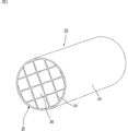
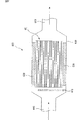
図1(a)は、本発明の排気ガス浄化用ハニカムフィルタ(以下、単に本発明のハニカムフィルタともいう)の一例を模式的に示した斜視図であり、(b)は、そのA−A線断面図である。
図1(a)に示したように、本発明のハニカムフィルタ10は、多数の貫通孔11が壁部13を隔てて長手方向に並設された一の多孔質セラミック焼結体からなる柱状体の一方の端部、又は、他方の端部における貫通孔11に充填材12が充填されており、壁部13の全部が粒子捕集用フィルタとして機能するように構成されている。
即ち、ハニカムフィルタ10に形成された貫通孔11は、図1(b)に示したように、排気ガスの入り口側又は出口側のいずれかが充填材12により目封じされ、一の貫通孔11に流入した排気ガスは、必ず貫通孔11を隔てる壁部13を通過した後、他の貫通孔11から流出されるようになっている。
そして、本発明のハニカムフィルタ10に流入した排気ガス中に含まれるパティキュレートは、壁部13を通過する際、壁部13で捕捉され、排気ガスが浄化されるようになっている。
このような構成のハニカムフィルタ10が内燃機関の排気通路に配設される排気ガス浄化装置に設置されて使用される。
なお、上記排気ガス浄化装置については後述する。
本発明のハニカムフィルタ10において、上記柱状体は、多数の貫通孔11が壁部13を隔てて長手方向に並設された多孔質セラミックからなる柱状の部材であり、上記柱状体の気孔率は20〜80%である。上記柱状体の気孔率が20%未満であると、ハニカムフィルタ10がすぐに目詰まりを起こすことがあり、一方、上記柱状体の気孔率が80%を超えると、ハニカムフィルタ10の強度が低下して容易に破壊されることがある。
なお、上記気孔率は、例えば、水銀圧入法、アルキメデス法及び走査型電子顕微鏡(SEM)による観測等、従来公知の方法により測定することができる。
上記柱状体の大きさとしては特に限定されず、使用する内燃機関の排気通路の大きさ等を考慮して適宜決定される。また、その形状としては、柱状であれば特に限定されず、例えば、円柱状、楕円柱状、角柱状等任意の形状を挙げることができるが、通常、図1に示したように、円柱状のものがよく用いられる。
上記柱状体を構成する多孔質セラミックとしては特に限定されず、例えば、コージェライト、アルミナ、シリカ、ムライト等の酸化物セラミック、炭化ケイ素、炭化ジルコニウム、炭化チタン、炭化タンタル、炭化タングステン等の炭化物セラミック、及び、窒化アルミニウム、窒化ケイ素、窒化ホウ素、窒化チタン等の窒化物セラミックを挙げることができるが、通常、コージェライト等の酸化物セラミックが使用される。安価に製造することができるとともに、比較的熱膨張係数が小さく、使用中に酸化されることがないからである。なお、上述したセラミックに金属珪素を配合した珪素含有セラミック、珪素や珪酸塩化合物で結合されたセラミックも用いることができる。
上記柱状体の平均気孔径は5〜100μm程度であることが望ましい。平均気孔径が5μm未満であると、パティキュレートが容易に目詰まりを起こすことがある。一方、平均気孔径が100μmを超えると、パティキュレートが気孔を通り抜けてしまい、該パティキュレートを捕集することができず、フィルタとして機能することができないことがある。
また、本発明のハニカムフィルタ10は、上記柱状体の一方の端部、又は、他方の端部における貫通孔11に充填材12が充填されたものであり、この充填材12の気孔率は90%以下である。充填材12の気孔率が90%を超えると、充填材12の強度が低下してしまい、ハニカムフィルタ10に流入される高温の排気ガスや、再生時の冷熱サイクル等に起因する熱衝撃等により充填材12が容易に破壊されてしまう。また、充填材12が破壊されない場合であっても、パティキュレートが充填材12の内部を通過してしまい、排気ガス浄化用のフィルタとして充分に機能することができなくなる。
また、上記柱状体の気孔率に対する充填材12の気孔率の倍率は、その下限が0.15倍であり、その上限が4.0倍である。
上記柱状体の気孔率に対する充填材12の気孔率の倍率の下限が0.15倍未満であると、柱状体の熱膨張率と、充填材12の熱膨張率との差が大きくなりすぎ、製造時の焼成工程において、上記熱膨張率の相違に起因して充填材12と壁部13との間に隙間や、充填材12や充填材12に接触する部分の壁部13にクラックが発生する。一方、上記柱状体の気孔率に対する充填材12の気孔率の倍率の上限が4.0倍を超えると、やはり上記柱状体の熱膨張率と、充填材12の熱膨張率との差が大きくなりすぎ、製造時の焼成工程において、熱膨張率の相違に起因して充填材12と壁部13との間に隙間や、充填材12や充填材12に接触する部分の壁部13にクラックが発生し、強度が低下すると推定される。
また、上記柱状体の気孔率に対する充填材12の気孔率の倍率の下限は、0.25倍であることが望ましく、その上限は1.5倍であることが望ましい。
上記柱状体の気孔率に対する充填材12の気孔率の倍率の下限が0.25倍未満であると、柱状体の熱膨張率と、充填材12の熱膨張率との差が比較的大きく、製造時の焼成工程において、上述した隙間やクラックが発生していない場合であっても、使用時の高温の排気ガスや再生処理時の加熱等により繰り返し印加される冷熱サイクルにより、充填材12と壁部13との間に隙間が生じたり、充填材12や充填材12に接触する部分の壁部13にクラックが発生し、強度が低下することがある。また、本発明のハニカムフィルタに触媒担持膜が形成されている場合には、触媒担持膜が充填材12と充填材12に接触する部分の壁部13との間に侵入して形成されていることがあり、この場合には、触媒担持膜と充填材12、充填材12に接触する部分の壁部13との熱膨張率の差に起因した熱応力によっても、同様にクラックが発生し、強度が低下することがある。
一方、上記柱状体の気孔率に対する充填材12の気孔率の倍率の上限が1.5倍を超えると、やはり柱状体の熱膨張率と、充填材12の熱膨張率との差が比較的大きく、製造時の焼成工程において、上述したような隙間やクラックが発生していない場合であっても、高温の排気ガスや再生処理時の加熱等により繰り返し印加される冷熱サイクルに起因した熱応力が充填材12や充填材12に接触する部分の壁部13に蓄積され、充填材12と壁部13との間に隙間が生じたり、充填材12や充填材12に接触する部分の壁部13にクラックが発生し、強度が低下すると推定される。さらに、繰り返し長期間使用すると、高温の排気ガスが気孔率の高い充填材12部分に集中するため熱衝撃を受けやすく、充填材12が破壊されてしまうことがある。また、本発明のハニカムフィルタに触媒担持膜が形成されている場合には、触媒担持膜が充填材12と充填材12に接触する部分の壁部13との間に侵入して形成されていることがあり、この場合には、触媒担持膜と充填材12、充填材12に接触する部分の壁部13との熱膨張率の差に起因した熱応力によっても、同様にクラックが発生することがある。
本発明のハニカムフィルタに触媒担持膜が1g/L以上形成されている場合には、上記柱状体の気孔率に対する充填材12の気孔率の倍率は、0.3〜1.2倍であることがより好ましい。
また、上述したように、充填材12の気孔率の上限は90%であるが、本発明のハニカムフィルタ10において、柱状体の気孔率の下限が20%であり、上記柱状体の気孔率に対する充填材12の気孔率の倍率の下限が0.15倍であることから、充填材12の気孔率の下限は3%となる。
充填材12の気孔率が3%未満であると、充填材12と壁部13との接着強度が低くなるため、このようなハニカムフィルタを用いて排気ガスの浄化を行うと、高温の排気ガスや、再生処理時の加熱等に起因する熱衝撃によって、充填材と壁部との間に隙間やクラックが形成され、また、充填材12が抜け落ちてしまうことがある。これは、ハニカムフィルタの充填材の気孔率を3%未満と低くしようとすると、充填材の層を形成する際に使用する充填材ペーストの粘度が高くなり非常に流動しにくくなる。このような高粘度の充填材ペーストは、柱状体となるセラミック成形体の所定の貫通孔の端部に隙間なく、かつ、セラミック成形体の端面から充分な幅で充填させることが非常に困難となる。従って、製造するハニカムフィルタの充填材と、壁部との接触面積が小さくなり、充填材と壁部との接着強度が低くなるものと考えられる。
なお、上記ハニカムフィルタの製造方法については、後で詳述する。
このような充填材12は多孔質セラミックからなるものであることが望ましい。
本発明のハニカムフィルタ10において、充填材12が充填された柱状体は多孔質セラミックからなるものであるため、充填材12を上記柱状体と同じ多孔質セラミックとすることで、両者の接着強度を高くすることができるとともに、充填材12の気孔率が上述した条件を満たすように調整することで、上記柱状体の熱膨張率と充填材12の熱膨張率との整合を図ることができ、製造時や使用時の熱応力によって充填材12と壁部13との間に隙間が生じたり、充填材12や充填材12に接触する部分の壁部13にクラックが発生したりすることを防止することができる。
充填材12が多孔質セラミックからなる場合、その材料としては特に限定されず、例えば、上述した柱状体を構成するセラミック材料と同様の材料を挙げることができる。
また、本発明のハニカムフィルタにおいて、柱状体は、複数の貫通孔が隔壁を隔てて長手方向に並設された角柱形状の多孔質セラミック部材がシール材層を介して複数個結束されて構成されていることが望ましい。上記柱状体が複数の多孔質セラミック部材に分割されているため、使用中に多孔質セラミック部材に作用する熱応力を低減させることができ、本発明のハニカムフィルタを非常に耐熱性に優れたものとすることができる。また、多孔質セラミック部材の個数を増減させることで自由にその大きさを調整することができる。
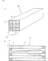
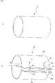
図2は、本発明のハニカムフィルタの別の一例を模式的に示した斜視図であり、図3(a)は、図2に示したハニカムフィルタを構成する多孔質セラミック部材の一例を模式的に示した斜視図であり、(b)は、そのB−B線断面図である。
図2に示したように、本発明のハニカムフィルタ20は、多孔質セラミック部材30がシール材層24を介して複数個結束されてセラミックブロック25を構成し、このセラミックブロック25の周囲にもシール材層26が形成されている。また、この多孔質セラミック部材30は、図3に示したように、長手方向に多数の貫通孔31が並設され、貫通孔31同士を隔てる隔壁33がフィルタとして機能するようになっている。
即ち、多孔質セラミック部材30に形成された貫通孔31は、図3(b)に示したように、排気ガスの入り口側又は出口側の端部のいずれかが充填材32により目封じされ、一の貫通孔31に流入した排気ガスは、必ず貫通孔31を隔てる隔壁33を通過した後、他の貫通孔31から流出されるようになっている。
また、セラミックブロック25の周囲に形成されたシール材層26は、ハニカムフィルタ20を内燃機関の排気通路に設置した際、セラミックブロック25の外周部から排気ガスが漏れ出すことを防止する目的で設けられているものである。
なお、図3(b)中、矢印は排気ガスの流れを示している。
このような構成のハニカムフィルタ20が内燃機関の排気通路に配設された排気ガス浄化装置に設置され、内燃機関より排出された排気ガス中のパティキュレートは、このハニカムフィルタ20を通過する際に隔壁33により捕捉され、排気ガスが浄化される。
このようなハニカムフィルタ20は、極めて耐熱性に優れ、再生処理等も容易であるため、種々の大型車両やディーゼルエンジン搭載車両等に使用されている。
このような構造の本発明のハニカムフィルタ20において、柱状体(セラミックブロック25から充填材32を除いた部材)の気孔率は、20〜80%であり、充填材32の気孔率は、90%以下であり、かつ、上記柱状体の気孔率に対する充填材32の気孔率の倍率は、その下限が0.15倍であり、上限は4.0倍である。上記図1を用いたハニカムフィルタ10で説明した通りである。
また、本発明のハニカムフィルタ10において説明した充填材12と同様に、上記柱状体の気孔率に対する充填材32の気孔率の倍率は、その下限は0.25倍であり、上限は1.5倍であることが望ましく、充填材32の気孔率の下限は3%となり、さらに、充填材32は多孔質セラミックからなるものであることが望ましい。
多孔質セラミック部材30の材料としては特に限定されず、上述した本発明のハニカムフィルタ10の柱状体を構成するセラミック材料と同様の材料を挙げることができるが、これらのなかでは、耐熱性が大きく、機械的特性に優れ、かつ、熱伝導率も大きい炭化ケイ素が望ましい。
このような多孔質セラミック部材30を製造する際に使用するセラミックの粒径としては特に限定されないが、後の焼成工程で収縮が少ないものが望ましく、例えば、0.3〜50μm程度の平均粒径を有する粉末100重量部と、0.1〜1.0μm程度の平均粒径を有する粉末5〜65重量部とを組み合わせたものが望ましい。上記粒径のセラミック粉末を上記配合で混合することで、多孔質セラミック部材30を製造することができるからである。
本発明のハニカムフィルタ20では、このような多孔質セラミック部材30がシール材層24を介して複数個結束されてセラミックブロック25が構成されており、このセラミックブロック25の外周にもシール材層26が形成されている。
即ち、本発明のハニカムフィルタ20において、シール材層は、多孔質セラミック部材30間、及び、セラミックブロック25の外周に形成されており、多孔質セラミック部材30間に形成されたシール材層(シール材層24)は、複数の多孔質セラミック部材30同士を結束する接着剤層として機能し、一方、セラミックブロック25の外周に形成されたシール材層(シール材層26)は、本発明のハニカムフィルタ20を内燃機関の排気通路に設置した際、セラミックブロック25の外周から排気ガスが漏れ出すことを防止するための封止材として機能する。
上記シール材層(シール材層24及びシール材層26)を構成する材料としては特に限定されず、例えば、無機バインダー、有機バインダー、無機繊維及び無機粒子からなるもの等を挙げることができる。
なお、上述した通り、本発明のハニカムフィルタ20において、シール材層は、多孔質セラミック部材30間、及び、セラミックブロック25の外周に形成されているが、これらのシール材層(シール材層24及びシール材層26)は、同じ材料からなるものであってもよく、異なる材料からなるものであってもよい。さらに、上記シール材層が同じ材料からなるものである場合、その材料の配合比は同じものであってもよく、異なるものであってもよい。
上記無機バインダーとしては、例えば、シリカゾル、アルミナゾル等を挙げることができる。これらは、単独で用いてもよく、2種以上を併用してもよい。上記無機バインダーのなかでは、シリカゾルが望ましい。
上記有機バインダーとしては、例えば、ポリビニルアルコール、メチルセルロース、エチルセルロース、カルボキシメチルセルロース等を挙げることができる。これらは、単独で用いてもよく、2種以上を併用してもよい。上記有機バインダーのなかでは、カルボキシメチルセルロースが望ましい。
上記無機繊維としては、例えば、シリカ−アルミナ、ムライト、アルミナ、シリカ等のセラミックファイバー等を挙げることができる。これらは、単独で用いてもよく、2種以上を併用してもよい。上記無機繊維のなかでは、シリカ−アルミナファイバーが望ましい。
上記無機粒子としては、例えば、炭化物、窒化物等を挙げることができ、具体的には、炭化珪素、窒化珪素、窒化硼素等からなる無機粉末又はウィスカー等を挙げることができる。これらは、単独で用いてもよく、2種以上を併用してもよい。上記無機粒子のなかでは、熱伝導性に優れる炭化珪素が望ましい。
図2に示したハニカムフィルタ20では、セラミックブロック25の形状は円柱状であるが、本発明のハニカムフィルタにおいては、セラミックブロックの形状は円柱状に限定されることはなく、例えば、楕円柱状や角柱状等任意の形状のものを挙げることができる。
セラミックブロック25の外周に形成されたシール材層26の厚さとしては特に限定されず、例えば、0.3〜1.0mm程度であることが望ましい。0.3mm未満であると、セラミックブロック25の外周から排気ガスが漏れ出す場合があり、一方、1.0mmを超えると、排気ガスの漏れ出しは充分に防止することができるものの、経済性に劣るものとなる。
また、本発明のハニカムフィルタには、触媒が付与されていることが望ましい。本発明のハニカムフィルタは、このような触媒を担持することにより、排気ガス中のパティキュレートを捕集するフィルタとして機能するとともに、排気ガスに含有される上記CO、HC及びNOx等を浄化するための触媒担持体として機能することができる。
上記触媒としては、排気ガス中のCO、HC及びNOx等を浄化することができる触媒であれば特に限定されず、例えば、白金、パラジウム、ロジウム等の貴金属等を挙げることができる。また、貴金属に加えて、アルカリ金属(元素周期表1族)、アルカリ土類金属(元素周期表2族)、希土類元素(元素周期表3族)、遷移金属元素が加わることもある。
また、本発明のハニカムフィルタに上記触媒を付与する際には、予めその表面に触媒担持膜を形成した後に、上記触媒を付与することが好ましい。これにより、比表面積を大きくして、触媒の分散度を高め、触媒の反応部位を増やすことができる。また、触媒担持膜によって触媒金属のシンタリングを防止することができるので、触媒の耐熱性も向上する。加えて、圧力損失を下げることを可能にする。なお、本発明のハニカムフィルタは、上記柱状体の気孔率が20〜80%であり、上記充填材の気孔率が90%以下であり、かつ、上記柱状体の気孔率の0.15〜4.0倍であるので、触媒担持膜が形成されていても、触媒担持膜の熱膨張率に起因したクラック等の問題が発生することがない。
上記触媒担持膜としては、例えば、アルミナ、ジルコニア、チタニア、シリカ等から構成される膜を挙げることができる。
上記触媒担持膜を形成する方法としては特に限定されないが、例えば、アルミナからなる触媒担持膜を形成する場合には、γ−Al2O3粉末を溶媒に分散させたスラリー状溶液に浸漬する方法、アルミナゾルの溶液を隔壁に付着させた後、ゲル化させてアルミナの膜を形成するゾルゲル法等を挙げることができる。
また、触媒担持膜形成用の溶液を注入又はマスキング等の方法を用いて、充填材に選択的に含浸させることにより、上記柱状体における触媒担持膜の形成量と上記充填材における触媒担持膜の形成量とを異なるものとしてもよい。
上記触媒が担持された本発明のハニカムフィルタは、従来公知の触媒付DPF(ディーゼル・パティキュレート・フィルタ)と同様のガス浄化装置として機能するものである。従って、ここでは、本発明のハニカムフィルタが触媒担持体としても機能する場合の詳しい説明を省略する。
上述した通り、本発明のハニカムフィルタは、該ハニカムフィルタを構成する柱状体の気孔率が20〜80%であり、充填材の気孔率が90%以下であり、かつ、上記柱状体の気孔率の0.15〜4.0倍である。即ち、本発明のハニカムフィルタを構成する柱状体の気孔率と、充填材の気孔率とは、余り相違しないこととなる。その結果、上記柱状体の熱膨張率と、上記充填材の熱膨張率との差を小さくすることができ、製造時の焼成工程において、熱膨張率の相違に起因して充填材と壁部との間に隙間が生じたり、充填材や該充填材に接触する部分の壁部にクラックが発生したりすることがない。また、本発明のハニカムフィルタを使用し、高温の排気ガスや再生処理時の加熱等により繰り返し冷熱サイクルが印加された場合であっても、上記柱状体の熱膨張率と、上記充填材の熱膨張率との差が余りないため、上記冷熱サイクルに起因する熱応力の蓄積等によって、上記充填材と壁部との間に隙間が生じたり、上記充填材や該充填材に接触する部分の壁部にクラックが発生したりすることがなく、本発明のハニカムフィルタは、耐久性に優れたものとなる。
次に、上述した本発明のハニカムフィルタの製造方法の一例について説明する。
本発明のハニカムフィルタの構造が図1に示したような、その全体が一の焼結体から構成されたものである場合、まず、上述したようなセラミックを主成分とする原料ペーストを用いて押出成形を行い、図1に示したハニカムフィルタ10と略同形状のセラミック成形体を作製する。
上記原料ペーストは、製造後の柱状体の気孔率が20〜80%となるものであれば特に限定されず、例えば、上述したようなセラミックからなる粉末にバインダー及び分散媒液を加えたものを挙げることができる。
上記バインダーとしては特に限定されず、例えば、メチルセルロース、カルボキシメチルセルロース、ヒドロキシエチルセルロース、ポリエチレングリコール、フェノール樹脂、エポキシ樹脂等を挙げることができる。
上記バインダーの配合量は、通常、セラミック粉末100重量部に対して、1〜10重量部程度が望ましい。
上記分散媒液としては特に限定されず、例えば、ベンゼン等の有機溶媒;メタノール等のアルコール、水等を挙げることができる。
上記分散媒液は、原料ペーストの粘度が一定範囲内となるように、適量配合される。
これらセラミック粉末、バインダー及び分散媒液は、アトライター等で混合し、ニーダー等で充分に混練した後、押出成形して上記セラミック成形体を作製する。
また、上記原料ペーストには、必要に応じて成形助剤を添加してもよい。
上記成形助剤としては特に限定されず、例えば、エチレングリコール、デキストリン、脂肪酸石鹸、ポリアルコール等を挙げることができる。
さらに、上記原料ペーストには、必要に応じて酸化物系セラミックを成分とする微小中空球体であるバルーンや、球状アクリル粒子、グラファイト等の造孔剤を添加してもよい。
上記バルーンとしては特に限定されず、例えば、アルミナバルーン、ガラスマイクロバルーン、シラスバルーン、フライアッシュバルーン(FAバルーン)及びムライトバルーン等を挙げることができる。これらのなかでは、フライアッシュバルーンが望ましい。
そして、上記セラミック成形体を、マイクロ波乾燥機、熱風乾燥機、誘電乾燥機、減圧乾燥機、真空乾燥機及び凍結乾燥機等を用いて乾燥させた後、所定の貫通孔に充填材となる充填材ペーストを充填し、上記貫通孔に目封じする封口処理を施す。
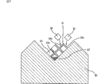
図4(a)は、上記封口処理を行う際に使用する封口装置の一例を模式的に示した断面図であり、(b)は、その一部を示す部分拡大断面図である。
図4に示したように、上記封口処理で用いる封口装置100は、所定のパターンに開口部111aが形成されたマスク111が側面に設置され、その内部が充填材ペースト120で満たされた二組の密閉式の充填材吐出槽110が、マスク111が形成された側面同士を向かい合うように配設されている。
このような封口装置100を用いて上記セラミック乾燥体の封口処理を行うには、まず、セラミック乾燥体40の端面40aと、充填材吐出槽110の側面に形成されたマスク111とが当接するようにセラミック乾燥体40を充填材吐出槽110の間に固定する。
このとき、マスク111の開口部111aとセラミック乾燥体40の貫通孔42とは、ちょうど対向する位置関係となっている。
続いて、充填材吐出槽110に、例えば、モノポンプ等のポンプを用いて一定の圧力を加えて、充填材ペースト120をマスク111の開口部111aより吐出させ、セラミック乾燥体40の貫通孔42の端部に充填材ペースト120を侵入させることで、セラミック乾燥体40の所定の貫通孔42に、充填材となる充填材ペースト120を充填することができる。
なお、上記封口処理で使用する封口装置は、上述したような封口装置100に限定されることはなく、例えば、その内部に攪拌片が配設された開放式の充填材吐出槽を備え、上記攪拌片を上下方向に移動させることにより、上記充填材吐出槽に満たされた充填材ペーストを流動させ、該充填材ペーストの充填を行う方式であってもよい。
上記充填材ペーストとしては、後工程を経て製造される充填材の気孔率が90%以下であり、かつ、セラミック乾燥体40を焼成することで製造される柱状体の気孔率の0.15〜4.0倍となるものであれば特に限定されず、例えば、上記原料ペーストと同様のものを用いることができるが、上記原料ペーストで用いたセラミック粉末に潤滑剤、溶剤、分散剤及びバインダーを添加したものであることが望ましい。上記封口処理の途中で充填材ペースト中のセラミック粒子が沈降することを防止することができるからである。なお、上記充填材ペーストが、上述した条件を外れるようなものであると、本発明のハニカムフィルタにおいて説明したように、後工程を経て製造するハニカムフィルタに、充填材と壁部との接着強度の低下、充填材の強度の低下、充填材と壁部との間に隙間やクラックの発生、及び、充填材や該充填材に接触する部分の壁部にクラックが発生する等の不具合が生じることとなる。
このような充填材ペーストにおいて、上記セラミック粉末は、その平均粒径が大きな粗粉に、その平均粒径が小さな微粉が少量添加されたものであることが望ましい。上記微粉がセラミック粒子同士を接着させるからである。また、上記粗粉の平均粒径の下限は5μmであることが望ましく、10μmであることがより望ましい。また、上記粗粉の平均粒径の上限は100μmであることが望ましく、50μmであることがより望ましい。一方、上記微粉の平均粒径はサブミクロンであることが望ましい。
上記潤滑剤としては特に限定されず、例えば、ポリオキシエチレンアルキルエーテル、ポリオキシプロピレンアルキルエーテル等からなるものを挙げることができる。
このような潤滑剤は、セラミック粉末100重量部に対して0.5〜8重量部添加されることが望ましい。0.5重量部未満であると、充填材ペースト中のセラミック粒子の沈降速度が大きくなり、すぐに分離してしまうことがある。また、充填材ペーストの流路抵抗が高くなるためセラミック乾燥体の貫通孔内に充分に充填材ペーストを進入させることが困難となることがある。一方、8重量部を超えると、セラミック乾燥体を焼成する際の収縮が大きくなりクラックが発生しやすくなる。
上記ポリオキシエチレンアルキルエーテル又はポリオキシプロピレンアルキルエーテルは、アルコールに酸化エチレン又は酸化プロピレンを付加重合させて製造されるものであり、ポリオキシエチレン(ポリオキシプロピレン)の一端の酸素にアルキル基が結合したものである。上記アルキル基としては特に限定されず、例えば、炭素数が3〜22のものを挙げることができる。このアルキル基は、直鎖状のものでも、側鎖を有するものでもよい。
また、上記ポリオキシエチレンアルキルエーテルと、ポリオキシプロピレンアルキルエーテルとは、ポリオキシエチレンとポリオキシプロピレンとからなるブロックコポリマーにアルキル基が結合したものであってもよい。
上記溶剤としては特に限定されず、例えば、ジエチレングリコールモノ−2−エチルヘキシルエーテル等を挙げることができる。
このような溶剤は、セラミック粉末100重量部に対して5〜20重量部添加されることが望ましい。この範囲を外れるとセラミック乾燥体の貫通孔に充填材ペーストを充填することが困難となる。
上記分散剤としては特に限定されず、例えば、リン酸エステル塩からなる界面活性剤を挙げることができる。上記リン酸エステル塩としては、例えば、ポリオキシエチレンアルキルエーテルリン酸塩、ポリオキシエチレンアルキルフェニルエーテルリン酸塩、アルキルリン酸塩等を挙げることができる。
このような分散剤は、セラミック粉末100重量部に対して0.1〜5重量部添加されることが望ましい。0.1重量部未満であると、セラミック粒子を充填材ペースト中に均一に分散させることができないことがあり、一方、5重量部を超えると、充填材ペーストの密度が低下するため、焼成時の収縮量が大きくなってクラック等が発生しやすくなる。
上記バインダーとしては特に限定されず、例えば、(メタ)アクリル酸n−ブチル、(メタ)アクリル酸n−ペンチル、(メタ)アクリル酸n−ヘキシル等の(メタ)アクリル酸エステル系化合物等を挙げることができる。
このようなバインダーは、セラミック粉末100重量部に対して1〜10重量部添加されることが望ましい。1重量部未満であると、セラミック粒子と他の添加剤との結合力を充分に確保することができないことがある。一方、10重量部を超えると、バインダーの量が多くなりすぎるため、焼成工程において収縮量が大きくなってクラック等が発生しやすくなる。
そして、上記充填材ペーストが充填されたセラミック乾燥体に、所定の条件で脱脂、焼成を行うことにより、多孔質セラミックからなり、その全体が一の焼結体から構成されたハニカムフィルタを製造する。
なお、上記セラミック乾燥体の脱脂及び焼成の条件等は、従来から多孔質セラミックからなるハニカムフィルタを製造する際に用いられている条件を適用することができる。
また、本発明のハニカムフィルタの構造が、図2に示したような、多孔質セラミック部材がシール材層を介して複数個結束されて構成されたものである場合、まず、上述したセラミックを主成分とする原料ペーストを用いて押出成形を行い、図3に示した多孔質セラミック部材30のような形状の生成形体を作製する。
なお、上記原料ペーストは、上述した一の焼結体からなるハニカムフィルタにおいて説明した原料ペーストと同様のものを挙げることができる。
次に、上記生成形体を、マイクロ波乾燥機等を用いて乾燥させて乾燥体とした後、該乾燥体の所定の貫通孔に充填材となる充填材ペーストを充填し、上記貫通孔を目封じする封口処理を施す。
なお、上記充填材ペーストは、上述した一の焼結体からなるハニカムフィルタにおいて説明した充填材ペーストと同様のものを挙げることができ、上記封口処理は、充填材ペーストを充填する対象が異なるほかは、上述したハニカムフィルタ10の場合と同様の方法を挙げることができる。
次に、上記封口処理を経た乾燥体に所定の条件で脱脂、焼成を行うことにより、複数の貫通孔が隔壁を隔てて長手方向に並設された多孔質セラミック部材を製造する。
なお、上記生成形体の脱脂及び焼成の条件等は、従来から多孔質セラミック部材がシール材層を介して複数個結束されて構成されたハニカムフィルタを製造する際に用いられている条件等を適用することができる。
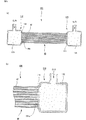
次に、図5に示したように、多孔質セラミック部材30が斜めに傾斜した状態で積み上げることができるように、断面V字形状に構成された台80の上に、多孔質セラミック部材30を傾斜した状態で載置した後、上側を向いた2つの側面30a、30bに、シール材層24となるシール材ペーストを均一な厚さで塗布してシール材ペースト層81を形成し、このシール材ペースト層81の上に、順次他の多孔質セラミック部材30を積層する工程を繰り返し、所定の大きさの角柱状の多孔質セラミック部材30の積層体を作製する。この際、積層体の4隅にあたる多孔質セラミック部材30には、四角柱形状の多孔質セラミック部材を2つに切断して作製した三角柱状の多孔質セラミック部材30cと、三角柱状の多孔質セラミック部材30cと同じ形状の樹脂部材82とを易剥離性の両面テープ等で貼り合わせてなるものを使用し、多孔質セラミック部材30の積層が完了した後に、積層体の4隅を構成する樹脂部材82を全て取り除くことによって、積層体を断面多角柱状にしてもよい。これにより、積層体の外周部を切削加工してセラミックブロックを作製した後に廃棄されることとなる多孔質セラミック部材からなる廃棄物の量を減らすことができる。
上記図5に示した方法以外であっても、断面多角柱状の積層体を作製する方法としては、作製するハニカムフィルタの形状に合わせて、例えば、4隅の多孔質セラミック部材を省略する方法、三角柱状の多孔質セラミック部材を組み合わせる方法等を用いることができる。また、もちろん四角柱状の積層体を作製してもよい。
なお、上記シール材ペーストを構成する材料としては、上述した本発明のハニカムフィルタにおいて説明した通りであるのでここではその説明を省略する。
次に、この多孔質セラミック部材30の積層体を加熱してシール材ペースト層81を乾燥、固化させてシール材層24とし、その後、例えば、ダイヤモンドカッター等を用いて、その外周部を図2に示したような形状に切削することで、セラミックブロック25を作製する。
そして、セラミックブロック25の外周に上記シール材ペーストを用いてシール材層26を形成することで、多孔質セラミック部材がシール材層を介して複数個結束されて構成されたハニカムフィルタを製造することができる。
このようにして製造したハニカムフィルタはいずれも柱状であり、その構造は、多数の貫通孔が壁部を隔てて並設されている。
ただし、ハニカムフィルタが、図1に示したような、その全体が一の焼結体からなる構造である場合、多数の貫通孔を隔てる壁部は、その全体が粒子捕集用フィルタとして機能するのに対し、ハニカムフィルタが、図2に示したような、多孔質セラミック部材がシール材層を介して複数個結束された構造である場合、多数の貫通孔を隔てる壁部は、多孔質セラミック部材を構成する隔壁と、当該多孔質セラミック部材を結束するシール材層とからなるため、その一部、即ち、多孔質セラミック部材のシール材層と接していない隔壁部分が粒子捕集用フィルタとして機能する。
本発明のハニカムフィルタは、エンジン等の内燃機関の排気通路に配設される排気ガス浄化装置に設置されて使用される。なお、本発明のハニカムフィルタでは、捕集して堆積した微粒子を除去する再生処理の方法として、気流により逆洗浄を行う方法が用いられてもよく、それ以外の方法が用いられてもよい。それ以外の方法としては特に限定されるものではないが、例えば、排気ガスを加熱することにより微粒子を燃焼させて除去する方法等が挙げられる。
図6は、本発明のハニカムフィルタが設置された排気ガス浄化装置の一例を模式的に示した断面図である。なお、図6に示す本発明のハニカムフィルタでは、捕集して堆積した微粒子を除去する再生処理の方法として、上述した加熱により微粒子を除去する方法が用いられている。
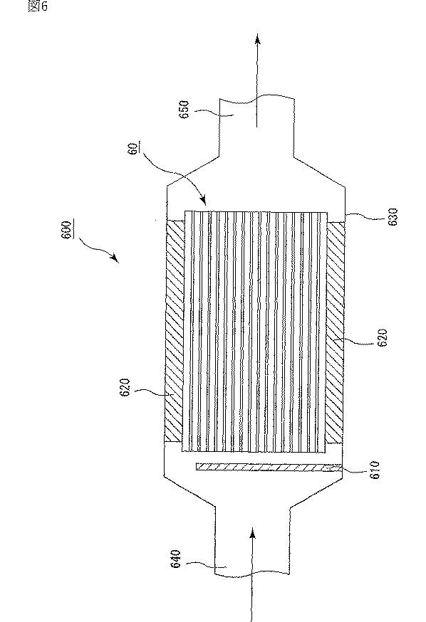
図6に示したように、排気ガス浄化装置600は、主に、本発明のハニカムフィルタ60、ハニカムフィルタ60の外方を覆うケーシング630、ハニカムフィルタ60とケーシング630との間に配置された保持シール材620、及び、ハニカムフィルタ60の排気ガス流入側に設けられた加熱手段610から構成されており、ケーシング630の排気ガスが導入される側の端部には、エンジン等の内燃機関に連結された導入管640が接続されており、ケーシング630の他端部には、外部に連結された排出管650が接続されている。なお、図6中、矢印は排気ガスの流れを示している。
また、図6において、ハニカムフィルタ60は、図1に示したハニカムフィルタ10であってもよく、図2に示したハニカムフィルタ20であってもよい。
このような構成からなる排気ガス浄化装置600では、エンジン等の内燃機関から排出された排気ガスは、導入管640を通ってケーシング630内に導入され、ハニカムフィルタ60の貫通孔から壁部(隔壁)を通過してこの壁部(隔壁)でパティキュレートが捕集されて浄化された後、排出管650を通って外部へ排出されることとなる。
そして、ハニカムフィルタ60の壁部(隔壁)に大量のパティキュレートが堆積し、圧損が高くなると、ハニカムフィルタ60の再生処理が行われる。
上記再生処理では、加熱手段610を用いて加熱されたガスをハニカムフィルタ60の貫通孔の内部へ流入させることで、ハニカムフィルタ60を加熱し、壁部(隔壁)に堆積したパティキュレートを燃焼除去するのである。
保持シール材620を構成する材料としては特に限定されず、例えば、結晶質アルミナ繊維、アルミナ−シリカ繊維、シリカ繊維等の無機繊維や、これらの無機繊維を一種以上含む繊維等を挙げることができる。
また、保持シール材620には、アルミナ及び/又はシリカが含有されていることが望ましい。保持シール材620の耐熱性及び耐久性が優れたものとなるからである。特に、保持シール材620は、50重量%以上のアルミナが含有されていることが望ましい。900〜950℃程度の高温下であっても、弾性力が高くなり、ハニカムフィルタ60を保持する力が高まるからである。
また、保持シール材620には、ニードルパンチ処理が施されていることが望ましい。保持シール材620を構成する繊維同士が絡み合い、弾性力が高くなり、ハニカムフィルタ60を保持する力が向上するからである。
保持シール材620の形状としては、ハニカムフィルタ60の外周に被覆することができる形状であれば特に限定されず、任意の形状を挙げることができるが、矩形状の基材部の一の辺に凸部が形成され、該一の辺に対向する辺に凹部が形成され、ハニカムフィルタ60の外周に被覆した際、上記凸部と凹部とがちょうど嵌合されるような形状であることが望ましい。ハニカムフィルタ60の外周に被覆した保持シール材620にズレが発生しにくくなるからである。
ケーシング630の材質としては特に限定されず、例えば、ステンレス等を挙げることができる。
また、その形状は特に限定されず、図7(a)に示したケーシング71のような筒状であってもよく、(b)に示したケーシング72のような筒をその軸方向に2分割した2分割シェル状であってもよい。
また、ケーシング630の大きさは、ハニカムフィルタ60を、保持シール材620を介して内部に設置することができるように適宜調整される。そして、図6に示したように、ケーシング630の一端面には、排気ガスを導入させる導入管640が接続され、他端面には、排気ガスを排出させる排出管650が接続されるようになっている。
加熱手段610は、上述した通り、ハニカムフィルタ60の再生処理において、ハニカムフィルタ60の壁部(隔壁)に堆積したパティキュレートを燃焼除去させるために、貫通孔の内部に流入させるガスを加熱するために設けられており、このような加熱手段610としては特に限定されず、例えば、電気ヒータやバーナー等を挙げることができる。
なお、上記貫通孔の内部に流入させるガスとしては、例えば、排気ガスや空気等を挙げることができる。
また、このような排気ガス浄化装置では、図6に示したように、ハニカムフィルタ60の排気ガス流入側に設けた加熱手段610によりハニカムフィルタ60を加熱するような方式であってもよく、例えば、ハニカムフィルタに酸化触媒を担持させ、この酸化触媒を担持させたハニカムフィルタに炭化水素を流入させることで、上記ハニカムフィルタを発熱させる方式であってもよく、また、ハニカムフィルタの排気ガス流入側に酸化触媒を配置し、該酸化触媒に炭化水素を供給することで発熱させ、上記ハニカムフィルタを加熱する方式であってもよい。
酸化触媒と炭化水素との反応は、発熱反応であるので、この反応時に発生する多量の熱を利用することにより、排気ガスの浄化と並行して、ハニカムフィルタの再生を行うことができる。
このような本発明のハニカムフィルタを設置した排気ガス浄化装置を製造するには、まず、本発明のハニカムフィルタの外周に被覆する保持シール材を作製する。
上記保持シール材を作製するには、まず、結晶質アルミナ繊維、アルミナ−シリカ繊維、シリカ繊維等の無機繊維や、これらの無機繊維を一種以上含む繊維等を用いて無機質マット状物(ウェッブ)を形成する。
また、上記無機質マット状物を形成する方法としては特に限定されず、例えば、上述した繊維等を、接着剤を含んだ溶液中に分散させ、紙を作る抄紙機等を利用して無機質マット状物を形成する方法等を挙げることができる。
また、上記無機質マット状物にニードルパンチ処理を施すことが望ましい。ニードルパンチ処理を施すことにより、繊維同士を絡み合わせることができ、弾性力が高く、ハニカムフィルタを保持する力に優れる保持シール材を作製することができるからである。
その後、上記無機質マット状物に切断加工を施して、例えば、上述したような矩形状の基材部の一の辺に凸部が設けられ、該一の辺に対向する辺に凹部が設けられたような形状の保持シール材を作製する。
次に、本発明のハニカムフィルタの外周に上記保持シール材を被覆し、該保持シール材を固定する。
上記保持シール材を固定する手段としては特に限定されず、例えば、接着剤で貼着したり、紐状体で縛る手段等を挙げることができる。また、特別な手段で固定をせず、ハニカムフィルタに被覆しただけの状態で、次の工程に移行しても差し支えない。なお、上記紐状体は、熱で分解する材料であってもよい。ケーシング内にハニカムフィルタを設置した後であれば、紐状体が熱により分解してもハニカムフィルタはケーシング内に設置されているので、保持シール材が剥がれてしまうことはないからである。
次に、上記工程を経たハニカムフィルタをケーシング内に設置する。
なお、上記ケーシングの材料、形状及び構成等については、上述した通りであるのでここでは、その説明を省略する。
ハニカムフィルタを、ケーシング内に設置する方法としては、上記ケーシングが筒状のケーシング71である場合(図7(a))、例えば、保持シール材が被覆されたハニカムフィルタをその一端面から押し込み、所定の位置に設置した後、導入管、配管及び排出管等と接続するための端面を、ケーシング71の両端部に形成する方法を挙げることができる。なお、ケーシング71は有底の筒状であってもよい。
この際、固定したハニカムフィルタが容易に移動しないように、かなりの力を加えた状態で、ようやく押し込むことができる程度に、保持シール材の厚さ、ハニカムフィルタの大きさ、ケーシング71の大きさ等を調整する必要がある。
また、図7(b)に示したように、上記ケーシングの形状が2分割シェル状のケーシング72である場合には、例えば、ハニカムフィルタを半筒状の下部シェル72b内の所定箇所に設置した後、上部固定部73に形成した貫通孔73aと、下部固定部74に形成した貫通孔74aとがちょうど重なるように、半筒状の上部シェル72aを下部シェル72bの上に載置する。そして、ボルト75を貫通孔73a、74aに挿通しナット等で固定することで、上部シェル72aと下部シェル72bとを固定する。そして、導入管、配管及び排出管等と接続するための開口を有する端面を、ケーシング72の両端部に形成する方法を挙げることができる。この場合にも、固定したハニカムフィルタが移動しないように、保持シール材の厚さ、ハニカムフィルタの大きさ、ケーシング72の大きさ等を調整する必要がある。
この2分割シェル状のケーシング72は、内部に設置したハニカムフィルタの取替えが、筒状のケーシング71よりも容易である。
次に、本発明のハニカムフィルタの再生処理を行う際に、ハニカムフィルタの貫通孔内に流入させるガスを加熱するための加熱手段を設ける。
上記加熱手段としては特に限定されず、例えば、電気ヒータやバーナー等を挙げることがでる。
また、上記加熱手段は、通常、ケーシング内に設置したハニカムフィルタの排気ガス流入側の端面近傍に設ける。
なお、上記排気ガス浄化装置において説明した通り、上述したような加熱手段を設けずに、本発明のハニカムフィルタに酸化触媒を担持させてもよく、ハニカムフィルタの排気ガス流入側に酸化触媒を配置してもよい。
次に、本発明のハニカムフィルタと加熱手段とを内部に設置したケーシングを内燃機関の排気通路に接続することで本発明のハニカムフィルタを設置した排気ガス浄化装置を製造することができる。
具体的には、上記ケーシングの加熱手段が設けられた側の端面をエンジン等の内燃機関に連結された導入管に接続し、他端面を外部へ連結された排出管に接続する。
発明を実施するための最良の形態
以下に実施例を掲げて本発明を更に詳しく説明するが、本発明はこれら実施例のみに限定されるものではない。
(実施例1)
(1)平均粒径10μmのα型炭化珪素粉末60重量%と、平均粒径0.5μmのβ型炭化珪素粉末40重量%とを湿式混合し、得られた混合物100重量部に対して、有機バインダー(メチルセルロース)を5重量部、水を10重量部加えて混練して原料ペーストを調製した。
次に、上記原料ペーストを押出成形機に充填し、押出速度10cm/分にて図3に示した多孔質セラミック部材30と略同形状のセラミック成形体を作製し、上記セラミック成形体を、マイクロ波乾燥機を用いて乾燥させてセラミック乾燥体とした。
次に、平均粒径10μmのα型炭化珪素粉末60重量%と、平均粒径0.5μmのβ型炭化珪素粉末40重量%とを混合し、得られた混合物100重量部に、ポリオキシエチレンモノブチルエーテルからなる潤滑剤(日本油脂社製、商品名:ユニルーブ)を2重量部、ジエチレングリコールモノ−2−エチルヘキシルエーテルからなる溶剤(協和発酵社製、商品名:OX−20)を8重量部、リン酸エステル系化合物からなる分散剤(第一工業製薬社製、商品名:プライサーフ)を1.1重量部、メタクリル酸n−ブチルをOX−20で溶解したバインダー(東栄化成社製、商品名:バインダーD)を4重量部、及び、アクリル粒子を0.15重量部配合して均一に混合することにより充填材ペーストを調製した。
この充填材ペーストを図4に示した封口装置100の充填材吐出槽110に充填し、上記工程で作製したセラミック乾燥体を所定の位置に移動、固定し、充填材吐出槽110を移動させることにより、マスク111をセラミック乾燥体の端面に当接させた。このとき、マスク111の開口部111aとセラミック乾燥体の貫通孔とは、ちょうど対向する位置関係となっている。
続いて、モノポンプを用いて充填材吐出槽110に所定の圧力を印加することにより、充填材ペーストをマスク111の開口部111aより吐出させ、セラミック乾燥体の貫通孔の端部に進入させる封口処理を行った。
そして、上記封口処理を行ったセラミック乾燥体を、再びマイクロ波乾燥機を用いて乾燥させた後、400℃で脱脂し、常圧のアルゴン雰囲気下2200℃、4時間で焼成を行うことにより、図2に示したような、その大きさが33mm×33mm×300mmで、貫通孔の数が31個/cm2、隔壁の厚さが0.3mmの炭化珪素焼結体からなる多孔質セラミック部材を製造した。
(2)繊維長0.2mmのアルミナファイバー19.6重量%、平均粒径0.6μmの炭化珪素粒子67.8重量%、シリカゾル10.1重量%及びカルボキシメチルセルロース2.5重量%を含む耐熱性のシール材ペーストを用いて上記多孔質セラミック部材を、図5を用いて説明した方法により多数結束させ、続いて、ダイヤモンドカッターを用いて切断することにより、図2に示したような直径が165mmで円柱形状のセラミックブロックを作製した。
次に、無機繊維としてアルミナシリケートからなるセラミックファイバー(ショット含有率:3%、繊維長:0.1〜100mm)23.3重量%、無機粒子として平均粒径0.3μmの炭化珪素粉末30.2重量%、無機バインダーとしてシリカゾル(ゾル中のSiO2の含有率:30重量%)7重量%、有機バインダーとしてカルボキシメチルセルロース0.5重量%及び水39重量%を混合、混練してシール材ペーストを調製した。
次に、上記シール材ペーストを用いて、上記セラミックブロックの外周部に厚さ1.0mmのシール材ペースト層を形成した。そして、このシール材ペースト層を120℃で乾燥して、図1に示したような円柱形状のハニカムフィルタを製造した。
このようにして製造したハニカムフィルタにおいて、充填材を除いた柱状体の平均気孔径は10μm、気孔率は20%であり、上記充填材の気孔率は3%であり、この充填材の気孔率は、上記柱状体の気孔率の0.15倍であった。
(実施例2)
平均粒径10μmのα型炭化珪素粉末60重量%と、平均粒径0.5μmのβ型炭化珪素粉末40重量%とを湿式混合し、得られた混合物100重量部に、ユニルーブを2重量部、OX−20を8重量部、プライサーフを1.1重量部、バインダーDを4重量部、及び、アクリル粒子を0.2重量部配合して均一に混合することにより充填材ペーストを調製し、この充填材ペーストを用いたほかは、実施例1と同様にしてハニカムフィルタを製造した。
このようにして製造した実施例2に係るハニカムフィルタにおいて、充填材を除いた柱状体の平均気孔径は10μm、気孔率は20%であり、充填材の気孔率は5%であり、この充填材の気孔率は、上記柱状体の気孔率の0.25倍であった。
(実施例3)
平均粒径10μmのα型炭化珪素粉末60重量%と、平均粒径0.5μmのβ型炭化珪素粉末40重量%とを湿式混合し、得られた混合物100重量部に、ユニルーブを4重量部、OX−20を11重量部、プライサーフを2重量部、バインダーDを5重量部、及び、アクリル粒子を10重量部配合して均一に混合することにより充填材ペーストを調製し、この充填材ペーストを用いたほかは、実施例1と同様にしてハニカムフィルタを製造した。
このようにして製造した実施例3に係るハニカムフィルタにおいて、充填材を除いた柱状体の平均気孔径は10μm、気孔率は20%であり、充填材の気孔率は30%であり、この充填材の気孔率は、上記柱状体の気孔率の1.5倍であった。
(実施例4)
平均粒径10μmのα型炭化珪素粉末70重量%と、平均粒径0.5μmのβ型炭化珪素粉末30重量%とを湿式混合し、得られた混合物100重量部に、ユニルーブを10重量部、OX−20を15重量部、プライサーフを3重量部、バインダーDを8重量部、及び、アクリル粒子を25重量部配合して均一に混合することにより充填材ペーストを調製し、この充填材ペーストを用いたほかは、実施例1と同様にしてハニカムフィルタを製造した。
このようにして製造した実施例3に係るハニカムフィルタにおいて、充填材を除いた柱状体の平均気孔径は10μm、気孔率は20%であり、充填材の気孔率は80%であり、この充填材の気孔率は、上記柱状体の気孔率の4.0倍であった。
(比較例1)
平均粒径10μmのα型炭化珪素粉末60重量%と、平均粒径0.5μmのβ型炭化珪素粉末40重量%とを混合し、得られた組成物100重量部に、ユニルーブを2重量部、OX−20を8重量部、プライサーフを1.1重量部、バインダーDを4重量部、及び、アクリル粒子を0.1重量部配合して均一に混合することにより充填材ペーストを調製し、この充填材ペーストを用いたほかは、実施例1と同様にしてハニカムフィルタを製造した。
このようにして製造した比較例1に係るハニカムフィルタにおいて、充填材を除いた柱状体の平均気孔径は10μm、気孔率は20%であり、充填材の気孔率は2%であり、この充填材の気孔率は、上記柱状体の気孔率の0.1倍であった。
(比較例2)
平均粒径10μmのα型炭化珪素粉末70重量%と、平均粒径0.5μmのβ型炭化珪素粉末30重量%とを混合し、得られた組成物100重量部に、ユニルーブを10重量部、OX−20を15重量部、プライサーフを3重量部、バインダーDを8重量部、及び、アクリル粒子を28重量部配合して均一に混合することにより充填材ペーストを調製し、この充填材ペーストを用いたほかは、実施例1と同様にしてハニカムフィルタを製造した。
このようにして製造した比較例2に係るハニカムフィルタにおいて、充填材を除いた柱状体の平均気孔径は10μm、気孔率は20%であり、充填材の気孔率は85%であり、この充填材の気孔率は、上記柱状体の気孔率の4.25倍であった。
(実施例5)
原料ペースト及び充填材ペーストを以下の通りとしたほかは、実施例1と同様にハニカムフィルタを製造した。
<原料ペーストの調製>
平均粒径10μmのα型炭化珪素粉末70重量%と、平均粒径0.5μmのβ型炭化珪素粉末30重量%とを湿式混合し、得られた混合物100重量部に対して、有機バインダー(メチルセルロース)を13重量部、水を20重量部、及び、平均粒径10μmのアクリル粒子を70重量部加えて混練して原料ペーストを調製した。
<充填材ペーストの調製>
平均粒径10μmのα型炭化珪素粉末60重量%と、平均粒径0.5μmのβ型炭化珪素粉末40重量%とを混合し、得られた組成物100重量部に、ユニルーブを2.2重量部、OX−20を9重量部、プライサーフを2重量部、バインダーDを4重量部、及び、アクリル粒子を0.3重量部配合して均一に混合することにより充填材ペーストを調製した。
このような原料ペースト及び充填材ペーストを用いて製造した実施例5に係るハニカムフィルタにおいて、充填材を除いた柱状体の平均気孔径は10μm、気孔率は50%であり、充填材の気孔率は7.5%であり、この充填材の気孔率は、上記柱状体の気孔率の0.15倍であった。
(実施例6)
平均粒径10μmのα型炭化珪素粉末60重量%と、平均粒径0.5μmのβ型炭化珪素粉末40重量%とを混合し、得られた組成物100重量部に、ユニルーブを4重量部、OX−20を11重量部、プライサーフを2重量部、バインダーDを5重量部、及び、アクリル粒子を5重量部配合して均一に混合することにより充填材ペーストを調製し、この充填材ペーストを用いたほかは、実施例5と同様にしてハニカムフィルタを製造した。
このようにして製造した実施例6に係るハニカムフィルタにおいて、充填材を除いた柱状体の平均気孔径は10μm、気孔率は50%であり、充填材の気孔率は12%であり、この充填材の気孔率は、上記柱状体の気孔率の0.24倍であった。
(実施例7)
平均粒径10μmのα型炭化珪素粉末70重量%と、平均粒径0.5μmのβ型炭化珪素粉末30重量%とを混合し、得られた組成物100重量部に、ユニルーブを10重量部、OX−20を15重量部、プライサーフを3重量部、バインダーDを8重量部、及び、アクリル粒子を23重量部配合して均一に混合することにより充填材ペーストを調製し、この充填材ペーストを用いたほかは、実施例5と同様にしてハニカムフィルタを製造した。
このようにして製造した実施例7に係るハニカムフィルタにおいて、充填材を除いた柱状体の平均気孔径は10μm、気孔率は50%であり、充填材の気孔率は75%であり、この充填材の気孔率は、上記柱状体の気孔率の1.5倍であった。
(実施例8)
平均粒径10μmのα型炭化珪素粉末70重量%と、平均粒径0.5μmのβ型炭化珪素粉末30重量%とを混合し、得られた組成物100重量部に、ユニルーブを10重量部、OX−20を15重量部、プライサーフを3重量部、バインダーDを8重量部、及び、アクリル粒子を30重量部配合して均一に混合することにより充填材ペーストを調製し、この充填材ペーストを用いたほかは、実施例5と同様にしてハニカムフィルタを製造した。
このようにして製造した実施例8に係るハニカムフィルタにおいて、充填材を除いた柱状体の平均気孔径は10μm、気孔率は50%であり、充填材の気孔率は90%であり、この充填材の気孔率は、上記柱状体の気孔率の1.8倍であった。
(比較例3)
平均粒径10μmのα型炭化珪素粉末60重量%と、平均粒径0.5μmのβ型炭化珪素粉末40重量%とを混合し、得られた組成物100重量部に、ユニルーブを2重量部、OX−20を8重量部、プライサーフを1.1重量部、バインダーDを4重量部、及び、アクリル粒子を0.2重量部配合して均一に混合することにより充填材ペーストを調製し、この充填材ペーストを用いたほかは、実施例5と同様にしてハニカムフィルタを製造した。
このようにして製造した比較例3に係るハニカムフィルタにおいて、充填材を除いた柱状体の平均気孔径は10μm、気孔率は50%であり、充填材の気孔率は5%であり、この充填材の気孔率は、上記柱状体の気孔率の0.1倍であった。
(比較例4)
平均粒径10μmのα型炭化珪素粉末70重量%と、平均粒径0.5μmのβ型炭化珪素粉末30重量%とを混合し、得られた組成物100重量部に、ユニルーブを10重量部、OX−20を15重量部、プライサーフを3重量部、バインダーDを8.3重量部、及び、アクリル粒子を33重量部配合して均一に混合することにより充填材ペーストを調製し、この充填材ペーストを用いたほかは、実施例5と同様にしてハニカムフィルタを製造した。
このようにして製造した比較例4に係るハニカムフィルタにおいて、充填材を除いた柱状体の平均気孔径は10μm、気孔率は50%であり、充填材の気孔率は92%であり、この充填材の気孔率は、上記柱状体の気孔率の1.84倍であった。
(実施例9)
原料ペースト及び充填材ペーストを以下の通りとしたほかは、実施例1と同様にハニカムフィルタを製造した。
<原料ペーストの調製>
平均粒径10μmのα型炭化珪素粉末80重量%と、平均粒径0.5μmのβ型炭化珪素粉末20重量%とを湿式混合し、得られた混合物100重量部に対して、有機バインダー(メチルセルロース)を30重量部、水を35重量部、及び、平均粒径10μmのアクリル粒子を80重量部加えて混練して原料ペーストを調製した。
<充填材ペーストの調製>
平均粒径10μmのα型炭化珪素粉末60重量%と、平均粒径0.5μmのβ型炭化珪素粉末40重量%とを混合し、得られた組成物100重量部に、ユニルーブを4重量部、OX−20を11重量部、プライサーフを2重量部、バインダーDを5重量部、及び、アクリル粒子5重量部を配合して均一に混合することにより充填材ペーストを調製した。
このような原料ペースト及び充填材ペーストを用いて製造した実施例9に係るハニカムフィルタにおいて、充填材を除いた柱状体の平均気孔径は10μm、気孔率は80%であり、充填材の気孔率は12%であり、この充填材の気孔率は、上記柱状体の気孔率の0.15倍であった。
(実施例10)
平均粒径10μmのα型炭化珪素粉末60重量%と、平均粒径0.5μmのβ型炭化珪素粉末40重量%とを混合し、得られた組成物100重量部に、ユニルーブを4重量部、OX−20を11重量部、プライサーフを2重量部、バインダーDを5重量部、及び、アクリル粒子を7重量部配合して均一に混合することにより充填材ペーストを調製し、この充填材ペーストを用いたほかは、実施例9と同様にしてハニカムフィルタを製造した。
このようにして製造した実施例10に係るハニカムフィルタにおいて、充填材を除いた柱状体の平均気孔径は10μm、気孔率は80%であり、充填材の気孔率は20%であり、この充填材の気孔率は、上記柱状体の気孔率の0.25倍であった。
(実施例11)
平均粒径10μmのα型炭化珪素粉末70重量%と、平均粒径0.5μmのβ型炭化珪素粉末30重量%とを混合し、得られた組成物100重量部に、ユニルーブを10重量部、OX−20を15重量部、プライサーフを3重量部、バインダーDを8重量部、及び、アクリル粒子30重量部を配合して均一に混合することにより充填材ペーストを調製し、この充填材ペーストを用いたほかは、実施例9と同様にしてハニカムフィルタを製造した。
このようにして製造した実施例11に係るハニカムフィルタにおいて、充填材を除いた柱状体の平均気孔径は10μm、気孔率は80%であり、充填材の気孔率は90%であり、この充填材の気孔率は、上記柱状体の気孔率の1.125倍であった。
(比較例5)
平均粒径10μmのα型炭化珪素粉末60重量%と、平均粒径0.5μmのβ型炭化珪素粉末40重量%とを混合し、得られた組成物100重量部に、ユニルーブを2.2重量部、OX−20を9重量部、プライサーフを2重量部、バインダーDを4重量部、及び、アクリル粒子を0.35重量部配合して均一に混合することにより充填材ペーストを調製し、この充填材ペーストを用いたほかは、実施例9と同様にしてハニカムフィルタを製造した。
このようにして製造した比較例5に係るハニカムフィルタにおいて、充填材を除いた柱状体の平均気孔径は10μm、気孔率は80%であり、充填材の気孔率は10%であり、この充填材の気孔率は、上記柱状体の気孔率の0.125倍であった。
(比較例6)
平均粒径10μmのα型炭化珪素粉末70重量%と、平均粒径0.5μmのβ型炭化珪素粉末30重量%とを混合し、得られた組成物100重量部に、ユニルーブを10重量部、OX−20を15重量部、プライサーフを3重量部、バインダーDを8.3重量部、及び、アクリル粒子を33重量部配合して均一に混合することにより充填材ペーストを調製し、この充填材ペーストを用いたほかは、実施例9と同様にしてハニカムフィルタを製造した。
このようにして製造した比較例6に係るハニカムフィルタにおいて、充填材を除いた柱状体の平均気孔径は10μm、気孔率は80%であり、充填材の気孔率は92%であり、この充填材の気孔率は、上記柱状体の気孔率の1.15倍であった。
このようにして製造した実施例1〜11、及び、比較例1〜6に係るハニカムフィルタの充填材の気孔率(%)、柱状体の気孔率(%)、及び、上記充填材の気孔率が上記柱状体の気孔率の何倍であるかを下記表1にまとめる。
また、実施例1〜11、及び、比較例1〜6に係るハニカムフィルタを焼成した後の充填材と隔壁との間に隙間が形成されているか否か、及び、充填材や該充填材に接触する部分の隔壁にクラックが発生していないか否かを確認し、上記隙間やクラックの発生していなかったハニカムフィルタについて、耐久性試験として、各実施例、及び、比較例に係るハニカムフィルタをエンジンの排気通路に配設した図6に示したような排気ガス浄化装置に設置し、上記エンジンを回転数3000min−1、トルク50Nmで10時間運転して排気ガスの浄化を行った。そして、上記耐久性試験を行った後、各ハニカムフィルタを取り出し、目視によりクラックの有無等を確認した。さらに、上記耐久試験後に、クラックが発生していなかったハニカムフィルタについて、上記耐久試験を300回繰り返すヒートサイクル試験を行い、各ハニカムフィルタを取り出し、目視によりクラックの有無等を確認した。
結果を下記表1に示す。
一方、比較例1、3、5に係るハニカムフィルタでは、焼成後の充填材と隔壁との間に隙間やクラック等は観察されなかったが、耐久試験後の充填材や、該充填材に接触する隔壁にクラックが観察された。また、比較例2に係るハニカムフィルタでは、焼成後の充填材と隔壁との間に隙間が観察され、比較例4、6に係るハニカムフィルタでは、焼成後の充填材にクラックが観察された。
実施例1〜11に係るハニカムフィルタの評価試験の結果より、柱状体の気孔率が20〜80%であり、充填材の気孔率が90%以下であり、かつ、柱状体の気孔率の0.15〜4.0倍であるハニカムフィルタは、焼成後や加熱時に、充填材と隔壁との間に隙間が形成されたり、充填材や、該充填材に接触する部分の隔壁にクラックが発生したりすることがないが、実施例1、4、5、8及び9に係るハニカムフィルタの評価試験の結果より、充填材の気孔率が柱状体の気孔率の0.25倍未満であるか、又は、1.5倍を超えるものであると、長期間繰り返し使用すると、充填材や、該充填材に接触する部分の隔壁にクラックが発生することがある。
また、比較例1、3及び5に係るハニカムフィルタの結果より、充填材の気孔率が柱状体の気孔率の0.15倍未満であると、例え、焼成後の充填材や該充填材に接触する部分の隔壁にクラックが発生していなくても、柱状体の熱膨張率と、充填材の熱膨張率との差が大きくなり、高温の排気ガスにより柱状体及び充填材が加熱されると、両者の間に熱応力が蓄積され、充填材や該充填材に接触する部分の隔壁にクラックが発生してしまう。
また、比較例2に係るハニカムフィルタの結果より、充填材の気孔率が柱状体の気孔率の4.0倍を超えると、焼成後の充填材と該充填材に接触する部分の隔壁との間に隙間が発生してしまう。
さらに、比較例4、6に係るハニカムフィルタの結果より、充填材の気孔率が90%を超えるものであると、例え、上記充填材の気孔率が柱状体の気孔率の0.15〜4.0倍であったとしても、充填材の強度が低下し、焼成時に充填材や該充填材に接触する部分の隔壁にクラックが発生してしまう。
このような比較例1〜6に係るハニカムフィルタは、いずれも、フィルタとして充分に機能することができないものであった。
(実施例12)
(1)実施例1と同様にして、充填材を除いた柱状体の平均気孔径が10μm、気孔率が20%であり、上記充填材の気孔率が3%であり、この充填材の気孔率が上記柱状体の気孔率の0.15倍であるハニカムフィルタを製造した。
(2)5μm以下に粉砕したγ−Al2O3粉末を1,3−ブタンジオール中に投入し、60℃で5時間攪拌することによりアルミナを3重量%含有するスラリー状の1,3−ブタンジオール溶液を調製した。この1,3−ブタンジオール溶液中に上記ハニカムフィルタを浸漬した後、150℃で2時間、400℃で2時間、700℃で8時間加熱して、ハニカムフィルタ(充填材を除いた柱状体、及び、充填材)の表面に触媒担持膜となるアルミナ層を1g/Lの割合で形成した。
白金濃度4.53重量%のジニトロジアンミン白金硝酸([Pt(NH3)2(NO2)2]HNO3)を蒸留水で希釈し、吸水量28.0g/Lの上記ハニカムフィルタにPtが2g/Lとなるように浸漬した後、110℃で2時間、窒素雰囲気中、500℃で1時間加熱して、表面に白金触媒を担持させたハニカムフィルタを製造した。
表面に白金触媒を担持させたハニカムフィルタにおいて、充填材を除いた柱状体の平均気孔径は10μm、気孔率は20%であり、上記充填材の気孔率は3%であり、この充填材の気孔率は、上記柱状体の気孔率の0.15倍であった。
(実施例13)
(1)実施例2と同様にして、充填材を除いた柱状体の平均気孔径が10μm、気孔率が20%であり、上記充填材の気孔率が5%であり、この充填材の気孔率が上記柱状体の気孔率の0.25倍であるハニカムフィルタを製造した。
(2)実施例12と同様にして、ハニカムフィルタ(充填材を除いた柱状体、及び、充填材)の表面に触媒担持膜となるアルミナ層を1g/Lの割合で形成し、表面に白金触媒を担持させたハニカムフィルタを製造した。
表面に白金触媒を担持させたハニカムフィルタにおいて、充填材を除いた柱状体の平均気孔径は10μm、気孔率は20%であり、上記充填材の気孔率は5%であり、この充填材の気孔率は、上記柱状体の気孔率の0.25倍であった。
(実施例14)
(1)平均粒径10μmのα型炭化珪素粉末60重量%と、平均粒径0.5μmのβ型炭化珪素粉末40重量%とを湿式混合し、得られた混合物100重量部に、ユニルーブを2重量部、OX−20を8.5重量部、プライサーフを1.3重量部、バインダーDを4重量部、及び、アクリル粒子を0.25重量部配合して均一に混合することにより充填材ペーストを調製し、この充填材ペーストを用いたほかは、実施例1と同様にしてハニカムフィルタを製造した。
このようにして製造したハニカムフィルタにおいて、充填材を除いた柱状体の平均気孔径は10μm、気孔率は20%であり、充填材の気孔率は6%であり、この充填材の気孔率は、上記柱状体の気孔率の0.30倍であった。
(2)実施例12と同様にして、ハニカムフィルタ(充填材を除いた柱状体、及び、充填材)の表面に触媒担持膜となるアルミナ層を1g/Lの割合で形成し、表面に白金触媒を担持させたハニカムフィルタを製造した。
表面に白金触媒を担持させたハニカムフィルタにおいて、充填材を除いた柱状体の平均気孔径は10μm、気孔率は20%であり、上記充填材の気孔率は6%であり、この充填材の気孔率は、上記柱状体の気孔率の0.30倍であった。
(実施例15)
(1)実施例3と同様にして、充填材を除いた柱状体の平均気孔径が10μm、気孔率が20%であり、上記充填材の気孔率が30%であり、この充填材の気孔率が上記柱状体の気孔率の1.50倍であるハニカムフィルタを製造した。
(2)5μm以下に粉砕したγ−Al2O3粉末を1,3−ブタンジオール中に投入し、60℃で5時間攪拌することによりアルミナを3重量%含有するスラリー状の1,3−ブタンジオール溶液を調製し、この1,3−ブタンジオール溶液中に上記ハニカムフィルタを浸漬した。同様に、γ−Al2O3粉末を1,3−ブタンジオール中に投入し、60℃で5時間攪拌することによりアルミナを20重量%含有するスラリー状の1,3−ブタンジオール溶液を調製し、この1,3−ブタンジオール溶液をハニカムフィルタの充填材部分に注入した。次いで、150℃で2時間、400℃で2時間、700℃で8時間加熱することにより、ハニカムフィルタの充填材を除いた柱状体の表面に触媒担持膜となるアルミナ層を1g/Lの割合で、ハニカムフィルタの充填材の表面にアルミナ層を20g/Lの割合で形成した。
白金濃度4.53重量%のジニトロジアンミン白金硝酸([Pt(NH3)2(NO2)2]HNO3)を蒸留水で希釈し、吸水量28.0g/Lの上記多孔質セラミック部材にPtが2g/Lとなるように浸漬した後、110℃で2時間、窒素雰囲気中、500℃で1時間加熱して、表面に白金触媒を担持させたハニカムフィルタを製造した。
表面に白金触媒を担持させたハニカムフィルタにおいて、充填材を除いた柱状体の平均気孔径は10μm、気孔率は20%であり、上記充填材の気孔率は24%であり、この充填材の気孔率は、上記柱状体の気孔率の1.20倍であった。
(実施例16)
(1)実施例3と同様にして、充填材を除いた柱状体の平均気孔径が10μm、気孔率が20%であり、上記充填材の気孔率が30%であり、この充填材の気孔率が上記柱状体の気孔率の1.50倍であるハニカムフィルタを製造した。
(2)実施例12と同様にして、ハニカムフィルタ(充填材を除いた柱状体、及び、充填材)の表面に触媒担持膜となるアルミナ層を1g/Lの割合で形成し、表面に白金触媒を担持させたハニカムフィルタを製造した。
表面に白金触媒を担持させたハニカムフィルタにおいて、充填材を除いた柱状体の平均気孔径は10μm、気孔率は20%であり、上記充填材の気孔率は30%であり、この充填材の気孔率は、上記柱状体の気孔率の1.50倍であった。
(実施例17)
(1)実施例4と同様にして、充填材を除いた柱状体の平均気孔径が10μm、気孔率が20%であり、上記充填材の気孔率が80%であり、この充填材の気孔率が上記柱状体の気孔率の4.00倍であるハニカムフィルタを製造した。
(2)実施例12と同様にして、ハニカムフィルタ(充填材を除いた柱状体、及び、充填材)の表面に触媒担持膜となるアルミナ層を1g/Lの割合で形成し、表面に白金触媒を担持させたハニカムフィルタを製造した。
表面に白金触媒を担持させたハニカムフィルタにおいて、充填材を除いた柱状体の平均気孔径は10μm、気孔率は20%であり、上記充填材の気孔率は80%であり、この充填材の気孔率は、上記柱状体の気孔率の4.00倍であった。
(実施例18)
(1)実施例5と同様にして、充填材を除いた柱状体の平均気孔径が10μm、気孔率が50%であり、上記充填材の気孔率が7.5%であり、この充填材の気孔率が上記柱状体の気孔率の0.15倍であるハニカムフィルタを製造した。
(2)実施例12と同様にして、ハニカムフィルタ(充填材を除いた柱状体、及び、充填材)の表面に触媒担持膜となるアルミナ層を1g/Lの割合で形成し、表面に白金触媒を担持させたハニカムフィルタを製造した。
表面に白金触媒を担持させたハニカムフィルタにおいて、充填材を除いた柱状体の平均気孔径は10μm、気孔率は50%であり、上記充填材の気孔率は7.5%であり、この充填材の気孔率は、上記柱状体の気孔率の0.15倍であった。
(実施例19)
(1)実施例6と同様にして、充填材を除いた柱状体の平均気孔径が10μm、気孔率が50%であり、上記充填材の気孔率が12%であり、この充填材の気孔率が上記柱状体の気孔率の0.24倍であるハニカムフィルタを製造した。
(2)実施例12と同様にして、ハニカムフィルタ(充填材を除いた柱状体、及び、充填材)の表面に触媒担持膜となるアルミナ層を1g/Lの割合で形成し、表面に白金触媒を担持させたハニカムフィルタを製造した。
表面に白金触媒を担持させたハニカムフィルタにおいて、充填材を除いた柱状体の平均気孔径は10μm、気孔率は50%であり、上記充填材の気孔率は12%であり、この充填材の気孔率は、上記柱状体の気孔率の0.24倍であった。
(実施例20)
(1)平均粒径10μmのα型炭化珪素粉末60重量%と、平均粒径0.5μmのβ型炭化珪素粉末40重量%とを湿式混合し、得られた混合物100重量部に、ユニルーブを4重量部、OX−20を11重量部、プライサーフを2重量部、バインダーDを5重量部、及び、アクリル粒子を10重量部配合して均一に混合することにより充填材ペーストを調製し、この充填材ペーストを用いたほかは、実施例5と同様にしてハニカムフィルタを製造した。
このようにして製造したハニカムフィルタにおいて、充填材を除いた柱状体の平均気孔径は10μm、気孔率は50%であり、充填材の気孔率は30%であり、この充填材の気孔率は、上記柱状体の気孔率の0.60倍であった。
(2)実施例15と同様にして、ハニカムフィルタの充填材を除いた柱状体の表面に触媒担持膜となるアルミナ層を1g/Lの割合で、ハニカムフィルタの充填材の表面に触媒担持膜となるアルミナ層を20g/Lの割合で形成し、表面に白金触媒を担持させたハニカムフィルタを製造した。
表面に白金触媒を担持させたハニカムフィルタにおいて、充填材を除いた柱状体の平均気孔径は10μm、気孔率は50%であり、上記充填材の気孔率は15%であり、この充填材の気孔率は、上記柱状体の気孔率の0.30倍であった。
(実施例21)
(1)実施例7と同様にして、充填材を除いた柱状体の平均気孔径が10μm、気孔率が50%であり、上記充填材の気孔率が75%であり、この充填材の気孔率が上記柱状体の気孔率の1.50倍であるハニカムフィルタを製造した。
(2)5μm以下に粉砕したγ−Al2O3粉末を1,3−ブタンジオール中に投入し、60℃で5時間攪拌することによりアルミナを3重量%含有するスラリー状の1,3−ブタンジオール溶液を調製し、この1,3−ブタンジオール溶液中に上記ハニカムフィルタを浸漬した。同様に、γ−Al2O3粉末を1,3−ブタンジオール中に投入し、60℃で5時間攪拌することによりアルミナを40重量%含有するスラリー状の1,3−ブタンジオール溶液を調製し、この1,3−ブタンジオール溶液をハニカムフィルタの充填材部分に注入した。次いで、150℃で2時間、400℃で2時間、700℃で8時間加熱することにより、ハニカムフィルタの充填材を除いた柱状体の表面に触媒担持膜となるアルミナ層を1g/Lの割合で、ハニカムフィルタの充填材の表面にアルミナ層を60g/Lの割合で形成した。
白金濃度4.53重量%のジニトロジアンミン白金硝酸([Pt(NH3)2(NO2)2]HNO3)を蒸留水で希釈し、吸水量28.0g/Lの上記多孔質セラミック部材にPtが2g/Lとなるように浸漬した後、110℃で2時間、窒素雰囲気中、500℃で1時間加熱して、表面に白金触媒を担持させたハニカムフィルタを製造した。
表面に白金触媒を担持させたハニカムフィルタにおいて、充填材を除いた柱状体の平均気孔径は10μm、気孔率は50%であり、上記充填材の気孔率は60%であり、この充填材の気孔率は、上記柱状体の気孔率の1.20倍であった。
(実施例22)
(1)実施例7と同様にして、充填材を除いた柱状体の平均気孔径が10μm、気孔率が50%であり、上記充填材の気孔率が75%であり、この充填材の気孔率が上記柱状体の気孔率の1.50倍であるハニカムフィルタを製造した。
(2)実施例12と同様にして、ハニカムフィルタ(充填材を除いた柱状体、及び、充填材)の表面に触媒担持膜となるアルミナ層を1g/Lの割合で形成し、表面に白金触媒を担持させたハニカムフィルタを製造した。
表面に白金触媒を担持させたハニカムフィルタにおいて、充填材を除いた柱状体の平均気孔径は10μm、気孔率は50%であり、上記充填材の気孔率は75%であり、この充填材の気孔率は、上記柱状体の気孔率の1.50倍であった。
(実施例23)
(1)実施例8と同様にして、充填材を除いた柱状体の平均気孔径が10μm、気孔率が50%であり、上記充填材の気孔率が90%であり、この充填材の気孔率が上記柱状体の気孔率の1.80倍であるハニカムフィルタを製造した。
(2)実施例12と同様にして、ハニカムフィルタ(充填材を除いた柱状体、及び、充填材)の表面に触媒担持膜となるアルミナ層を1g/Lの割合で形成し、表面に白金触媒を担持させたハニカムフィルタを製造した。
表面に白金触媒を担持させたハニカムフィルタにおいて、充填材を除いた柱状体の平均気孔径は10μm、気孔率は50%であり、上記充填材の気孔率は90%であり、この充填材の気孔率は、上記柱状体の気孔率の1.80倍であった。
(実施例24)
(1)実施例9と同様にして、充填材を除いた柱状体の平均気孔径が10μm、気孔率が80%であり、上記充填材の気孔率が12%であり、この充填材の気孔率が上記柱状体の気孔率の0.15倍であるハニカムフィルタを製造した。
(2)実施例12と同様にして、ハニカムフィルタ(充填材を除いた柱状体、及び、充填材)の表面に触媒担持膜となるアルミナ層を1g/Lの割合で形成し、表面に白金触媒を担持させたハニカムフィルタを製造した。
表面に白金触媒を担持させたハニカムフィルタにおいて、充填材を除いた柱状体の平均気孔径は10μm、気孔率は80%であり、上記充填材の気孔率は12%であり、この充填材の気孔率は、上記柱状体の気孔率の0.15倍であった。
(実施例25)
(1)実施例10と同様にして、充填材を除いた柱状体の平均気孔径が10μm、気孔率が80%であり、上記充填材の気孔率が20%であり、この充填材の気孔率が上記柱状体の気孔率の0.25倍であるハニカムフィルタを製造した。
(2)実施例12と同様にして、ハニカムフィルタ(充填材を除いた柱状体、及び、充填材)の表面に触媒担持膜となるアルミナ層を1g/Lの割合で形成し、表面に白金触媒を担持させたハニカムフィルタを製造した。
表面に白金触媒を担持させたハニカムフィルタにおいて、充填材を除いた柱状体の平均気孔径は10μm、気孔率は80%であり、上記充填材の気孔率は20%であり、この充填材の気孔率は、上記柱状体の気孔率の0.25倍であった。
(実施例26)
(1)平均粒径10μmのα型炭化珪素粉末60重量%と、平均粒径0.5μmのβ型炭化珪素粉末40重量%とを湿式混合し、得られた混合物100重量部に、ユニルーブを4重量部、OX−20を11重量部、プライサーフを2重量部、バインダーDを5重量部、及び、アクリル粒子を10重量部配合して均一に混合することにより充填材ペーストを調製し、この充填材ペーストを用いたほかは、実施例9と同様にしてハニカムフィルタを製造した。
このようにして製造したハニカムフィルタにおいて、充填材を除いた柱状体の平均気孔径は10μm、気孔率は80%であり、充填材の気孔率は30%であり、この充填材の気孔率は、上記柱状体の気孔率の0.38倍であった。
(2)5μm以下に粉砕したγ−Al2O3粉末を1,3−ブタンジオール中に投入し、60℃で5時間攪拌することによりアルミナを3重量%含有するスラリー状の1,3−ブタンジオール溶液を調製し、この1,3−ブタンジオール溶液中に上記ハニカムフィルタを浸漬した。同様に、γ−Al2O3粉末を1,3−ブタンジオール中に投入し、60℃で5時間攪拌することによりアルミナを10重量%含有するスラリー状の1,3−ブタンジオール溶液を調製し、この1,3−ブタンジオール溶液をハニカムフィルタの充填材部分に注入した。次いで、150℃で2時間、400℃で2時間、700℃で8時間加熱することにより、ハニカムフィルタの充填材を除いた柱状体の表面に触媒担持膜となるアルミナ層を1g/Lの割合で、ハニカムフィルタの充填材の表面にアルミナ層を15g/Lの割合で形成した。
白金濃度4.53重量%のジニトロジアンミン白金硝酸([Pt(NH3)2(NO2)2]HNO3)を蒸留水で希釈し、吸水量28.0g/Lの上記多孔質セラミック部材にPtが2g/Lとなるように浸漬した後、110℃で2時間、窒素雰囲気中、500℃で1時間加熱して、表面に白金触媒を担持させたハニカムフィルタを製造した。
表面に白金触媒を担持させたハニカムフィルタにおいて、充填材を除いた柱状体の平均気孔径は10μm、気孔率は80%であり、上記充填材の気孔率は24%であり、この充填材の気孔率は、上記柱状体の気孔率の0.30倍であった。
(実施例27)
(1)平均粒径10μmのα型炭化珪素粉末70重量%と、平均粒径0.5μmのβ型炭化珪素粉末30重量%とを湿式混合し、得られた混合物100重量部に、ユニルーブを10重量部、OX−20を15重量部、プライサーフを3重量部、バインダーDを8重量部、及び、アクリル粒子を23重量部配合して均一に混合することにより充填材ペーストを調製し、この充填材ペーストを用いたほかは、実施例9と同様にしてハニカムフィルタを製造した。
このようにして製造したハニカムフィルタにおいて、充填材を除いた柱状体の平均気孔径は10μm、気孔率は80%であり、充填材の気孔率は75%であり、この充填材の気孔率は、上記柱状体の気孔率の0.94倍であった。
(2)実施例12と同様にして、ハニカムフィルタ(充填材を除いた柱状体、及び、充填材)の表面に触媒担持膜となるアルミナ層を1g/Lの割合で形成し、表面に白金触媒を担持させたハニカムフィルタを製造した。
表面に白金触媒を担持させたハニカムフィルタにおいて、充填材を除いた柱状体の平均気孔径は10μm、気孔率は80%であり、上記充填材の気孔率は75%であり、この充填材の気孔率は、上記柱状体の気孔率の0.94倍であった。
(実施例28)
(1)実施例11と同様にして、充填材を除いた柱状体の平均気孔径が10μm、気孔率が80%であり、上記充填材の気孔率が90%であり、この充填材の気孔率が上記柱状体の気孔率の1.13倍であるハニカムフィルタを製造した。
(2)実施例12と同様にして、ハニカムフィルタ(充填材を除いた柱状体、及び、充填材)の表面に触媒担持膜となるアルミナ層を1g/Lの割合で形成し、表面に白金触媒を担持させたハニカムフィルタを製造した。
表面に白金触媒を担持させたハニカムフィルタにおいて、充填材を除いた柱状体の平均気孔径は10μm、気孔率は80%であり、上記充填材の気孔率は90%であり、この充填材の気孔率は、上記柱状体の気孔率の1.13倍であった。
このようにして製造した実施例12〜28に係るハニカムフィルタに関して、アルミナ付与前の柱状体及び充填材の気孔率(%)、アルミナ付与前の柱状体の気孔率に対する充填材の気孔率の倍率、柱状体及び充填材のアルミナ付与量(g/L)、アルミナ付与後の柱状体及び充填材の気孔率(%)、アルミナ付与後の柱状体の気孔率に対する充填材の気孔率の倍率を下記表2にまとめる。
また、実施例12〜28に係るハニカムフィルタを焼成した後に充填材と隔壁との間に隙間が形成されていたか否か、及び、充填材や該充填材に接触する部分の隔壁にクラックが発生していたか否かを確認した。
更に、焼成後に上記隙間やクラックの発生していなかったハニカムフィルタについては、耐久性試験として、エンジンの排気通路に配設した図6に示したような排気ガス浄化装置に設置し、上記エンジンを回転数3000min−1、トルク50Nmで10時間運転して排気ガスの浄化を行った。そして、上記耐久性試験を行った後、各ハニカムフィルタを取り出し、目視によりクラックの有無等を確認した。
上記耐久試験後にクラックが発生しなかったハニカムフィルタについては、上記耐久試験を繰り返し行うヒートサイクル試験を行い、上記耐久試験を100回繰り返した後、及び、上記耐久試験を300回繰り返した後にそれぞれ各ハニカムフィルタを取り出し、目視によりクラックの有無等を確認した。
結果を下記表2に示す。下記表2には、参照用として比較例1〜6の結果も併せて示した。
実施例12〜28に係るハニカムフィルタの評価試験の結果より、柱状体の気孔率が20〜80%であり、充填材の気孔率が90%以下であり、かつ、柱状体の気孔率の0.15〜4.0倍であるハニカムフィルタは、触媒担持膜としてアルミナ層が表面に形成されていても、焼成後や加熱時に、充填材と隔壁との間に隙間が形成されたり、充填材や、該充填材に接触する部分の隔壁にクラックが発生したりすることがないが、実施例12、13、16〜19及び22〜25に係るハニカムフィルタの評価試験の結果より、充填材の気孔率が柱状体の気孔率の0.25倍未満であるか、又は、1.5倍を超えるものであると、長期間繰り返し使用すると、充填材や、該充填材に接触する部分の隔壁にクラックが発生することがある。
産業上の利用可能性
本発明の排気ガス浄化用ハニカムフィルタは、上述の通りであるので、製造時や使用時に、充填材と隔壁との間に隙間が形成されたり、上記充填材や該充填材に接触する部分の壁部にクラックが発生したりすることがなく、耐久性に優れたものとなる。
【図面の簡単な説明】
図1(a)は、本発明の排気ガス浄化用ハニカムフィルタの一例を模式的に示した斜視図であり、図1(b)は、そのA−A線断面図である。
図2は、本発明の排気ガス浄化用ハニカムフィルタの別の一例を模式的に示した斜視図である。
図3(a)は、図2に示した本発明の排気ガス浄化用のハニカムフィルタに用いる多孔質セラミック部材を模式的に示した斜視図であり、図3(b)は、そのB−B線縦断面図である。
図4(a)は、本発明の排気ガス浄化用ハニカムフィルタを製造する際の封口処理の様子を模式的に示した断面図であり、図4(b)は、その部分拡大断面である。
図5は、本発明のハニカムフィルタを製造する様子を模式的に示した側面図である。
図6は、本発明の排気ガス浄化用ハニカムフィルタを用いた排気ガス浄化装置の一例を模式的に示した断面図である。
図7(a)は、金属シェルの一例を模式的に示した斜視図であり、図7(b)は、金属シェルの別の一例を模式的に示した斜視図である。
符号の説明
10、20 ハニカムフィルタ
11、31 貫通孔
12、32 充填材
13 壁部
24 シール材層
25 セラミックブロック
26 シール材層
30 多孔質セラミック部材
33 隔壁Description of related applications
This application is an application claiming priority from Japanese Patent Application No. 2002-109717 filed on April 11, 2002 as a basic application.
Technical field
The present invention relates to an exhaust gas purifying honeycomb filter used as a filter for removing particulates and the like in exhaust gas discharged from an internal combustion engine such as a diesel engine.
Background art
Recently, particulates contained in exhaust gas discharged from internal combustion engines such as vehicles such as buses and trucks and construction machinery have recently been a problem.
Various ceramic filters capable of purifying exhaust gas by passing the exhaust gas through a porous ceramic and collecting particulates in the exhaust gas have been proposed.
In such a ceramic filter, normally, a partition that separates through-holes of a columnar body in which a large number of through-holes are arranged in one direction functions as a filter.
That is, in the honeycomb filter, the through-hole formed in the columnar body is sealed so as to form a so-called checkerboard pattern by either the inlet side or the outlet side end of the exhaust gas. The exhaust gas that has flowed into the through-holes always passes through the partition walls separating the through-holes, and then flows out from the other through-holes. It is captured and the exhaust gas is purified.
With such an exhaust gas purification action, particulates gradually accumulate on the partition walls separating the through holes of the honeycomb filter, causing clogging and hindering ventilation. For this reason, in the honeycomb filter, it is necessary to periodically perform a regeneration process in which the particulate matter causing the clogging is burned and removed by using a heating means such as a heater.
Conventionally, in such a honeycomb filter, the filler filled at the end of the through-hole prevents the exhaust gas flowing into the through-hole from passing through the honeycomb filter, and the exhaust gas surely passes through the partition wall. In order to pass through, it was considered desirable to be densified (see, for example, JP-A-59-225718).
However, in such a conventional honeycomb filter, the columnar body is made of a porous ceramic, and the thermal expansion coefficient of the columnar body is different from the thermal expansion coefficient of the densified filler. .
For this reason, such a honeycomb filter is, for example, a portion that contacts the filler and the filler due to the difference between the thermal expansion coefficient of the columnar body and the thermal expansion coefficient of the filler in the firing step during manufacturing. A large thermal stress acts between the filler and the partition wall, and a gap is formed between the filler and the partition, or cracks may occur in the filler or the partition in contact with the filler. there were.
In order to solve such a problem, a filter is disclosed in which cracks do not occur in the manufacturing process by adjusting the thermal expansion coefficient between the honeycomb filter and the filler (Japanese Patent Laid-Open No. 57/1987). -42316).
However, even when the honeycomb filter is manufactured, there is no gap formed between the filler and the partition wall, and even if there is no crack in the filler or the partition wall in contact with the filler, this When the exhaust gas is actually purified using such a honeycomb filter, the honeycomb filter filler and the filling material are heated by a high-temperature exhaust gas or a cooling cycle repeatedly applied by heating such as during the regeneration process of the honeycomb filter. Thermal stress due to the difference between the thermal expansion coefficient of the columnar body and the thermal expansion coefficient of the partition wall is accumulated between the partition walls in contact with the material, and a gap is formed between the filler and the partition wall. In some cases, cracks may occur in the filler or in the partition walls in contact with the filler.
Furthermore, recently, the exhaust gas flowing into the honeycomb filter is supported by supporting the oxidation catalyst in the pores of the honeycomb filter instead of the method using the heating means such as the heater as described above for the regeneration process of the honeycomb filter. There is a concept of reacting the hydrocarbons contained in the above and the oxidation catalyst, and regenerating the honeycomb filter using heat generated at that time. In the honeycomb filter that performs the regeneration treatment in this manner, the oxidation catalyst is supported in the pores of the honeycomb filter, so that the pores are easily clogged with particulates, and in order to generate a large amount of heat, For the reason that it is necessary to load as many oxidation catalysts as possible, it was necessary to increase the porosity.
However, in such a high porosity honeycomb filter, the difference between the thermal expansion coefficient of the columnar body and the thermal expansion coefficient of the densified filler becomes larger. In addition, a gap is formed between the filler and the partition due to thermal stress generated between the filler and the partition due to high-temperature exhaust gas during use, or the filler and the filler are in contact with each other. There was a tendency that cracks were generated in the partition walls of the part.
In addition, in order to support a catalyst on such a high porosity honeycomb filter, the honeycomb filter is usually coated with γ-alumina or the like having a high specific surface area to form a catalyst support film. A method of dispersing and supporting a noble metal as a catalyst on the supporting film is used, but the catalyst supporting film may be formed by entering between the filler and the partition wall in contact with the filler. Due to the thermal stress caused by the difference in the thermal expansion coefficient of these materials, there may be a problem that cracks and the like occur.
Conventionally, a honeycomb filter in which a filler is made air-permeable in order to facilitate separation of particulates collected from exhaust gas during backwashing (see JP-A-7-332064), thereby improving purification performance. Therefore, a honeycomb filter in which the porosity of the filler is limited (see Japanese Patent Application Laid-Open No. 2003-3823) is disclosed. However, these honeycomb filters are not recognizing the above-mentioned problems, and have completely different technical premises because their purposes are completely different.
Summary of invention
The present invention has been made to solve these problems, and a gap is formed between the filler and the partition wall, or a crack is generated in the wall portion of the filler or the portion in contact with the filler. It is an object of the present invention to provide an exhaust gas purifying honeycomb filter having excellent durability.
The honeycomb filter for exhaust gas purification according to the present invention has a plurality of through-holes arranged in parallel in the longitudinal direction with a wall portion therebetween, and at one end of the columnar body made of porous ceramic, On the other hand, a through hole that is not filled with the filler at the other end of the columnar body is filled with the filler, and is filled with the filler. An exhaust gas purifying honeycomb filter configured such that part or all of the part functions as a particle collecting filter,
The porosity of the columnar body is 20 to 80%, the porosity of the filler is 90% or less, and 0.15 to 4.0 times the porosity of the columnar body. It is a feature.
When the catalyst is supported on the exhaust gas purification honeycomb filter of the present invention, the porosity of the columnar body and the filler is determined after the catalyst support film is applied to the exhaust gas purification honeycomb filter of the present invention. It is desirable to be measured.
Detailed Disclosure of the Invention
According to the present invention, in one end portion of a columnar body made of porous ceramic, in which a large number of through holes are arranged in parallel in the longitudinal direction across a wall portion, among the through holes, a predetermined through hole is made of a filler. On the other hand, at the other end of the columnar body, a through hole not filled with the filler at the one end is filled with the filler, and part or all of the wall is collected by particles. An exhaust gas purifying honeycomb filter configured to function as a filter for use,
The porosity of the columnar body is 20 to 80%, the porosity of the filler is 90% or less, and 0.15 to 4.0 times the porosity of the columnar body. The exhaust gas purifying honeycomb filter is characterized.
When the catalyst is supported on the exhaust gas purification honeycomb filter of the present invention, the porosity of the columnar body and the filler is determined after the catalyst support film is applied to the exhaust gas purification honeycomb filter of the present invention. It is desirable to be measured.
FIG. 1A is a perspective view schematically showing an example of a honeycomb filter for purifying exhaust gas of the present invention (hereinafter also simply referred to as a honeycomb filter of the present invention), and FIG. It is line sectional drawing.
As shown in FIG. 1 (a), a
That is, in the
The particulates contained in the exhaust gas flowing into the
The
The exhaust gas purification device will be described later.
In the
In addition, the said porosity can be measured by conventionally well-known methods, such as observation with a mercury intrusion method, an Archimedes method, and a scanning electron microscope (SEM), for example.
The size of the columnar body is not particularly limited, and is appropriately determined in consideration of the size of the exhaust passage of the internal combustion engine to be used. Further, the shape is not particularly limited as long as it is a columnar shape, and examples thereof include an arbitrary shape such as a columnar shape, an elliptical columnar shape, and a rectangular columnar shape. Usually, as shown in FIG. Things are often used.
The porous ceramic constituting the columnar body is not particularly limited, and examples thereof include oxide ceramics such as cordierite, alumina, silica, and mullite, and carbide ceramics such as silicon carbide, zirconium carbide, titanium carbide, tantalum carbide, and tungsten carbide. And nitride ceramics such as aluminum nitride, silicon nitride, boron nitride, and titanium nitride, and oxide ceramics such as cordierite are usually used. This is because it can be manufactured at a low cost and has a relatively small coefficient of thermal expansion and is not oxidized during use. A silicon-containing ceramic in which metallic silicon is mixed with the above-described ceramic, or a ceramic bonded with silicon or a silicate compound can also be used.
The average pore diameter of the columnar body is desirably about 5 to 100 μm. If the average pore diameter is less than 5 μm, the particulates may easily clog. On the other hand, when the average pore diameter exceeds 100 μm, the particulates pass through the pores, and the particulates cannot be collected and may not function as a filter.
Further, the
The lower limit of the porosity of the filler 12 with respect to the porosity of the columnar body is 0.15 times, and the upper limit is 4.0 times.
When the lower limit of the porosity of the filler 12 with respect to the porosity of the columnar body is less than 0.15 times, the difference between the thermal expansion coefficient of the columnar body and the thermal expansion coefficient of the filler 12 becomes too large, In the firing process at the time of manufacturing, cracks are generated in the
In addition, the lower limit of the porosity of the filler 12 with respect to the porosity of the columnar body is preferably 0.25 times, and the upper limit is preferably 1.5 times.
If the lower limit of the porosity of the filler 12 with respect to the porosity of the columnar body is less than 0.25 times, the difference between the thermal expansion coefficient of the columnar body and the thermal expansion coefficient of the filler 12 is relatively large, Even in the case where the above-mentioned gaps and cracks are not generated in the firing process at the time of manufacture, the filler 12 and the filler 12 are applied by a hot and cold cycle repeatedly applied by high-temperature exhaust gas at the time of use, heating at the time of regeneration processing, etc. There may be a gap between the
On the other hand, when the upper limit of the porosity of the filler 12 with respect to the porosity of the columnar body exceeds 1.5 times, the difference between the thermal expansion coefficient of the columnar body and the thermal expansion coefficient of the filler 12 is relatively small. Large, thermal stress caused by a cold cycle that is repeatedly applied by high-temperature exhaust gas, heating during regeneration, etc., even when gaps and cracks as described above do not occur in the firing process during manufacturing Is accumulated in the
When the catalyst support film is formed in the honeycomb filter of the present invention in an amount of 1 g / L or more, the ratio of the porosity of the filler 12 to the porosity of the columnar body is 0.3 to 1.2 times. Is more preferable.
Further, as described above, the upper limit of the porosity of the filler 12 is 90%. However, in the
When the porosity of the filler 12 is less than 3%, the adhesive strength between the filler 12 and the
The method for manufacturing the honeycomb filter will be described in detail later.
Such filler 12 is preferably made of a porous ceramic.
In the
When the filler 12 is made of a porous ceramic, the material is not particularly limited, and examples thereof include the same material as the ceramic material constituting the columnar body described above.
Further, in the honeycomb filter of the present invention, the columnar body is configured by binding a plurality of prismatic porous ceramic members each having a plurality of through holes arranged in parallel in the longitudinal direction with partition walls interposed therebetween via a sealing material layer. It is desirable that Since the columnar body is divided into a plurality of porous ceramic members, the thermal stress acting on the porous ceramic members during use can be reduced, and the honeycomb filter of the present invention has extremely excellent heat resistance It can be. Moreover, the magnitude | size can be freely adjusted by increasing / decreasing the number of porous ceramic members.
FIG. 2 is a perspective view schematically showing another example of the honeycomb filter of the present invention, and FIG. 3A is a schematic example of the porous ceramic member constituting the honeycomb filter shown in FIG. (B) is the BB sectional view taken on the line.
As shown in FIG. 2, in the
That is, in the through
The sealing
In FIG. 3B, arrows indicate the flow of exhaust gas.
The
Such a
In the
Similarly to the filler 12 described in the
The material of the porous
The particle size of the ceramic used for producing such a porous
In the
That is, in the
It does not specifically limit as a material which comprises the said sealing material layer (The sealing
As described above, in the
Examples of the inorganic binder include silica sol and alumina sol. These may be used alone or in combination of two or more. Among the inorganic binders, silica sol is desirable.
Examples of the organic binder include polyvinyl alcohol, methyl cellulose, ethyl cellulose, carboxymethyl cellulose, and the like. These may be used alone or in combination of two or more. Among the organic binders, carboxymethyl cellulose is desirable.
Examples of the inorganic fiber include ceramic fibers such as silica-alumina, mullite, alumina, and silica. These may be used alone or in combination of two or more. Among the inorganic fibers, silica-alumina fibers are desirable.
Examples of the inorganic particles include carbides and nitrides, and specific examples include inorganic powders or whiskers made of silicon carbide, silicon nitride, boron nitride, or the like. These may be used alone or in combination of two or more. Of the inorganic particles, silicon carbide having excellent thermal conductivity is desirable.
In the
The thickness of the sealing
Moreover, it is desirable that a catalyst be applied to the honeycomb filter of the present invention. The honeycomb filter of the present invention functions as a filter for collecting particulates in exhaust gas by supporting such a catalyst, and purifies the CO, HC, NOx, etc. contained in the exhaust gas. It can function as a catalyst carrier.
The catalyst is not particularly limited as long as it can purify CO, HC, NOx and the like in the exhaust gas, and examples thereof include noble metals such as platinum, palladium and rhodium. In addition to noble metals, alkali metals (element periodic table group 1), alkaline earth metals (element periodic table group 2), rare earth elements (element periodic table group 3), and transition metal elements may be added.
In addition, when applying the catalyst to the honeycomb filter of the present invention, it is preferable to apply the catalyst after forming a catalyst-supporting film on the surface in advance. Thereby, a specific surface area can be enlarged, the dispersion degree of a catalyst can be improved, and the reaction site | part of a catalyst can be increased. Further, since the catalyst support film can prevent sintering of the catalyst metal, the heat resistance of the catalyst is also improved. In addition, it is possible to reduce the pressure loss. In the honeycomb filter of the present invention, the porosity of the columnar body is 20 to 80%, the porosity of the filler is 90% or less, and the porosity of the columnar body is 0.15 to 4%. Therefore, even if the catalyst supporting film is formed, problems such as cracks due to the coefficient of thermal expansion of the catalyst supporting film do not occur.
Examples of the catalyst-supporting film include a film made of alumina, zirconia, titania, silica, or the like.
The method for forming the catalyst-supporting film is not particularly limited. For example, when forming a catalyst-supporting film made of alumina, γ-Al 2 O 3 Examples thereof include a method of immersing in a slurry solution in which powder is dispersed in a solvent, a sol-gel method in which an alumina sol solution is attached to a partition wall, and then gelled to form an alumina film.
Further, by selectively impregnating the filler with a solution for forming the catalyst-carrying film by using a method such as injection or masking, the amount of the catalyst-carrying film in the columnar body and the amount of the catalyst-carrying film in the filler are The formation amount may be different.
The honeycomb filter of the present invention carrying the catalyst functions as a gas purification device similar to a conventionally known DPF (diesel particulate filter) with a catalyst. Therefore, detailed description in the case where the honeycomb filter of the present invention also functions as a catalyst carrier is omitted here.
As described above, in the honeycomb filter of the present invention, the porosity of the columnar body constituting the honeycomb filter is 20 to 80%, the porosity of the filler is 90% or less, and the porosity of the columnar body is Of 0.15 to 4.0 times. That is, the porosity of the columnar body constituting the honeycomb filter of the present invention is not so different from the porosity of the filler. As a result, the difference between the coefficient of thermal expansion of the columnar body and the coefficient of thermal expansion of the filler can be reduced, and in the firing process at the time of manufacture, the filler and the wall are caused by the difference in coefficient of thermal expansion. And no cracks are generated in the wall portion of the filler or the portion in contact with the filler. In addition, even when the honeycomb filter of the present invention is used and a refrigerating cycle is repeatedly applied by high-temperature exhaust gas or heating during regeneration processing, the thermal expansion coefficient of the columnar body and the heat of the filler are increased. Since there is not much difference from the expansion coefficient, a gap is generated between the filler and the wall due to accumulation of thermal stress caused by the cooling cycle, or the filler or the portion in contact with the filler Cracks are not generated in the wall portion, and the honeycomb filter of the present invention has excellent durability.
Next, an example of the manufacturing method of the honeycomb filter of the present invention described above will be described.
When the entire structure of the honeycomb filter of the present invention is composed of one sintered body as shown in FIG. 1, first, a raw material paste mainly composed of ceramic as described above is used. Extrusion is performed to produce a ceramic molded body having substantially the same shape as the
The raw material paste is not particularly limited as long as the porosity of the columnar body after production is 20 to 80%. For example, a paste obtained by adding a binder and a dispersion medium to the above-described ceramic powder. Can be mentioned.
The binder is not particularly limited, and examples thereof include methyl cellulose, carboxymethyl cellulose, hydroxyethyl cellulose, polyethylene glycol, phenol resin, and epoxy resin.
In general, the amount of the binder is desirably about 1 to 10 parts by weight with respect to 100 parts by weight of the ceramic powder.
The dispersion medium liquid is not particularly limited, and examples thereof include organic solvents such as benzene; alcohols such as methanol, and water.
An appropriate amount of the dispersion medium liquid is blended so that the viscosity of the raw material paste falls within a certain range.
These ceramic powder, binder, and dispersion medium are mixed with an attritor or the like, kneaded sufficiently with a kneader or the like, and then extruded to produce the ceramic molded body.
Moreover, you may add a shaping | molding adjuvant to the said raw material paste as needed.
The molding aid is not particularly limited, and examples thereof include ethylene glycol, dextrin, fatty acid soap, polyalcohol and the like.
Furthermore, a pore-forming agent such as balloons that are fine hollow spheres containing oxide ceramics, spherical acrylic particles, and graphite may be added to the raw material paste as necessary.
The balloon is not particularly limited, and examples thereof include an alumina balloon, a glass micro balloon, a shirasu balloon, a fly ash balloon (FA balloon), and a mullite balloon. Among these, a fly ash balloon is desirable.
And after drying the said ceramic molded object using a microwave dryer, a hot air dryer, a dielectric dryer, a vacuum dryer, a vacuum dryer, a freeze dryer, etc., it becomes a filler in a predetermined through-hole. The filling paste is filled, and a sealing process for sealing the through holes is performed.
Fig.4 (a) is sectional drawing which showed typically an example of the sealing apparatus used when performing the said sealing process, (b) is the partial expanded sectional view which shows the one part.
As shown in FIG. 4, the
In order to perform sealing processing of the ceramic dry body using such a
At this time, the
Subsequently, a constant pressure is applied to the
The sealing device used in the sealing process is not limited to the
As said filler paste, the porosity of the filler manufactured through a post process is 90% or less, and 0.15 of the porosity of the columnar body manufactured by baking the ceramic
In such a filler paste, it is desirable that the ceramic powder is obtained by adding a small amount of fine powder having a small average particle diameter to coarse powder having a large average particle diameter. This is because the fine powder adheres the ceramic particles. The lower limit of the average particle size of the coarse powder is preferably 5 μm and more preferably 10 μm. The upper limit of the average particle size of the coarse powder is desirably 100 μm, and more desirably 50 μm. On the other hand, the average particle size of the fine powder is preferably submicron.
The lubricant is not particularly limited, and examples thereof include those made of polyoxyethylene alkyl ether, polyoxypropylene alkyl ether, and the like.
Such a lubricant is desirably added in an amount of 0.5 to 8 parts by weight based on 100 parts by weight of the ceramic powder. If the amount is less than 0.5 parts by weight, the sedimentation rate of the ceramic particles in the filler paste increases, and may be separated immediately. In addition, since the flow path resistance of the filler paste is increased, it may be difficult to sufficiently allow the filler paste to enter the through hole of the ceramic dry body. On the other hand, if it exceeds 8 parts by weight, shrinkage during firing of the ceramic dried body is increased and cracks are likely to occur.
The above polyoxyethylene alkyl ether or polyoxypropylene alkyl ether is produced by addition polymerization of ethylene oxide or propylene oxide to alcohol, and an alkyl group is bonded to oxygen at one end of polyoxyethylene (polyoxypropylene). It is a thing. The alkyl group is not particularly limited, and examples thereof include those having 3 to 22 carbon atoms. This alkyl group may be linear or have a side chain.
The polyoxyethylene alkyl ether and the polyoxypropylene alkyl ether may be one in which an alkyl group is bonded to a block copolymer composed of polyoxyethylene and polyoxypropylene.
The solvent is not particularly limited, and examples thereof include diethylene glycol mono-2-ethylhexyl ether.
Such a solvent is desirably added in an amount of 5 to 20 parts by weight based on 100 parts by weight of the ceramic powder. Outside this range, it becomes difficult to fill the through hole of the ceramic dry body with the filler paste.
It does not specifically limit as said dispersing agent, For example, surfactant which consists of phosphate ester salt can be mentioned. Examples of the phosphate ester salts include polyoxyethylene alkyl ether phosphates, polyoxyethylene alkyl phenyl ether phosphates, and alkyl phosphates.
Such a dispersant is desirably added in an amount of 0.1 to 5 parts by weight with respect to 100 parts by weight of the ceramic powder. If the amount is less than 0.1 part by weight, the ceramic particles may not be uniformly dispersed in the filler paste. On the other hand, if the amount exceeds 5 parts by weight, the density of the filler paste is reduced. The amount of shrinkage increases and cracks and the like are likely to occur.
The binder is not particularly limited, and examples thereof include (meth) acrylic acid ester compounds such as n-butyl (meth) acrylate, n-pentyl (meth) acrylate, and n-hexyl (meth) acrylate. be able to.
Such a binder is desirably added in an amount of 1 to 10 parts by weight with respect to 100 parts by weight of the ceramic powder. If it is less than 1 part by weight, the bonding strength between the ceramic particles and the other additives may not be sufficiently secured. On the other hand, when the amount exceeds 10 parts by weight, the amount of the binder is excessively increased, so that the amount of shrinkage is increased in the firing step, and cracks and the like are likely to occur.
The dried ceramic body filled with the filler paste is degreased and fired under predetermined conditions to produce a honeycomb filter made of a porous ceramic and entirely composed of a single sintered body. .
In addition, the conditions used when manufacturing the honeycomb filter which consists of porous ceramics conventionally can be applied to the degreasing | defatting conditions of the said ceramic dry body, baking conditions, etc.
When the honeycomb filter of the present invention has a structure in which a plurality of porous ceramic members are bound via a sealing material layer as shown in FIG. Extrusion molding is performed using a raw material paste as a component, and a generated shaped body having a shape like the porous
In addition, the said raw material paste can mention the thing similar to the raw material paste demonstrated in the honeycomb filter which consists of one sintered compact mentioned above.
Next, the generated shaped body is dried using a microwave drier or the like to form a dried body, and then a predetermined paste in the dried body is filled with a filler paste serving as a filler. Sealing process is performed.
The filler paste can be the same as the filler paste described in the above-mentioned honeycomb filter composed of one sintered body, and the sealing treatment is different in the target to be filled with the filler paste. Can include the same method as in the case of the
Next, a porous ceramic member in which a plurality of through holes are arranged in parallel in the longitudinal direction with a partition wall therebetween is produced by degreasing and firing the dried body that has undergone the sealing treatment under predetermined conditions.
In addition, the degreasing and firing conditions, etc. of the generated shaped body are the same as those conventionally used when manufacturing a honeycomb filter in which a plurality of porous ceramic members are bound through a sealing material layer. can do.
Next, as shown in FIG. 5, the porous
Even if it is other than the method shown in FIG. 5 above, as a method for producing a multilayer body having a polygonal cross section, according to the shape of the honeycomb filter to be produced, for example, a method of omitting porous ceramic members at four corners, A method of combining triangular porous ceramic members can be used. Of course, a quadrangular prism-shaped laminate may be produced.
The material constituting the sealing material paste is the same as that described in the above-described honeycomb filter of the present invention, and therefore the description thereof is omitted here.
Next, the laminated body of the porous
Then, by forming the sealing
The honeycomb filters manufactured in this way are all columnar, and the structure has a large number of through-holes arranged side by side across the wall.
However, when the honeycomb filter has a structure composed entirely of a single sintered body as shown in FIG. 1, the entire wall portion separating the through holes functions as a particle collecting filter. On the other hand, when the honeycomb filter has a structure in which a plurality of porous ceramic members are bound via a sealing material layer as shown in FIG. Since it comprises a partition wall constituting the member and a sealing material layer for binding the porous ceramic member, a part thereof, that is, a partition wall portion not in contact with the sealing material layer of the porous ceramic member serves as a particle collecting filter. Function.
The honeycomb filter of the present invention is used by being installed in an exhaust gas purification device disposed in an exhaust passage of an internal combustion engine such as an engine. In the honeycomb filter of the present invention, as a method for the regeneration treatment for removing the collected and accumulated fine particles, a method of back washing with an air flow may be used, or another method may be used. Other methods are not particularly limited, and examples thereof include a method of burning and removing fine particles by heating exhaust gas.
FIG. 6 is a cross-sectional view schematically showing an example of an exhaust gas purifying apparatus in which the honeycomb filter of the present invention is installed. In the honeycomb filter of the present invention shown in FIG. 6, the above-described method of removing fine particles by heating is used as a regeneration processing method for removing the collected and accumulated fine particles.
As shown in FIG. 6, the exhaust
In FIG. 6, the
In the exhaust
When a large amount of particulates accumulates on the wall (partition) of the
In the regeneration process, the gas heated by the heating means 610 is caused to flow into the through holes of the
The material constituting the
The holding
Further, the
The shape of the
The material of the
Moreover, the shape is not particularly limited, and may be a cylinder like the
Further, the size of the
As described above, the heating means 610 heats the gas flowing into the through holes in order to burn and remove the particulates deposited on the walls (partitions) of the
Examples of the gas that flows into the through hole include exhaust gas and air.
Further, in such an exhaust gas purification device, as shown in FIG. 6, a method may be employed in which the
Since the reaction between the oxidation catalyst and the hydrocarbon is an exothermic reaction, the honeycomb filter can be regenerated in parallel with the purification of the exhaust gas by using a large amount of heat generated during this reaction.
In order to manufacture such an exhaust gas purification apparatus provided with the honeycomb filter of the present invention, first, a holding sealing material for coating the outer periphery of the honeycomb filter of the present invention is produced.
In order to produce the holding sealing material, first, an inorganic mat-like material (web) using inorganic fibers such as crystalline alumina fibers, alumina-silica fibers, silica fibers, or fibers containing one or more of these inorganic fibers. Form.
Further, the method for forming the inorganic mat-like material is not particularly limited. For example, the inorganic mat-like material can be obtained by dispersing the above-described fibers or the like in a solution containing an adhesive and making paper. The method of forming a thing etc. can be mentioned.
Moreover, it is desirable to perform a needle punch process on the inorganic mat-like material. This is because, by performing the needle punching process, fibers can be entangled with each other, and a holding sealing material having high elastic force and excellent force for holding the honeycomb filter can be produced.
Thereafter, the inorganic mat-like material is cut, and, for example, a convex portion is provided on one side of the rectangular base portion as described above, and a concave portion is provided on the side facing the one side. A holding sealing material having a shape as described above is produced.
Next, the outer periphery of the honeycomb filter of the present invention is covered with the holding sealing material, and the holding sealing material is fixed.
The means for fixing the holding sealing material is not particularly limited, and examples thereof include means for attaching with an adhesive or binding with a string-like body. In addition, the process may be shifted to the next step without being fixed by special means and only covered with the honeycomb filter. The string-like body may be a material that decomposes by heat. This is because, after the honeycomb filter is installed in the casing, even if the string-like body is decomposed due to heat, the honeycomb filter is installed in the casing, so that the holding sealing material is not peeled off.
Next, the honeycomb filter that has undergone the above steps is installed in the casing.
Note that the material, shape, configuration, and the like of the casing are as described above, and thus the description thereof is omitted here.
As a method of installing the honeycomb filter in the casing, when the casing is a cylindrical casing 71 (FIG. 7A), for example, a honeycomb filter covered with a holding sealing material is pushed in from one end surface thereof, A method of forming end faces for connection with an introduction pipe, a pipe, a discharge pipe, and the like at both ends of the
At this time, the thickness of the holding sealing material, the size of the honeycomb filter, and the size of the
In addition, as shown in FIG. 7B, when the casing is a two-divided shell-shaped
The two-divided shell-shaped
Next, when performing the regeneration process of the honeycomb filter of the present invention, a heating means for heating the gas flowing into the through hole of the honeycomb filter is provided.
It does not specifically limit as said heating means, For example, an electric heater, a burner, etc. can be mentioned.
The heating means is usually provided in the vicinity of the end face on the exhaust gas inflow side of the honeycomb filter installed in the casing.
As described in the exhaust gas purification device, an oxidation catalyst may be carried on the honeycomb filter of the present invention without providing the heating means as described above, and the oxidation catalyst is disposed on the exhaust gas inflow side of the honeycomb filter. May be.
Next, an exhaust gas purification apparatus in which the honeycomb filter of the present invention is installed can be manufactured by connecting the casing in which the honeycomb filter of the present invention and the heating means are installed to the exhaust passage of the internal combustion engine.
Specifically, the end face of the casing where the heating means is provided is connected to an introduction pipe connected to an internal combustion engine such as an engine, and the other end face is connected to a discharge pipe connected to the outside.
BEST MODE FOR CARRYING OUT THE INVENTION
Hereinafter, the present invention will be described in more detail with reference to examples. However, the present invention is not limited to these examples.
Example 1
(1) Wet-mixing α-type
Next, the raw material paste is filled into an extrusion molding machine to produce a ceramic molded body having substantially the same shape as the porous
Next, 60% by weight of α-type silicon carbide powder having an average particle size of 10 μm and 40% by weight of β-type silicon carbide powder having an average particle size of 0.5 μm are mixed, and 100 parts by weight of the resulting mixture is mixed with polyoxyethylene. 2 parts by weight of a lubricant consisting of monobutyl ether (trade name: Unilube, manufactured by NOF Corporation), 8 parts by weight of a solvent consisting of diethylene glycol mono-2-ethylhexyl ether (trade name: OX-20, manufactured by Kyowa Hakko) Binder (manufactured by Toei Kasei Co., Ltd., product) prepared by dissolving 1.1 parts by weight of a dispersant composed of a phosphate ester compound (Daiichi Kogyo Seiyaku Co., Ltd., trade name: Prisurf) and n-butyl methacrylate with OX-20 Name: 4 parts by weight of binder D) and 0.15 parts by weight of acrylic particles were blended and mixed uniformly to prepare a filler paste.
The filler paste is filled in the
Subsequently, by applying a predetermined pressure to the
And after drying the ceramic dry body which performed the said sealing process again using a microwave dryer, degreasing | defatting at 400 degreeC, and baking by 2200 degreeC and 4 hours by a normal-pressure argon atmosphere, As shown in FIG. 2, the size is 33 mm × 33 mm × 300 mm and the number of through holes is 31 / cm. 2 A porous ceramic member made of a silicon carbide sintered body having a partition wall thickness of 0.3 mm was manufactured.
(2) Heat resistance including 19.6% by weight of alumina fiber having a fiber length of 0.2 mm, 67.8% by weight of silicon carbide particles having an average particle diameter of 0.6 μm, 10.1% by weight of silica sol, and 2.5% by weight of carboxymethyl cellulose The porous ceramic member is bonded together by the method described with reference to FIG. 5 using a conductive sealing material paste, and then cut using a diamond cutter to obtain a diameter as shown in FIG. A cylindrical ceramic block of 165 mm was produced.
Next, ceramic fibers made of alumina silicate as inorganic fibers (shot content: 3%, fiber length: 0.1 to 100 mm) 23.3% by weight, silicon carbide powder 30.30 having an average particle size of 0.3 μm as inorganic particles. 2% by weight, silica sol as inorganic binder (SiO in sol 2 Content of 30% by weight) 7% by weight, carboxymethyl cellulose 0.5% by weight as organic binder and 39% by weight of water were mixed and kneaded to prepare a sealing material paste.
Next, a sealing material paste layer having a thickness of 1.0 mm was formed on the outer periphery of the ceramic block using the sealing material paste. And this sealing material paste layer was dried at 120 degreeC, and the cylindrical honeycomb filter as shown in FIG. 1 was manufactured.
In the honeycomb filter manufactured as described above, the average pore diameter of the columnar body excluding the filler is 10 μm, the porosity is 20%, the porosity of the filler is 3%, and the porosity of the filler is Was 0.15 times the porosity of the columnar body.
(Example 2)
60% by weight of α-type silicon carbide powder having an average particle size of 10 μm and 40% by weight of β-type silicon carbide powder having an average particle size of 0.5 μm are wet-mixed, and 100 parts by weight of the resulting mixture is mixed with 2 parts by weight of unilube. 8 parts by weight of OX-20, 1.1 parts by weight of plysurf, 4 parts by weight of binder D, and 0.2 parts by weight of acrylic particles were mixed to prepare a filler paste. A honeycomb filter was manufactured in the same manner as in Example 1 except that this filler paste was used.
In the honeycomb filter according to Example 2 manufactured as described above, the average pore diameter of the columnar body excluding the filler is 10 μm, the porosity is 20%, and the porosity of the filler is 5%. The porosity of the material was 0.25 times the porosity of the columnar body.
(Example 3)
60% by weight of α-type silicon carbide powder having an average particle size of 10 μm and 40% by weight of β-type silicon carbide powder having an average particle size of 0.5 μm are wet-mixed, and 100 parts by weight of the resulting mixture is mixed with 4 parts by weight of unilube. 11 parts by weight of OX-20, 2 parts by weight of plysurf, 5 parts by weight of binder D, and 10 parts by weight of acrylic particles were mixed and mixed uniformly to prepare a filler paste. A honeycomb filter was manufactured in the same manner as in Example 1 except that the paste was used.
In the honeycomb filter according to Example 3 manufactured as described above, the average pore diameter of the columnar body excluding the filler is 10 μm, the porosity is 20%, and the porosity of the filler is 30%. The porosity of the material was 1.5 times the porosity of the columnar body.
(Example 4)
70% by weight of α-type silicon carbide powder having an average particle size of 10 μm and 30% by weight of β-type silicon carbide powder having an average particle size of 0.5 μm are wet-mixed, and 100 parts by weight of the resulting mixture is mixed with 10 parts by weight of unilube. A filler paste was prepared by blending 15 parts by weight of OX-20, 3 parts by weight of plysurf, 8 parts by weight of binder D, and 25 parts by weight of acrylic particles and mixing them uniformly. A honeycomb filter was manufactured in the same manner as in Example 1 except that the paste was used.
In the honeycomb filter according to Example 3 manufactured as described above, the average pore diameter of the columnar body excluding the filler is 10 μm, the porosity is 20%, and the porosity of the filler is 80%. The porosity of the material was 4.0 times the porosity of the columnar body.
(Comparative Example 1)
60% by weight of α-type silicon carbide powder having an average particle size of 10 μm and 40% by weight of β-type silicon carbide powder having an average particle size of 0.5 μm are mixed, and 100 parts by weight of the resulting composition is mixed with 2 parts by weight of unilube. 8 parts by weight of OX-20, 1.1 parts by weight of plysurf, 4 parts by weight of binder D, and 0.1 parts by weight of acrylic particles were mixed and mixed uniformly to prepare a filler paste. A honeycomb filter was manufactured in the same manner as in Example 1 except that this filler paste was used.
In the honeycomb filter according to Comparative Example 1 manufactured in this way, the average pore diameter of the columnar body excluding the filler is 10 μm, the porosity is 20%, and the porosity of the filler is 2%. The porosity of the material was 0.1 times the porosity of the columnar body.
(Comparative Example 2)
70% by weight of α-type silicon carbide powder having an average particle size of 10 μm and 30% by weight of β-type silicon carbide powder having an average particle size of 0.5 μm are mixed, and 10 parts by weight of unilube is added to 100 parts by weight of the resulting composition. 15 parts by weight of OX-20, 3 parts by weight of plysurf, 8 parts by weight of binder D, and 28 parts by weight of acrylic particles were mixed and mixed uniformly to prepare a filler paste. A honeycomb filter was manufactured in the same manner as in Example 1 except that the paste was used.
In the honeycomb filter according to Comparative Example 2 manufactured as described above, the average pore diameter of the columnar body excluding the filler is 10 μm, the porosity is 20%, and the porosity of the filler is 85%. The porosity of the material was 4.25 times the porosity of the columnar body.
(Example 5)
A honeycomb filter was manufactured in the same manner as in Example 1 except that the raw material paste and the filler paste were changed as follows.
<Preparation of raw material paste>
70% by weight of α-type silicon carbide powder having an average particle size of 10 μm and 30% by weight of β-type silicon carbide powder having an average particle size of 0.5 μm are wet-mixed, and 100 parts by weight of the resulting mixture is mixed with an organic binder ( 13 parts by weight of methyl cellulose), 20 parts by weight of water, and 70 parts by weight of acrylic particles having an average particle size of 10 μm were added and kneaded to prepare a raw material paste.
<Preparation of filler paste>
60% by weight of α-type silicon carbide powder having an average particle size of 10 μm and 40% by weight of β-type silicon carbide powder having an average particle size of 0.5 μm are mixed, and 100 parts by weight of the resulting composition is mixed with 2.2 unilube. 9 parts by weight of OX-20, 2 parts by weight of plysurf, 4 parts by weight of binder D, and 0.3 parts by weight of acrylic particles were mixed and mixed uniformly to prepare a filler paste. .
In the honeycomb filter according to Example 5 manufactured using the raw material paste and the filler paste, the average pore diameter of the columnar body excluding the filler is 10 μm, the porosity is 50%, and the porosity of the filler Was 7.5%, and the porosity of the filler was 0.15 times the porosity of the columnar body.
(Example 6)
60% by weight of α-type silicon carbide powder having an average particle size of 10 μm and 40% by weight of β-type silicon carbide powder having an average particle size of 0.5 μm are mixed, and 100 parts by weight of the resulting composition is mixed with 4 parts by weight of unilube. 11 parts by weight of OX-20, 2 parts by weight of plysurf, 5 parts by weight of binder D, and 5 parts by weight of acrylic particles were mixed and mixed uniformly to prepare a filler paste. A honeycomb filter was manufactured in the same manner as in Example 5 except that the paste was used.
In the honeycomb filter according to Example 6 manufactured as described above, the average pore diameter of the columnar body excluding the filler is 10 μm, the porosity is 50%, and the porosity of the filler is 12%. The porosity of the material was 0.24 times the porosity of the columnar body.
(Example 7)
70% by weight of α-type silicon carbide powder having an average particle size of 10 μm and 30% by weight of β-type silicon carbide powder having an average particle size of 0.5 μm are mixed, and 10 parts by weight of unilube is added to 100 parts by weight of the resulting composition. A filler paste was prepared by blending 15 parts by weight of OX-20, 3 parts by weight of plysurf, 8 parts by weight of binder D, and 23 parts by weight of acrylic particles and mixing them uniformly. A honeycomb filter was manufactured in the same manner as in Example 5 except that the paste was used.
In the honeycomb filter according to Example 7 manufactured as described above, the average pore diameter of the columnar body excluding the filler is 10 μm, the porosity is 50%, and the porosity of the filler is 75%. The porosity of the material was 1.5 times the porosity of the columnar body.
(Example 8)
70% by weight of α-type silicon carbide powder having an average particle size of 10 μm and 30% by weight of β-type silicon carbide powder having an average particle size of 0.5 μm are mixed, and 10 parts by weight of unilube is added to 100 parts by weight of the resulting composition. A filler paste is prepared by blending 15 parts by weight of OX-20, 3 parts by weight of plysurf, 8 parts by weight of binder D, and 30 parts by weight of acrylic particles and mixing them uniformly. A honeycomb filter was manufactured in the same manner as in Example 5 except that the paste was used.
In the honeycomb filter according to Example 8 manufactured as described above, the average pore diameter of the columnar body excluding the filler was 10 μm, the porosity was 50%, and the porosity of the filler was 90%. The porosity of the material was 1.8 times the porosity of the columnar body.
(Comparative Example 3)
60% by weight of α-type silicon carbide powder having an average particle size of 10 μm and 40% by weight of β-type silicon carbide powder having an average particle size of 0.5 μm are mixed, and 100 parts by weight of the resulting composition is mixed with 2 parts by weight of unilube. 8 parts by weight of OX-20, 1.1 parts by weight of plysurf, 4 parts by weight of binder D, and 0.2 parts by weight of acrylic particles were mixed to prepare a filler paste. A honeycomb filter was manufactured in the same manner as in Example 5 except that this filler paste was used.
In the honeycomb filter according to Comparative Example 3 manufactured as described above, the average pore diameter of the columnar body excluding the filler is 10 μm, the porosity is 50%, and the porosity of the filler is 5%. The porosity of the material was 0.1 times the porosity of the columnar body.
(Comparative Example 4)
70% by weight of α-type silicon carbide powder having an average particle size of 10 μm and 30% by weight of β-type silicon carbide powder having an average particle size of 0.5 μm are mixed, and 10 parts by weight of unilube is added to 100 parts by weight of the resulting composition. 15 parts by weight of OX-20, 3 parts by weight of plysurf, 8.3 parts by weight of binder D, and 33 parts by weight of acrylic particles were mixed and mixed uniformly to prepare a filler paste. A honeycomb filter was manufactured in the same manner as in Example 5 except that the filler paste was used.
In the honeycomb filter according to Comparative Example 4 thus manufactured, the average pore diameter of the columnar body excluding the filler is 10 μm, the porosity is 50%, and the porosity of the filler is 92%. The porosity of the material was 1.84 times the porosity of the columnar body.
Example 9
A honeycomb filter was manufactured in the same manner as in Example 1 except that the raw material paste and the filler paste were changed as follows.
<Preparation of raw material paste>
80% by weight of α-type silicon carbide powder having an average particle size of 10 μm and 20% by weight of β-type silicon carbide powder having an average particle size of 0.5 μm are wet-mixed, and 100 parts by weight of the resulting mixture is mixed with an organic binder ( 30 parts by weight of methyl cellulose), 35 parts by weight of water, and 80 parts by weight of acrylic particles having an average particle size of 10 μm were added and kneaded to prepare a raw material paste.
<Preparation of filler paste>
60% by weight of α-type silicon carbide powder having an average particle size of 10 μm and 40% by weight of β-type silicon carbide powder having an average particle size of 0.5 μm are mixed, and 100 parts by weight of the resulting composition is mixed with 4 parts by weight of unilube. A filler paste was prepared by blending 11 parts by weight of OX-20, 2 parts by weight of plysurf, 5 parts by weight of binder D, and 5 parts by weight of acrylic particles and mixing them uniformly.
In the honeycomb filter according to Example 9 manufactured using the raw material paste and the filler paste, the average pore diameter of the columnar body excluding the filler is 10 μm, the porosity is 80%, and the porosity of the filler Was 12%, and the porosity of the filler was 0.15 times the porosity of the columnar body.
(Example 10)
60% by weight of α-type silicon carbide powder having an average particle size of 10 μm and 40% by weight of β-type silicon carbide powder having an average particle size of 0.5 μm are mixed, and 100 parts by weight of the resulting composition is mixed with 4 parts by weight of unilube. 11 parts by weight of OX-20, 2 parts by weight of plysurf, 5 parts by weight of binder D, and 7 parts by weight of acrylic particles were mixed and mixed uniformly to prepare a filler paste. A honeycomb filter was manufactured in the same manner as in Example 9 except that the paste was used.
In the honeycomb filter according to Example 10 manufactured as described above, the average pore diameter of the columnar body excluding the filler is 10 μm, the porosity is 80%, and the porosity of the filler is 20%. The porosity of the material was 0.25 times the porosity of the columnar body.
Example 11
70% by weight of α-type silicon carbide powder having an average particle size of 10 μm and 30% by weight of β-type silicon carbide powder having an average particle size of 0.5 μm are mixed, and 10 parts by weight of unilube is added to 100 parts by weight of the resulting composition. A filler paste was prepared by blending 15 parts by weight of OX-20, 3 parts by weight of plysurf, 8 parts by weight of binder D, and 30 parts by weight of acrylic particles and mixing them uniformly. A honeycomb filter was manufactured in the same manner as in Example 9 except that the paste was used.
In the honeycomb filter according to Example 11 manufactured as described above, the average pore diameter of the columnar body excluding the filler was 10 μm, the porosity was 80%, and the porosity of the filler was 90%. The porosity of the material was 1.125 times the porosity of the columnar body.
(Comparative Example 5)
60% by weight of α-type silicon carbide powder having an average particle size of 10 μm and 40% by weight of β-type silicon carbide powder having an average particle size of 0.5 μm are mixed, and 100 parts by weight of the resulting composition is mixed with 2.2 unilube. 9 parts by weight, 9 parts by weight of OX-20, 2 parts by weight of plysurf, 4 parts by weight of binder D, and 0.35 parts by weight of acrylic particles are mixed and mixed uniformly to prepare a filler paste. A honeycomb filter was manufactured in the same manner as in Example 9 except that this filler paste was used.
In the honeycomb filter according to Comparative Example 5 thus manufactured, the average pore diameter of the columnar body excluding the filler is 10 μm, the porosity is 80%, and the porosity of the filler is 10%. The porosity of the material was 0.125 times the porosity of the columnar body.
(Comparative Example 6)
70% by weight of α-type silicon carbide powder having an average particle size of 10 μm and 30% by weight of β-type silicon carbide powder having an average particle size of 0.5 μm are mixed, and 10 parts by weight of unilube is added to 100 parts by weight of the resulting composition. 15 parts by weight of OX-20, 3 parts by weight of plysurf, 8.3 parts by weight of binder D, and 33 parts by weight of acrylic particles were mixed and mixed uniformly to prepare a filler paste. A honeycomb filter was manufactured in the same manner as in Example 9 except that the filler paste was used.
In the honeycomb filter according to Comparative Example 6 thus manufactured, the average pore diameter of the columnar body excluding the filler is 10 μm, the porosity is 80%, and the porosity of the filler is 92%. The porosity of the material was 1.15 times the porosity of the columnar body.
Thus, the porosity (%) of the filler of the honeycomb filter which concerns on Examples 1-11 manufactured in this way, and Comparative Examples 1-6, the porosity (%) of a columnar body, and the porosity of the said filler Table 1 below summarizes how many times the porosity of the columnar body is.
Further, whether or not a gap is formed between the filler and the partition wall after firing the honeycomb filters according to Examples 1 to 11 and Comparative Examples 1 to 6, and the filler and the filler The honeycomb filter according to each of the examples and the comparative example was confirmed as a durability test for the honeycomb filter in which the cracks were not generated in the partition walls in the contact portion and the gaps and cracks were not generated. Is installed in an exhaust gas purification device as shown in FIG. 6 arranged in the exhaust passage of the engine, and the engine is rotated at 3000 rpm. -1 The exhaust gas was purified by operating at a torque of 50 Nm for 10 hours. And after performing the said durability test, each honeycomb filter was taken out and the presence or absence of the crack etc. was confirmed visually. Furthermore, a heat cycle test in which the durability test was repeated 300 times was performed on the honeycomb filter in which no crack was generated after the durability test, and each honeycomb filter was taken out and visually checked for the presence or absence of cracks.
The results are shown in Table 1 below.
On the other hand, in the honeycomb filters according to Comparative Examples 1, 3, and 5, no gaps or cracks were observed between the filler after firing and the partition walls, but the filler after the durability test and the filler were contacted. Cracks were observed in the partition walls. Further, in the honeycomb filter according to Comparative Example 2, a gap was observed between the fired filler and the partition walls, and in the honeycomb filters according to Comparative Examples 4 and 6, cracks were observed in the fired filler.
From the result of the evaluation test of the honeycomb filter according to Examples 1 to 11, the porosity of the columnar body is 20 to 80%, the porosity of the filler is 90% or less, and 0 of the porosity of the columnar body. .15 to 4.0 times the honeycomb filter, after firing or heating, a gap is formed between the filler and the partition wall, or cracks are generated in the filler or the partition wall in contact with the filler. However, according to the results of the evaluation test of the honeycomb filter according to Examples 1, 4, 5, 8 and 9, is the porosity of the filler less than 0.25 times the porosity of the columnar body? Or, if it exceeds 1.5 times, cracks may occur in the filler and the partition walls in contact with the filler when used repeatedly for a long time.
Further, from the results of the honeycomb filters according to Comparative Examples 1, 3, and 5, when the porosity of the filler is less than 0.15 times the porosity of the columnar body, for example, in the filler after firing and the filler Even if there is no crack in the partition wall in contact, the difference between the thermal expansion coefficient of the columnar body and the thermal expansion coefficient of the filler increases, and the columnar body and the filler are heated by the high-temperature exhaust gas. And thermal stress accumulates between both, and a crack will generate | occur | produce in the partition of the filler and the part which contacts this filler.
Further, from the result of the honeycomb filter according to Comparative Example 2, when the porosity of the filler exceeds 4.0 times the porosity of the columnar body, the fired filler and the partition walls in contact with the filler A gap will occur between them.
Furthermore, from the results of the honeycomb filters according to Comparative Examples 4 and 6, when the porosity of the filler exceeds 90%, for example, the porosity of the filler is 0.15 to 4 of the porosity of the columnar body. Even if it is 0.0 times, the strength of the filler is reduced, and cracks are generated in the filler and the partition walls in contact with the filler during firing.
None of the honeycomb filters according to Comparative Examples 1 to 6 can function sufficiently as a filter.
Example 12
(1) In the same manner as in Example 1, the columnar body excluding the filler has an average pore diameter of 10 μm, a porosity of 20%, and the filler has a porosity of 3%. A honeycomb filter having a rate of 0.15 times the porosity of the columnar body was manufactured.
(2) γ-Al ground to 5 μm or less 2 O 3 The powder was put into 1,3-butanediol and stirred at 60 ° C. for 5 hours to prepare a slurry-like 1,3-butanediol solution containing 3% by weight of alumina. After immersing the honeycomb filter in the 1,3-butanediol solution, the honeycomb filter was heated at 150 ° C. for 2 hours, at 400 ° C. for 2 hours, and at 700 ° C. for 8 hours to obtain a honeycomb filter (columnar body excluding the filler, And an alumina layer serving as a catalyst supporting film was formed at a rate of 1 g / L on the surface of the filler.
Dinitrodiammine platinum nitrate ([Pt (NH 3 ) 2 (NO 2 ) 2 ] HNO 3 ) Was diluted with distilled water and immersed in the above honeycomb filter having a water absorption of 28.0 g / L so that Pt was 2 g / L, and then heated at 110 ° C. for 2 hours and in a nitrogen atmosphere at 500 ° C. for 1 hour. Thus, a honeycomb filter having a platinum catalyst supported on the surface was manufactured.
In the honeycomb filter having a platinum catalyst supported on the surface, the average pore diameter of the columnar body excluding the filler is 10 μm, the porosity is 20%, and the porosity of the filler is 3%. The porosity was 0.15 times the porosity of the columnar body.
(Example 13)
(1) In the same manner as in Example 2, the columnar body excluding the filler had an average pore diameter of 10 μm, a porosity of 20%, and the filler had a porosity of 5%. A honeycomb filter having a rate of 0.25 times the porosity of the columnar body was manufactured.
(2) In the same manner as in Example 12, an alumina layer serving as a catalyst supporting film was formed at a rate of 1 g / L on the surface of the honeycomb filter (columnar body excluding the filler and the filler), and platinum was formed on the surface. A honeycomb filter carrying a catalyst was manufactured.
In the honeycomb filter having a platinum catalyst supported on the surface, the average pore diameter of the columnar body excluding the filler is 10 μm, the porosity is 20%, and the porosity of the filler is 5%. The porosity was 0.25 times the porosity of the columnar body.
(Example 14)
(1) 60% by weight of α-type silicon carbide powder having an average particle size of 10 μm and 40% by weight of β-type silicon carbide powder having an average particle size of 0.5 μm are wet-mixed, and 100 parts by weight of the resulting mixture is mixed with unilube. 2 parts by weight, 8.5 parts by weight of OX-20, 1.3 parts by weight of plysurf, 4 parts by weight of binder D, and 0.25 parts by weight of acrylic particles are mixed and uniformly mixed. A honeycomb filter was manufactured in the same manner as in Example 1 except that a material paste was prepared and this filler paste was used.
In the honeycomb filter thus manufactured, the average pore diameter of the columnar body excluding the filler is 10 μm, the porosity is 20%, the porosity of the filler is 6%, and the porosity of the filler is The porosity of the columnar body was 0.30 times.
(2) In the same manner as in Example 12, an alumina layer serving as a catalyst supporting film was formed at a rate of 1 g / L on the surface of the honeycomb filter (columnar body excluding the filler and the filler), and platinum was formed on the surface. A honeycomb filter carrying a catalyst was manufactured.
In the honeycomb filter having a platinum catalyst supported on the surface, the average pore diameter of the columnar body excluding the filler is 10 μm, the porosity is 20%, and the porosity of the filler is 6%. The porosity was 0.30 times the porosity of the columnar body.
(Example 15)
(1) In the same manner as in Example 3, the average pore diameter of the columnar body excluding the filler is 10 μm, the porosity is 20%, and the porosity of the filler is 30%. A honeycomb filter having a rate of 1.50 times the porosity of the columnar body was manufactured.
(2) γ-Al ground to 5 μm or less 2 O 3 A powdery 1,3-butanediol solution containing 3% by weight of alumina was prepared by charging the powder into 1,3-butanediol and stirring at 60 ° C. for 5 hours. The honeycomb filter was immersed in the solution. Similarly, γ-Al 2 O 3 A powdery 1,3-butanediol solution containing 20% by weight of alumina was prepared by charging the powder into 1,3-butanediol and stirring at 60 ° C. for 5 hours. The solution was poured into the filler part of the honeycomb filter. Next, by heating at 150 ° C. for 2 hours, at 400 ° C. for 2 hours, and at 700 ° C. for 8 hours, an alumina layer serving as a catalyst supporting film is formed on the surface of the columnar body excluding the filler of the honeycomb filter at a rate of 1 g / L. Thus, an alumina layer was formed at a rate of 20 g / L on the surface of the filler of the honeycomb filter.
Dinitrodiammine platinum nitrate ([Pt (NH 3 ) 2 (NO 2 ) 2 ] HNO 3 ) Is diluted with distilled water and immersed in the porous ceramic member having a water absorption of 28.0 g / L so that Pt is 2 g / L, and then at 110 ° C. for 2 hours and in a nitrogen atmosphere at 500 ° C. for 1 hour. A honeycomb filter having a platinum catalyst supported on the surface was manufactured by heating.
In the honeycomb filter having a platinum catalyst supported on the surface, the average pore diameter of the columnar body excluding the filler is 10 μm, the porosity is 20%, and the porosity of the filler is 24%. The porosity was 1.20 times the porosity of the columnar body.
(Example 16)
(1) In the same manner as in Example 3, the average pore diameter of the columnar body excluding the filler is 10 μm, the porosity is 20%, and the porosity of the filler is 30%. A honeycomb filter having a rate of 1.50 times the porosity of the columnar body was manufactured.
(2) In the same manner as in Example 12, an alumina layer serving as a catalyst supporting film was formed at a rate of 1 g / L on the surface of the honeycomb filter (columnar body excluding the filler and the filler), and platinum was formed on the surface. A honeycomb filter carrying a catalyst was manufactured.
In the honeycomb filter having a platinum catalyst supported on the surface, the average pore diameter of the columnar body excluding the filler is 10 μm, the porosity is 20%, and the porosity of the filler is 30%. The porosity was 1.50 times the porosity of the columnar body.
(Example 17)
(1) In the same manner as in Example 4, the columnar body excluding the filler has an average pore diameter of 10 μm, a porosity of 20%, and the filler has a porosity of 80%. A honeycomb filter having a rate of 4.00 times the porosity of the columnar body was manufactured.
(2) In the same manner as in Example 12, an alumina layer serving as a catalyst supporting film was formed at a rate of 1 g / L on the surface of the honeycomb filter (columnar body excluding the filler and the filler), and platinum was formed on the surface. A honeycomb filter carrying a catalyst was manufactured.
In the honeycomb filter having a platinum catalyst supported on the surface, the average pore diameter of the columnar body excluding the filler is 10 μm, the porosity is 20%, and the porosity of the filler is 80%. The porosity was 4.00 times the porosity of the columnar body.
(Example 18)
(1) In the same manner as in Example 5, the columnar body excluding the filler has an average pore diameter of 10 μm, a porosity of 50%, and the filler has a porosity of 7.5%. Produced a honeycomb filter having a porosity of 0.15 times that of the columnar body.
(2) In the same manner as in Example 12, an alumina layer serving as a catalyst supporting film was formed at a rate of 1 g / L on the surface of the honeycomb filter (columnar body excluding the filler and the filler), and platinum was formed on the surface. A honeycomb filter carrying a catalyst was manufactured.
In the honeycomb filter having a platinum catalyst supported on the surface, the average pore diameter of the columnar body excluding the filler is 10 μm, the porosity is 50%, and the porosity of the filler is 7.5%. The porosity of the material was 0.15 times the porosity of the columnar body.
Example 19
(1) In the same manner as in Example 6, the columnar body excluding the filler has an average pore diameter of 10 μm, a porosity of 50%, and the filler has a porosity of 12%. A honeycomb filter having a rate of 0.24 times the porosity of the columnar body was manufactured.
(2) In the same manner as in Example 12, an alumina layer serving as a catalyst supporting film was formed at a rate of 1 g / L on the surface of the honeycomb filter (columnar body excluding the filler and the filler), and platinum was formed on the surface. A honeycomb filter carrying a catalyst was manufactured.
In the honeycomb filter having a platinum catalyst supported on the surface, the average pore diameter of the columnar body excluding the filler is 10 μm, the porosity is 50%, and the porosity of the filler is 12%. The porosity was 0.24 times the porosity of the columnar body.
(Example 20)
(1) 60% by weight of α-type silicon carbide powder having an average particle size of 10 μm and 40% by weight of β-type silicon carbide powder having an average particle size of 0.5 μm are wet-mixed, and 100 parts by weight of the resulting mixture is mixed with unilube. 4 parts by weight, 11 parts by weight of OX-20, 2 parts by weight of plysurf, 5 parts by weight of binder D, and 10 parts by weight of acrylic particles are prepared and mixed uniformly to prepare a filler paste, A honeycomb filter was manufactured in the same manner as in Example 5 except that this filler paste was used.
In the honeycomb filter manufactured as described above, the average pore diameter of the columnar body excluding the filler is 10 μm, the porosity is 50%, the porosity of the filler is 30%, and the porosity of the filler is The porosity of the columnar body was 0.60 times.
(2) In the same manner as in Example 15, the catalyst support film was formed on the surface of the honeycomb filter filler at a rate of 1 g / L of the alumina layer serving as the catalyst support film on the surface of the columnar body excluding the honeycomb filter filler. A honeycomb filter in which an alumina layer was formed at a rate of 20 g / L and a platinum catalyst was supported on the surface was manufactured.
In the honeycomb filter having a platinum catalyst supported on the surface, the average pore diameter of the columnar body excluding the filler is 10 μm, the porosity is 50%, and the porosity of the filler is 15%. The porosity was 0.30 times the porosity of the columnar body.
(Example 21)
(1) In the same manner as in Example 7, the columnar body excluding the filler had an average pore diameter of 10 μm, a porosity of 50%, and the filler had a porosity of 75%. A honeycomb filter having a rate of 1.50 times the porosity of the columnar body was manufactured.
(2) γ-Al ground to 5 μm or less 2 O 3 A powdery 1,3-butanediol solution containing 3% by weight of alumina was prepared by charging the powder into 1,3-butanediol and stirring at 60 ° C. for 5 hours. The honeycomb filter was immersed in the solution. Similarly, γ-Al 2 O 3 A powdery 1,3-butanediol solution containing 40% by weight of alumina was prepared by charging the powder into 1,3-butanediol and stirring at 60 ° C. for 5 hours. The solution was poured into the filler part of the honeycomb filter. Next, by heating at 150 ° C. for 2 hours, at 400 ° C. for 2 hours, and at 700 ° C. for 8 hours, an alumina layer serving as a catalyst supporting film is formed on the surface of the columnar body excluding the filler of the honeycomb filter at a rate of 1 g / L. Thus, an alumina layer was formed at a rate of 60 g / L on the surface of the filler of the honeycomb filter.
Dinitrodiammine platinum nitrate ([Pt (NH 3 ) 2 (NO 2 ) 2 ] HNO 3 ) Is diluted with distilled water and immersed in the porous ceramic member having a water absorption of 28.0 g / L so that Pt is 2 g / L, and then at 110 ° C. for 2 hours and in a nitrogen atmosphere at 500 ° C. for 1 hour. A honeycomb filter having a platinum catalyst supported on the surface was manufactured by heating.
In the honeycomb filter having a platinum catalyst supported on the surface, the average pore diameter of the columnar body excluding the filler is 10 μm, the porosity is 50%, and the porosity of the filler is 60%. The porosity was 1.20 times the porosity of the columnar body.
(Example 22)
(1) In the same manner as in Example 7, the columnar body excluding the filler has an average pore diameter of 10 μm, a porosity of 50%, and the filler has a porosity of 75%. A honeycomb filter having a rate of 1.50 times the porosity of the columnar body was manufactured.
(2) In the same manner as in Example 12, an alumina layer serving as a catalyst supporting film was formed at a rate of 1 g / L on the surface of the honeycomb filter (columnar body excluding the filler and the filler), and platinum was formed on the surface. A honeycomb filter carrying a catalyst was manufactured.
In the honeycomb filter having a platinum catalyst supported on the surface, the average pore diameter of the columnar body excluding the filler is 10 μm, the porosity is 50%, and the porosity of the filler is 75%. The porosity was 1.50 times the porosity of the columnar body.
(Example 23)
(1) In the same manner as in Example 8, the columnar body excluding the filler has an average pore diameter of 10 μm, a porosity of 50%, and the filler has a porosity of 90%. A honeycomb filter having a rate of 1.80 times the porosity of the columnar body was manufactured.
(2) In the same manner as in Example 12, an alumina layer serving as a catalyst supporting film was formed at a rate of 1 g / L on the surface of the honeycomb filter (columnar body excluding the filler and the filler), and platinum was formed on the surface. A honeycomb filter carrying a catalyst was manufactured.
In the honeycomb filter having a platinum catalyst supported on the surface, the average pore diameter of the columnar body excluding the filler is 10 μm, the porosity is 50%, and the porosity of the filler is 90%. The porosity was 1.80 times the porosity of the columnar body.
(Example 24)
(1) In the same manner as in Example 9, the columnar body excluding the filler has an average pore diameter of 10 μm, a porosity of 80%, and the filler has a porosity of 12%. A honeycomb filter having a rate of 0.15 times the porosity of the columnar body was manufactured.
(2) In the same manner as in Example 12, an alumina layer serving as a catalyst supporting film was formed at a rate of 1 g / L on the surface of the honeycomb filter (columnar body excluding the filler and the filler), and platinum was formed on the surface. A honeycomb filter carrying a catalyst was manufactured.
In the honeycomb filter having a platinum catalyst supported on the surface, the average pore diameter of the columnar body excluding the filler is 10 μm, the porosity is 80%, and the porosity of the filler is 12%. The porosity was 0.15 times the porosity of the columnar body.
(Example 25)
(1) In the same manner as in Example 10, the columnar body excluding the filler has an average pore diameter of 10 μm, a porosity of 80%, and the filler has a porosity of 20%. A honeycomb filter having a rate of 0.25 times the porosity of the columnar body was manufactured.
(2) In the same manner as in Example 12, an alumina layer serving as a catalyst supporting film was formed at a rate of 1 g / L on the surface of the honeycomb filter (columnar body excluding the filler and the filler), and platinum was formed on the surface. A honeycomb filter carrying a catalyst was manufactured.
In the honeycomb filter having a platinum catalyst supported on the surface, the average pore diameter of the columnar body excluding the filler is 10 μm, the porosity is 80%, and the porosity of the filler is 20%. The porosity was 0.25 times the porosity of the columnar body.
(Example 26)
(1) 60% by weight of α-type silicon carbide powder having an average particle size of 10 μm and 40% by weight of β-type silicon carbide powder having an average particle size of 0.5 μm are wet-mixed, and 100 parts by weight of the resulting mixture is mixed with unilube. 4 parts by weight, 11 parts by weight of OX-20, 2 parts by weight of plysurf, 5 parts by weight of binder D, and 10 parts by weight of acrylic particles are prepared and mixed uniformly to prepare a filler paste, A honeycomb filter was manufactured in the same manner as in Example 9 except that this filler paste was used.
In the honeycomb filter thus manufactured, the average pore diameter of the columnar body excluding the filler is 10 μm, the porosity is 80%, the porosity of the filler is 30%, and the porosity of this filler is It was 0.38 times the porosity of the columnar body.
(2) γ-Al ground to 5 μm or less 2 O 3 A powdery 1,3-butanediol solution containing 3% by weight of alumina was prepared by charging the powder into 1,3-butanediol and stirring at 60 ° C. for 5 hours. The honeycomb filter was immersed in the solution. Similarly, γ-Al 2 O 3 A powdery 1,3-butanediol solution containing 10% by weight of alumina was prepared by charging the powder into 1,3-butanediol and stirring at 60 ° C. for 5 hours. The solution was poured into the filler part of the honeycomb filter. Next, by heating at 150 ° C. for 2 hours, at 400 ° C. for 2 hours, and at 700 ° C. for 8 hours, an alumina layer serving as a catalyst supporting film is formed on the surface of the columnar body excluding the filler of the honeycomb filter at a rate of 1 g / L. Thus, an alumina layer was formed at a rate of 15 g / L on the surface of the filler of the honeycomb filter.
Dinitrodiammine platinum nitrate ([Pt (NH 3 ) 2 (NO 2 ) 2 ] HNO 3 ) Is diluted with distilled water and immersed in the porous ceramic member having a water absorption of 28.0 g / L so that Pt is 2 g / L, and then at 110 ° C. for 2 hours and in a nitrogen atmosphere at 500 ° C. for 1 hour. A honeycomb filter having a platinum catalyst supported on the surface was manufactured by heating.
In the honeycomb filter having a platinum catalyst supported on the surface, the average pore diameter of the columnar body excluding the filler is 10 μm, the porosity is 80%, and the porosity of the filler is 24%. The porosity was 0.30 times the porosity of the columnar body.
(Example 27)
(1) 70% by weight of α-type silicon carbide powder having an average particle size of 10 μm and 30% by weight of β-type silicon carbide powder having an average particle size of 0.5 μm are wet-mixed, and 100 parts by weight of the resulting mixture is mixed with unilube. 10 parts by weight, 15 parts by weight of OX-20, 3 parts by weight of plysurf, 8 parts by weight of binder D, and 23 parts by weight of acrylic particles were prepared and mixed uniformly to prepare a filler paste, A honeycomb filter was manufactured in the same manner as in Example 9 except that this filler paste was used.
In the honeycomb filter thus manufactured, the average pore diameter of the columnar body excluding the filler is 10 μm, the porosity is 80%, the porosity of the filler is 75%, and the porosity of the filler is It was 0.94 times the porosity of the columnar body.
(2) In the same manner as in Example 12, an alumina layer serving as a catalyst supporting film was formed at a rate of 1 g / L on the surface of the honeycomb filter (columnar body excluding the filler and the filler), and platinum was formed on the surface. A honeycomb filter carrying a catalyst was manufactured.
In the honeycomb filter having a platinum catalyst supported on the surface, the average pore diameter of the columnar body excluding the filler is 10 μm, the porosity is 80%, and the porosity of the filler is 75%. The porosity was 0.94 times the porosity of the columnar body.
(Example 28)
(1) In the same manner as in Example 11, the columnar body excluding the filler has an average pore diameter of 10 μm, a porosity of 80%, and the filler has a porosity of 90%. A honeycomb filter having a rate of 1.13 times the porosity of the columnar body was manufactured.
(2) In the same manner as in Example 12, an alumina layer serving as a catalyst supporting film was formed at a rate of 1 g / L on the surface of the honeycomb filter (columnar body excluding the filler and the filler), and platinum was formed on the surface. A honeycomb filter carrying a catalyst was manufactured.
In the honeycomb filter having a platinum catalyst supported on the surface, the average pore diameter of the columnar body excluding the filler is 10 μm, the porosity is 80%, and the porosity of the filler is 90%. The porosity was 1.13 times the porosity of the columnar body.
With respect to the honeycomb filters according to Examples 12 to 28 manufactured as described above, the porosity (%) of the columnar body and the filler before applying alumina, and the magnification of the porosity of the filler with respect to the porosity of the columnar body before applying alumina. The amount of alumina applied to the columnar body and the filler (g / L), the porosity of the columnar body and the filler after applying alumina (%), and the ratio of the porosity of the filler to the porosity of the columnar body after applying alumina Table 2 below summarizes.
Further, after firing the honeycomb filter according to Examples 12 to 28, whether or not a gap was formed between the filler and the partition wall, and cracks occurred in the filler and the partition wall in contact with the filler. It was confirmed whether or not.
Further, for the honeycomb filter in which the gaps and cracks did not occur after firing, as an endurance test, the honeycomb filter was installed in an exhaust gas purification device as shown in FIG. Rotation speed 3000min -1 The exhaust gas was purified by operating at a torque of 50 Nm for 10 hours. And after performing the said durability test, each honeycomb filter was taken out and the presence or absence of the crack etc. was confirmed visually.
For the honeycomb filter in which cracks did not occur after the durability test, a heat cycle test in which the durability test was repeated was performed, the durability test was repeated 100 times, and the durability test was repeated 300 times. The honeycomb filter was taken out and visually checked for cracks.
The results are shown in Table 2 below. In Table 2 below, the results of Comparative Examples 1 to 6 are also shown for reference.
From the result of the evaluation test of the honeycomb filter according to Examples 12 to 28, the porosity of the columnar body is 20 to 80%, the porosity of the filler is 90% or less, and the porosity of the columnar body is 0%. A honeycomb filter having a size of .15 to 4.0 times has a gap formed between the filler and the partition wall after firing or heating, even if an alumina layer is formed on the surface as a catalyst supporting film. In addition, cracks do not occur in the partition walls in contact with the filler, but from the results of the evaluation tests of the honeycomb filters according to Examples 12, 13, 16-19 and 22-25, When the porosity is less than 0.25 times or more than 1.5 times the porosity of the columnar body, the filler and the partition walls in contact with the filler when used repeatedly over a long period of time Cracks may occur.
Industrial applicability
Since the honeycomb filter for purifying exhaust gas of the present invention is as described above, a gap is formed between the filler and the partition wall at the time of manufacture or use, or the portion of the filler or the portion in contact with the filler is contacted. The wall is not cracked and has excellent durability.
[Brief description of the drawings]
Fig. 1 (a) is a perspective view schematically showing an example of an exhaust gas purifying honeycomb filter of the present invention, and Fig. 1 (b) is a cross-sectional view taken along the line A-A.
FIG. 2 is a perspective view schematically showing another example of the honeycomb filter for purifying exhaust gas of the present invention.
FIG. 3A is a perspective view schematically showing a porous ceramic member used for the honeycomb filter for purifying exhaust gas of the present invention shown in FIG. 2, and FIG. FIG.
Fig. 4 (a) is a cross-sectional view schematically showing the state of the sealing process when manufacturing the exhaust gas purifying honeycomb filter of the present invention, and Fig. 4 (b) is a partially enlarged cross-section thereof.
FIG. 5 is a side view schematically showing how the honeycomb filter of the present invention is manufactured.
FIG. 6 is a cross-sectional view schematically showing an example of an exhaust gas purification apparatus using the exhaust gas purification honeycomb filter of the present invention.
FIG. 7A is a perspective view schematically illustrating an example of a metal shell, and FIG. 7B is a perspective view schematically illustrating another example of the metal shell.
Explanation of symbols
10, 20 Honeycomb filter
11, 31 Through hole
12, 32 Filler
13 Wall
24 Sealing material layer
25 Ceramic block
26 Sealing material layer
30 Porous ceramic member
33 Bulkhead
Claims (6)
前記柱状体の気孔率は、20〜80%であり、前記充填材の気孔率は、90%以下であり、かつ、前記柱状体の気孔率の0.15〜4.0倍であることを特徴とする排気ガス浄化用ハニカムフィルタ。A prismatic porous ceramic member in which a plurality of through holes are arranged in parallel in the longitudinal direction across a wall portion is composed of a columnar body formed by bundling via a sealing material layer . At one end, among the through holes, a predetermined through hole is filled with a filler, while at the other end of the porous ceramic member , the one end is filled with the filler. An exhaust gas purifying honeycomb filter configured so that no through-hole is filled with a filler and a part or all of the wall functions as a particle collecting filter,
The porosity of the columnar body is 20 to 80%, the porosity of the filler is 90% or less, and is 0.15 to 4.0 times the porosity of the columnar body. A honeycomb filter for exhaust gas purification.
Applications Claiming Priority (3)
| Application Number | Priority Date | Filing Date | Title |
|---|---|---|---|
| JP2002109717 | 2002-04-11 | ||
| JP2002109717 | 2002-04-11 | ||
| PCT/JP2003/004480 WO2003093658A1 (en) | 2002-04-11 | 2003-04-09 | Honeycomb filter for clarifying exhaust gas |
Publications (2)
| Publication Number | Publication Date |
|---|---|
| JPWO2003093658A1 JPWO2003093658A1 (en) | 2005-09-08 |
| JP4386830B2 true JP4386830B2 (en) | 2009-12-16 |
Family
ID=29393105
Family Applications (1)
| Application Number | Title | Priority Date | Filing Date |
|---|---|---|---|
| JP2004501785A Expired - Lifetime JP4386830B2 (en) | 2002-04-11 | 2003-04-09 | Honeycomb filter for exhaust gas purification |
Country Status (7)
| Country | Link |
|---|---|
| US (1) | US20050153099A1 (en) |
| EP (1) | EP1500799B1 (en) |
| JP (1) | JP4386830B2 (en) |
| AT (1) | ATE376617T1 (en) |
| DE (1) | DE60317056T2 (en) |
| ES (1) | ES2295617T3 (en) |
| WO (1) | WO2003093658A1 (en) |
Families Citing this family (117)
| Publication number | Priority date | Publication date | Assignee | Title |
|---|---|---|---|---|
| ES2341274T3 (en) * | 1999-09-29 | 2010-06-17 | Ibiden Co., Ltd. | PANAL FILTER AND CERAMIC FILTER ASSEMBLY. |
| EP1719881B1 (en) * | 2002-02-05 | 2016-12-07 | Ibiden Co., Ltd. | Honeycomb filter for exhaust gas decontamination, adhesive, coating material and process for producing honeycomb filter for exhaust gas decontamination |
| ATE374069T1 (en) | 2002-03-15 | 2007-10-15 | Ibiden Co Ltd | CERAMIC FILTER FOR EXHAUST GAS CLEANING |
| US20050169819A1 (en) * | 2002-03-22 | 2005-08-04 | Ibiden Co., Ltd | Honeycomb filter for purifying exhaust gas |
| DE20321503U1 (en) * | 2002-09-13 | 2007-08-30 | Ibiden Co., Ltd., Ogaki | Honeycomb structural body |
| EP1506948B1 (en) | 2002-10-07 | 2013-02-27 | Ibiden Co., Ltd. | Honeycomb structural body |
| JP4197425B2 (en) * | 2002-11-07 | 2008-12-17 | 日本碍子株式会社 | Honeycomb structure |
| KR100692355B1 (en) * | 2003-06-05 | 2007-03-12 | 이비덴 가부시키가이샤 | Honeycomb structure |
| US20060051556A1 (en) * | 2003-09-12 | 2006-03-09 | Ibiden Co., Ltd. | Sintered ceramic compact and ceramic filter |
| PL1676620T5 (en) * | 2003-10-20 | 2012-10-31 | Ibiden Co Ltd | Honeycomb structure |
| JP4439236B2 (en) * | 2003-10-23 | 2010-03-24 | イビデン株式会社 | Honeycomb structure |
| EP1649917A4 (en) | 2003-11-07 | 2006-07-05 | Ibiden Co Ltd | BODY WITH HONEYCOMB STRUCTURE |
| EP1703095A4 (en) * | 2003-12-25 | 2007-02-28 | Ibiden Co Ltd | EXHAUST GAS PURIFICATION DEVICE AND METHOD FOR REGENERATING AN EXHAUST GAS PURIFYING DEVICE |
| US7387829B2 (en) * | 2004-01-13 | 2008-06-17 | Ibiden Co., Ltd. | Honeycomb structure, porous body, pore forming material for the porous body, and methods for manufacturing the pore forming material, the porous body and the honeycomb structure |
| JP4699702B2 (en) * | 2004-01-30 | 2011-06-15 | 日本碍子株式会社 | Honeycomb structure and manufacturing method thereof |
| KR100680097B1 (en) * | 2004-02-23 | 2007-02-09 | 이비덴 가부시키가이샤 | Honeycomb Structure and Exhaust Gas Purification System |
| WO2005099865A1 (en) * | 2004-04-05 | 2005-10-27 | Ibiden Co., Ltd. | Honeycomb structure, method of manufacturing honeycomb structure, and exhaust emission control device |
| JPWO2005108328A1 (en) * | 2004-05-06 | 2008-03-21 | イビデン株式会社 | Honeycomb structure and manufacturing method thereof |
| CN101249350B (en) * | 2004-05-18 | 2012-02-22 | 揖斐电株式会社 | Honeycomb structural body and exhaust gas purifying device |
| WO2006013652A1 (en) * | 2004-08-04 | 2006-02-09 | Ibiden Co., Ltd. | Continuous firing kiln and process for producing porous ceramic member therewith |
| DE602005009635D1 (en) | 2004-08-04 | 2008-10-23 | Ibiden Co Ltd | FURNACE AND METHOD FOR PRODUCING A POROUS CERAMIC MEMBER THEREWITH |
| JP2006046200A (en) * | 2004-08-05 | 2006-02-16 | Hitachi Ltd | Exhaust gas purification filter for diesel internal combustion engine, method for producing the same, and exhaust gas purification device |
| CN1973171B (en) | 2004-08-10 | 2010-05-05 | 揖斐电株式会社 | Firing furnace and method for manufacturing ceramic parts using the same |
| EP1795262B1 (en) | 2004-09-30 | 2010-01-27 | Ibiden Co., Ltd. | Honeycomb structure |
| JPWO2006035823A1 (en) * | 2004-09-30 | 2008-05-15 | イビデン株式会社 | Honeycomb structure |
| EP1808217B1 (en) * | 2004-10-12 | 2009-07-22 | Ibiden Co., Ltd. | Ceramic honeycomb structure |
| JP5142532B2 (en) * | 2004-11-26 | 2013-02-13 | イビデン株式会社 | Honeycomb structure |
| CN1906141B (en) * | 2004-12-27 | 2010-11-03 | 揖斐电株式会社 | Honeycomb structure and sealing material layer |
| WO2006082938A1 (en) * | 2005-02-04 | 2006-08-10 | Ibiden Co., Ltd. | Ceramic honeycomb structure and method for manufacture thereof |
| DE602006012406D1 (en) * | 2005-02-04 | 2010-04-08 | Ibiden Co Ltd | CERAMIC HONEYCOMB STRUCTURE |
| JP2006223983A (en) * | 2005-02-17 | 2006-08-31 | Ibiden Co Ltd | Honeycomb structure |
| CN100453511C (en) | 2005-03-28 | 2009-01-21 | 揖斐电株式会社 | Honeycomb structure and sealing material |
| CN101146742B (en) * | 2005-03-30 | 2013-05-01 | 揖斐电株式会社 | Silicon carbide-containing particle, method of manufacturing a silicon carbide-based sintered object, silicon carbide-based sintered object, and filter |
| CN1942229A (en) * | 2005-03-31 | 2007-04-04 | 揖斐电株式会社 | Honeycomb structure body |
| US20080170973A1 (en) * | 2005-04-08 | 2008-07-17 | Saint-Gobain Ctr De Rech. Et Detudes European Sas | Catalytic Filter For Filtering a Gas Comprising a Coating and/or a Joint With Controlled Porosity |
| WO2006117899A1 (en) * | 2005-04-28 | 2006-11-09 | Ibiden Co., Ltd. | Honeycomb structure |
| US20060251548A1 (en) | 2005-05-06 | 2006-11-09 | Willey Ray L | Exhaust aftertreatment device |
| ATE526252T1 (en) * | 2005-06-06 | 2011-10-15 | Ibiden Co Ltd | USE OF A PACKAGING MATERIAL AND METHOD FOR TRANSPORTING A HONEYCOMB STRUCTURED BODY |
| WO2006137164A1 (en) * | 2005-06-24 | 2006-12-28 | Ibiden Co., Ltd. | Honeycomb structure body |
| EP1741685B1 (en) * | 2005-07-05 | 2014-04-30 | MANN+HUMMEL Innenraumfilter GmbH & Co. KG | Porous beta-SiC containing shaped ceramic body and method of making it. |
| EP1899280B1 (en) | 2005-07-05 | 2015-09-02 | MANN+HUMMEL Innenraumfilter GmbH & Co. KG | POROUS ß-SIC-CONTAINING CERAMIC MOLDED ARTICLE COMPRISING AN ALUMINUM OXIDE COATING, AND METHOD FOR THE PRODUCTION THEREOF |
| WO2007015550A1 (en) * | 2005-08-03 | 2007-02-08 | Ibiden Co., Ltd. | Jig for silicon carbide firing and method for producing porous silicon carbide body |
| WO2007023653A1 (en) * | 2005-08-26 | 2007-03-01 | Ibiden Co., Ltd. | Honeycomb structure and process for producing the same |
| CN101146589B (en) * | 2005-09-28 | 2010-11-24 | 揖斐电株式会社 | Honeycomb filter |
| CN101242937B (en) * | 2005-10-05 | 2011-05-18 | 揖斐电株式会社 | Die for extrusion molding and process for producing porous ceramic member |
| KR100831836B1 (en) * | 2005-10-12 | 2008-05-28 | 이비덴 가부시키가이샤 | Honeycomb unit and honeycomb structured body |
| JP4616752B2 (en) * | 2005-10-26 | 2011-01-19 | 日本碍子株式会社 | Honeycomb structure |
| CN100560180C (en) * | 2005-11-18 | 2009-11-18 | 揖斐电株式会社 | Honeycomb structure |
| CN101312809A (en) * | 2005-12-26 | 2008-11-26 | 揖斐电株式会社 | Manufacturing method of cellular construction body |
| WO2007074528A1 (en) * | 2005-12-27 | 2007-07-05 | Ibiden Co., Ltd. | Jig for degreasing, method of degreasing molded ceramic, and process for producing honeycomb structure |
| WO2007086183A1 (en) * | 2006-01-27 | 2007-08-02 | Ibiden Co., Ltd. | Honeycomb structure and process for producing the same |
| WO2007086143A1 (en) * | 2006-01-30 | 2007-08-02 | Ibiden Co., Ltd. | Inspection method for honeycomb structure body and production method for honeycomb structure body |
| WO2007094075A1 (en) * | 2006-02-17 | 2007-08-23 | Ibiden Co., Ltd. | Drying jig assembling unit, drying jig disassembling unit, drying jig circulating apparatus, method of drying ceramic molding, and process for producing honeycomb structure |
| JPWO2007097056A1 (en) * | 2006-02-23 | 2009-07-09 | イビデン株式会社 | Honeycomb structure and exhaust gas purification device |
| WO2007097000A1 (en) * | 2006-02-24 | 2007-08-30 | Ibiden Co., Ltd. | End-sealing device for honeycomb formed body, method of placing sealing-material paste, and method of producing honeycomb structure body |
| WO2007096986A1 (en) * | 2006-02-24 | 2007-08-30 | Ibiden Co., Ltd. | End face heating apparatus, method of drying end face of honeycomb assembly, and process for producing honeycomb structure |
| WO2007097004A1 (en) * | 2006-02-24 | 2007-08-30 | Ibiden Co., Ltd. | Wet mixing apparatus, wet mixing process, and process for production of honeycomb structures |
| DE602006002244D1 (en) * | 2006-02-28 | 2008-09-25 | Ibiden Co Ltd | Carrying element for drying, drying process of a honeycomb compact, and process for producing a honeycomb body. |
| WO2007102216A1 (en) * | 2006-03-08 | 2007-09-13 | Ibiden Co., Ltd. | Apparatus for introduction into degreasing oven and process for producing honeycomb structure |
| WO2007102217A1 (en) * | 2006-03-08 | 2007-09-13 | Ibiden Co., Ltd. | Fired body cooler, firing furnace, method of cooling ceramic fired body, and process for producing honeycomb structure |
| WO2007108076A1 (en) * | 2006-03-17 | 2007-09-27 | Ibiden Co., Ltd. | Drying device, method of drying ceramic molding, and method of producing honeycomb structure body |
| WO2007116529A1 (en) * | 2006-04-11 | 2007-10-18 | Ibiden Co., Ltd. | Molded item cutting apparatus, method of cutting ceramic molded item, and process for producing honeycomb structure |
| WO2007122680A1 (en) * | 2006-04-13 | 2007-11-01 | Ibiden Co., Ltd. | Extrusion molding machine, method of extrusion molding and process for producing honeycomb structure |
| WO2007122707A1 (en) * | 2006-04-19 | 2007-11-01 | Ibiden Co., Ltd. | Process for producing honeycomb structure |
| WO2007122715A1 (en) * | 2006-04-20 | 2007-11-01 | Ibiden Co., Ltd. | Method of inspecting honeycomb fired body and process for producing honeycomb structure |
| WO2007122716A1 (en) * | 2006-04-20 | 2007-11-01 | Ibiden Co., Ltd. | Carrier device and process for producing honeycomb structure |
| US20070252310A1 (en) * | 2006-04-27 | 2007-11-01 | Brockway David J | Method for manufacturing a plugged honeycomb filter with a single firing cycle |
| WO2007129391A1 (en) * | 2006-05-01 | 2007-11-15 | Ibiden Co., Ltd. | Firing jig assembling unit, firing jig disassembling unit, circulating apparatus, method of firing ceramic molding, and process for producing honeycomb structure |
| WO2007129399A1 (en) * | 2006-05-08 | 2007-11-15 | Ibiden Co., Ltd. | Process for producing honeycomb structure, honeycomb molding receiving machine and honeycomb molding demounting machine |
| WO2007132530A1 (en) * | 2006-05-17 | 2007-11-22 | Ibiden Co., Ltd. | End face dressing apparatus for honeycomb molding, method of sealing honeycomb molding and process for producing honeycomb structure |
| WO2007138701A1 (en) * | 2006-05-31 | 2007-12-06 | Ibiden Co., Ltd. | Holding device and method of producing honeycomb structure |
| EP1864774A1 (en) * | 2006-06-05 | 2007-12-12 | Ibiden Co., Ltd. | Method and apparatus for cutting honeycomb structure |
| JP2007331978A (en) * | 2006-06-15 | 2007-12-27 | Shin Etsu Chem Co Ltd | Composition for extrusion molding or injection molding and method for producing molded body |
| JP5060743B2 (en) * | 2006-06-30 | 2012-10-31 | 東京窯業株式会社 | SiC bonding material |
| JP2008006398A (en) * | 2006-06-30 | 2008-01-17 | Tokyo Yogyo Co Ltd | Sealing method of honeycomb structure |
| ATE425852T1 (en) * | 2006-07-07 | 2009-04-15 | Ibiden Co Ltd | APPARATUS AND METHOD FOR PROCESSING THE END SURFACE OF A HONEYCOMB BODY AND METHOD FOR PRODUCING A HONEYCOMB BODY |
| WO2008032391A1 (en) * | 2006-09-14 | 2008-03-20 | Ibiden Co., Ltd. | Process for producing honeycomb structure and raw-material composition for burnt honeycomb |
| DE602006014830D1 (en) * | 2006-09-14 | 2010-07-22 | Ibiden Co Ltd | Method for producing a honeycomb body and composition for sintered honeycomb bodies |
| WO2008032390A1 (en) * | 2006-09-14 | 2008-03-20 | Ibiden Co., Ltd. | Process for producing honeycomb structure |
| WO2008047404A1 (en) * | 2006-10-16 | 2008-04-24 | Ibiden Co., Ltd. | Mounting stand for honeycomb structure, and inspection device of honeycomb structure |
| JPWO2008059576A1 (en) | 2006-11-16 | 2010-02-25 | イビデン株式会社 | Honeycomb structure and manufacturing method thereof |
| WO2008090625A1 (en) * | 2007-01-26 | 2008-07-31 | Ibiden Co., Ltd. | Apparatus for forming outer circumferential layer and method for producing honeycomb structure |
| WO2008105081A1 (en) * | 2007-02-28 | 2008-09-04 | Ibiden Co., Ltd. | Honeycomb filter |
| WO2008120291A1 (en) * | 2007-02-28 | 2008-10-09 | Ibiden Co., Ltd. | Process for manufacturing honeycomb structure |
| WO2008105082A1 (en) * | 2007-02-28 | 2008-09-04 | Ibiden Co., Ltd. | Honeycomb structure |
| WO2008117545A1 (en) * | 2007-03-28 | 2008-10-02 | Ngk Insulators, Ltd. | Sealed honeycomb structure |
| JPWO2008126321A1 (en) * | 2007-03-30 | 2010-07-22 | イビデン株式会社 | Exhaust gas purification system |
| JP5063604B2 (en) * | 2007-03-30 | 2012-10-31 | イビデン株式会社 | Honeycomb filter |
| WO2008126333A1 (en) * | 2007-03-30 | 2008-10-23 | Ibiden Co., Ltd. | Honeycomb structure |
| WO2008126334A1 (en) * | 2007-03-30 | 2008-10-23 | Ibiden Co., Ltd. | Process for producing honeycomb structure |
| WO2008126320A1 (en) * | 2007-03-30 | 2008-10-23 | Ibiden Co., Ltd. | Process for producing honeycomb structure |
| WO2008126332A1 (en) | 2007-03-30 | 2008-10-23 | Ibiden Co., Ltd. | Honeycomb filter |
| WO2008126330A1 (en) * | 2007-03-30 | 2008-10-23 | Ibiden Co., Ltd. | Honeycomb structure |
| WO2008126335A1 (en) * | 2007-03-30 | 2008-10-23 | Ibiden Co., Ltd. | Honeycomb structure and process for producing the same |
| WO2008136078A1 (en) * | 2007-04-20 | 2008-11-13 | Ibiden Co., Ltd. | Honeycomb filter |
| WO2008139581A1 (en) * | 2007-05-09 | 2008-11-20 | Ibiden Co., Ltd. | Process for producing raw material for silicon carbide firing and process for producing honeycomb structure |
| WO2008139608A1 (en) * | 2007-05-14 | 2008-11-20 | Ibiden Co., Ltd. | Honeycomb structure and process for producing the honeycomb structure |
| WO2008149435A1 (en) * | 2007-06-06 | 2008-12-11 | Ibiden Co., Ltd. | Jig for firing and process for producing honeycomb structure |
| WO2008155856A1 (en) * | 2007-06-21 | 2008-12-24 | Ibiden Co., Ltd. | Honeycomb structure and process for producing the same |
| CN101801879A (en) * | 2007-07-31 | 2010-08-11 | 康宁股份有限公司 | Composition for application to ceramic honeycomb bodies |
| JP5180835B2 (en) * | 2007-10-31 | 2013-04-10 | イビデン株式会社 | Package for honeycomb structure, and method for transporting honeycomb structure |
| WO2009066388A1 (en) * | 2007-11-21 | 2009-05-28 | Ibiden Co., Ltd. | Honeycomb structure and process for producing the same |
| JP5150231B2 (en) * | 2007-12-11 | 2013-02-20 | 日本碍子株式会社 | Manufacturing method of honeycomb segment bonded body |
| WO2009101683A1 (en) | 2008-02-13 | 2009-08-20 | Ibiden Co., Ltd. | Process for producing honeycomb structure |
| WO2009101682A1 (en) * | 2008-02-13 | 2009-08-20 | Ibiden Co., Ltd. | Honeycomb structure, exhaust gas purification apparatus and process for producing honeycomb structure |
| JPWO2009107230A1 (en) * | 2008-02-29 | 2011-06-30 | イビデン株式会社 | Seal material for honeycomb structure, honeycomb structure, and method for manufacturing honeycomb structure |
| WO2009118814A1 (en) * | 2008-03-24 | 2009-10-01 | イビデン株式会社 | Honeycomb filter |
| WO2009118813A1 (en) * | 2008-03-24 | 2009-10-01 | イビデン株式会社 | Honeycomb structure and process for producing the same |
| WO2009118862A1 (en) * | 2008-03-27 | 2009-10-01 | イビデン株式会社 | Process for producing honeycomb structure |
| JP2009255032A (en) * | 2008-03-27 | 2009-11-05 | Ibiden Co Ltd | Honeycomb structure |
| WO2009118866A1 (en) * | 2008-03-27 | 2009-10-01 | イビデン株式会社 | Honeycomb structure |
| WO2011030461A1 (en) * | 2009-09-14 | 2011-03-17 | イビデン株式会社 | Method for manufacturing honeycomb structure |
| US20110076443A1 (en) * | 2009-09-30 | 2011-03-31 | Ngk Insulators, Ltd. | Honeycomb structure and method for manufacturing the same |
| JP6492495B2 (en) * | 2014-01-27 | 2019-04-03 | 株式会社デンソー | Exhaust gas purification filter and manufacturing method thereof |
| JP6746386B2 (en) * | 2016-06-06 | 2020-08-26 | イビデン株式会社 | Honeycomb structure |
| DE102018104140A1 (en) * | 2018-02-23 | 2019-08-29 | Volkswagen Aktiengesellschaft | Particle filter for an internal combustion engine and method for producing such a particle filter |
| USD1034897S1 (en) * | 2021-01-04 | 2024-07-09 | Ye Siang Enterprise Co., Ltd. | Gas phase filter |
Family Cites Families (90)
| Publication number | Priority date | Publication date | Assignee | Title |
|---|---|---|---|---|
| JPS577217A (en) * | 1980-06-16 | 1982-01-14 | Ngk Insulators Ltd | Ceramic honeycomb filter and preparation thereof |
| JPH059450Y2 (en) * | 1984-09-27 | 1993-03-09 | ||
| US5140813A (en) * | 1990-10-31 | 1992-08-25 | Whittenberger William A | Composite catalytic converter |
| US6869573B2 (en) * | 1990-11-09 | 2005-03-22 | Ngk Insulators, Ltd. | Heater and catalytic converter |
| JPH07332064A (en) * | 1994-06-10 | 1995-12-19 | Ngk Insulators Ltd | Exhaust gas filter and exhaust gas treatment device |
| JPH09173866A (en) * | 1995-12-28 | 1997-07-08 | Nippon Soken Inc | Diesel exhaust gas purification filter |
| EP1382443B1 (en) * | 1996-01-12 | 2013-04-24 | Ibiden Co., Ltd. | A filter for purifying exhaust gas |
| US5930994A (en) * | 1996-07-02 | 1999-08-03 | Ibiden Co., Ltd. | Reverse cleaning regeneration type exhaust emission control device and method of regenerating the same |
| JP3394449B2 (en) * | 1998-06-18 | 2003-04-07 | 日本碍子株式会社 | Thin-walled honeycomb structure and method of reinforcing the same |
| JP2000167329A (en) * | 1998-09-30 | 2000-06-20 | Ibiden Co Ltd | Exhaust gas purification system regeneration system |
| JP2002530175A (en) * | 1998-11-20 | 2002-09-17 | コーニンクレッカ フィリップス エレクトロニクス エヌ ヴィ | Ultrasound diagnostic imaging system with cordless scan head charger |
| JP4642955B2 (en) * | 1999-06-23 | 2011-03-02 | イビデン株式会社 | Catalyst support and method for producing the same |
| JP2001073743A (en) * | 1999-09-03 | 2001-03-21 | Nissan Diesel Motor Co Ltd | Diesel engine exhaust purification system |
| ES2341274T3 (en) * | 1999-09-29 | 2010-06-17 | Ibiden Co., Ltd. | PANAL FILTER AND CERAMIC FILTER ASSEMBLY. |
| JP4455708B2 (en) * | 2000-01-17 | 2010-04-21 | 日本碍子株式会社 | Honeycomb structure and manufacturing method thereof |
| JP2001329830A (en) * | 2000-03-15 | 2001-11-30 | Ibiden Co Ltd | Exhaust gas purification filter regeneration device and filter regeneration method, exhaust gas purification filter regeneration program, and recording medium storing the program |
| WO2002077424A1 (en) * | 2001-03-22 | 2002-10-03 | Ibiden Co., Ltd. | Exhaust gas cleanup apparatus |
| JP3982285B2 (en) * | 2001-04-19 | 2007-09-26 | 株式会社デンソー | Exhaust gas purification filter |
| JP3727550B2 (en) * | 2001-05-30 | 2005-12-14 | 株式会社デンソー | Exhaust gas purification filter and manufacturing method thereof |
| EP1719881B1 (en) * | 2002-02-05 | 2016-12-07 | Ibiden Co., Ltd. | Honeycomb filter for exhaust gas decontamination, adhesive, coating material and process for producing honeycomb filter for exhaust gas decontamination |
| US20050169819A1 (en) * | 2002-03-22 | 2005-08-04 | Ibiden Co., Ltd | Honeycomb filter for purifying exhaust gas |
| EP1550646A4 (en) * | 2002-10-07 | 2006-04-26 | Ibiden Co Ltd | STRUCTURAL BODY IN HONEYCOMB |
| US20060051556A1 (en) * | 2003-09-12 | 2006-03-09 | Ibiden Co., Ltd. | Sintered ceramic compact and ceramic filter |
| US7387829B2 (en) * | 2004-01-13 | 2008-06-17 | Ibiden Co., Ltd. | Honeycomb structure, porous body, pore forming material for the porous body, and methods for manufacturing the pore forming material, the porous body and the honeycomb structure |
| WO2005099865A1 (en) * | 2004-04-05 | 2005-10-27 | Ibiden Co., Ltd. | Honeycomb structure, method of manufacturing honeycomb structure, and exhaust emission control device |
| JPWO2005108328A1 (en) * | 2004-05-06 | 2008-03-21 | イビデン株式会社 | Honeycomb structure and manufacturing method thereof |
| CN101249350B (en) * | 2004-05-18 | 2012-02-22 | 揖斐电株式会社 | Honeycomb structural body and exhaust gas purifying device |
| JPWO2006013931A1 (en) * | 2004-08-04 | 2008-05-01 | イビデン株式会社 | Firing furnace and method for producing a porous ceramic fired body using the firing furnace |
| EP1666826A4 (en) * | 2004-08-06 | 2008-04-09 | Ibiden Co Ltd | Sintering furnace and method for producing sintered body of porous ceramic using that furnace |
| EP1677063A4 (en) * | 2004-08-25 | 2007-05-30 | Ibiden Co Ltd | KILN a method of manufacturing porous ceramic baked body using the KILN |
| EP1808217B1 (en) * | 2004-10-12 | 2009-07-22 | Ibiden Co., Ltd. | Ceramic honeycomb structure |
| KR100820619B1 (en) * | 2004-12-28 | 2008-04-08 | 이비덴 가부시키가이샤 | Filters and filter assemblies |
| JP5237630B2 (en) * | 2005-02-01 | 2013-07-17 | イビデン株式会社 | Honeycomb structure |
| WO2006082938A1 (en) * | 2005-02-04 | 2006-08-10 | Ibiden Co., Ltd. | Ceramic honeycomb structure and method for manufacture thereof |
| DE602006012406D1 (en) * | 2005-02-04 | 2010-04-08 | Ibiden Co Ltd | CERAMIC HONEYCOMB STRUCTURE |
| JP2006223983A (en) * | 2005-02-17 | 2006-08-31 | Ibiden Co Ltd | Honeycomb structure |
| JP4812316B2 (en) * | 2005-03-16 | 2011-11-09 | イビデン株式会社 | Honeycomb structure |
| WO2006103811A1 (en) * | 2005-03-28 | 2006-10-05 | Ibiden Co., Ltd. | Honeycomb structure |
| CN100453511C (en) * | 2005-03-28 | 2009-01-21 | 揖斐电株式会社 | Honeycomb structure and sealing material |
| CN101146742B (en) * | 2005-03-30 | 2013-05-01 | 揖斐电株式会社 | Silicon carbide-containing particle, method of manufacturing a silicon carbide-based sintered object, silicon carbide-based sintered object, and filter |
| KR100822246B1 (en) * | 2005-04-07 | 2008-04-16 | 이비덴 가부시키가이샤 | Honeycomb Structure |
| JP2006289237A (en) * | 2005-04-08 | 2006-10-26 | Ibiden Co Ltd | Honeycomb structure |
| ATE526252T1 (en) * | 2005-06-06 | 2011-10-15 | Ibiden Co Ltd | USE OF A PACKAGING MATERIAL AND METHOD FOR TRANSPORTING A HONEYCOMB STRUCTURED BODY |
| WO2007015550A1 (en) * | 2005-08-03 | 2007-02-08 | Ibiden Co., Ltd. | Jig for silicon carbide firing and method for producing porous silicon carbide body |
| WO2007023653A1 (en) * | 2005-08-26 | 2007-03-01 | Ibiden Co., Ltd. | Honeycomb structure and process for producing the same |
| CN101146589B (en) * | 2005-09-28 | 2010-11-24 | 揖斐电株式会社 | Honeycomb filter |
| CN101242937B (en) * | 2005-10-05 | 2011-05-18 | 揖斐电株式会社 | Die for extrusion molding and process for producing porous ceramic member |
| KR100831836B1 (en) * | 2005-10-12 | 2008-05-28 | 이비덴 가부시키가이샤 | Honeycomb unit and honeycomb structured body |
| KR100855167B1 (en) * | 2005-11-18 | 2008-08-29 | 이비덴 가부시키가이샤 | Honeycomb structure |
| CN100560180C (en) * | 2005-11-18 | 2009-11-18 | 揖斐电株式会社 | Honeycomb structure |
| US20070187651A1 (en) * | 2005-12-26 | 2007-08-16 | Kazuya Naruse | Method for mixing powder, agitation apparatus, and method for manufacturing honeycomb structured body |
| WO2007074528A1 (en) * | 2005-12-27 | 2007-07-05 | Ibiden Co., Ltd. | Jig for degreasing, method of degreasing molded ceramic, and process for producing honeycomb structure |
| CN101312895A (en) * | 2005-12-27 | 2008-11-26 | 揖斐电株式会社 | Handling device and method of manufacturing honeycomb structure |
| WO2007086183A1 (en) * | 2006-01-27 | 2007-08-02 | Ibiden Co., Ltd. | Honeycomb structure and process for producing the same |
| WO2007086143A1 (en) * | 2006-01-30 | 2007-08-02 | Ibiden Co., Ltd. | Inspection method for honeycomb structure body and production method for honeycomb structure body |
| WO2007094075A1 (en) * | 2006-02-17 | 2007-08-23 | Ibiden Co., Ltd. | Drying jig assembling unit, drying jig disassembling unit, drying jig circulating apparatus, method of drying ceramic molding, and process for producing honeycomb structure |
| JPWO2007097056A1 (en) * | 2006-02-23 | 2009-07-09 | イビデン株式会社 | Honeycomb structure and exhaust gas purification device |
| WO2007096986A1 (en) * | 2006-02-24 | 2007-08-30 | Ibiden Co., Ltd. | End face heating apparatus, method of drying end face of honeycomb assembly, and process for producing honeycomb structure |
| WO2007097000A1 (en) * | 2006-02-24 | 2007-08-30 | Ibiden Co., Ltd. | End-sealing device for honeycomb formed body, method of placing sealing-material paste, and method of producing honeycomb structure body |
| WO2007097004A1 (en) * | 2006-02-24 | 2007-08-30 | Ibiden Co., Ltd. | Wet mixing apparatus, wet mixing process, and process for production of honeycomb structures |
| ATE551167T1 (en) * | 2006-02-28 | 2012-04-15 | Ibiden Co Ltd | METHOD FOR PRODUCING A HONEYCOMB STRUCTURAL BODY |
| DE602006002244D1 (en) * | 2006-02-28 | 2008-09-25 | Ibiden Co Ltd | Carrying element for drying, drying process of a honeycomb compact, and process for producing a honeycomb body. |
| WO2007102216A1 (en) * | 2006-03-08 | 2007-09-13 | Ibiden Co., Ltd. | Apparatus for introduction into degreasing oven and process for producing honeycomb structure |
| WO2007102217A1 (en) * | 2006-03-08 | 2007-09-13 | Ibiden Co., Ltd. | Fired body cooler, firing furnace, method of cooling ceramic fired body, and process for producing honeycomb structure |
| WO2007108076A1 (en) * | 2006-03-17 | 2007-09-27 | Ibiden Co., Ltd. | Drying device, method of drying ceramic molding, and method of producing honeycomb structure body |
| WO2007116529A1 (en) * | 2006-04-11 | 2007-10-18 | Ibiden Co., Ltd. | Molded item cutting apparatus, method of cutting ceramic molded item, and process for producing honeycomb structure |
| WO2007122680A1 (en) * | 2006-04-13 | 2007-11-01 | Ibiden Co., Ltd. | Extrusion molding machine, method of extrusion molding and process for producing honeycomb structure |
| WO2007122707A1 (en) * | 2006-04-19 | 2007-11-01 | Ibiden Co., Ltd. | Process for producing honeycomb structure |
| WO2007122716A1 (en) * | 2006-04-20 | 2007-11-01 | Ibiden Co., Ltd. | Carrier device and process for producing honeycomb structure |
| WO2007122715A1 (en) * | 2006-04-20 | 2007-11-01 | Ibiden Co., Ltd. | Method of inspecting honeycomb fired body and process for producing honeycomb structure |
| WO2007129391A1 (en) * | 2006-05-01 | 2007-11-15 | Ibiden Co., Ltd. | Firing jig assembling unit, firing jig disassembling unit, circulating apparatus, method of firing ceramic molding, and process for producing honeycomb structure |
| WO2007129399A1 (en) * | 2006-05-08 | 2007-11-15 | Ibiden Co., Ltd. | Process for producing honeycomb structure, honeycomb molding receiving machine and honeycomb molding demounting machine |
| WO2007132530A1 (en) * | 2006-05-17 | 2007-11-22 | Ibiden Co., Ltd. | End face dressing apparatus for honeycomb molding, method of sealing honeycomb molding and process for producing honeycomb structure |
| WO2007138701A1 (en) * | 2006-05-31 | 2007-12-06 | Ibiden Co., Ltd. | Holding device and method of producing honeycomb structure |
| EP1864774A1 (en) * | 2006-06-05 | 2007-12-12 | Ibiden Co., Ltd. | Method and apparatus for cutting honeycomb structure |
| ATE425852T1 (en) * | 2006-07-07 | 2009-04-15 | Ibiden Co Ltd | APPARATUS AND METHOD FOR PROCESSING THE END SURFACE OF A HONEYCOMB BODY AND METHOD FOR PRODUCING A HONEYCOMB BODY |
| WO2008032390A1 (en) * | 2006-09-14 | 2008-03-20 | Ibiden Co., Ltd. | Process for producing honeycomb structure |
| DE602006014830D1 (en) * | 2006-09-14 | 2010-07-22 | Ibiden Co Ltd | Method for producing a honeycomb body and composition for sintered honeycomb bodies |
| WO2008032391A1 (en) * | 2006-09-14 | 2008-03-20 | Ibiden Co., Ltd. | Process for producing honeycomb structure and raw-material composition for burnt honeycomb |
| WO2008047404A1 (en) * | 2006-10-16 | 2008-04-24 | Ibiden Co., Ltd. | Mounting stand for honeycomb structure, and inspection device of honeycomb structure |
| WO2008090625A1 (en) * | 2007-01-26 | 2008-07-31 | Ibiden Co., Ltd. | Apparatus for forming outer circumferential layer and method for producing honeycomb structure |
| WO2008114335A1 (en) * | 2007-02-21 | 2008-09-25 | Ibiden Co., Ltd. | Heating furnace and process for producing honeycomb structure |
| WO2008126320A1 (en) * | 2007-03-30 | 2008-10-23 | Ibiden Co., Ltd. | Process for producing honeycomb structure |
| WO2008126319A1 (en) * | 2007-03-30 | 2008-10-23 | Ibiden Co., Ltd. | Process for production of porous silicon carbide sintered compacts |
| WO2008129691A1 (en) * | 2007-03-30 | 2008-10-30 | Ibiden Co., Ltd. | Honeycomb filter |
| WO2008139581A1 (en) * | 2007-05-09 | 2008-11-20 | Ibiden Co., Ltd. | Process for producing raw material for silicon carbide firing and process for producing honeycomb structure |
| WO2008149435A1 (en) * | 2007-06-06 | 2008-12-11 | Ibiden Co., Ltd. | Jig for firing and process for producing honeycomb structure |
| WO2008155856A1 (en) * | 2007-06-21 | 2008-12-24 | Ibiden Co., Ltd. | Honeycomb structure and process for producing the same |
| JP5180835B2 (en) * | 2007-10-31 | 2013-04-10 | イビデン株式会社 | Package for honeycomb structure, and method for transporting honeycomb structure |
| WO2009066388A1 (en) * | 2007-11-21 | 2009-05-28 | Ibiden Co., Ltd. | Honeycomb structure and process for producing the same |
-
2003
- 2003-04-09 US US10/509,688 patent/US20050153099A1/en not_active Abandoned
- 2003-04-09 ES ES03747537T patent/ES2295617T3/en not_active Expired - Lifetime
- 2003-04-09 DE DE60317056T patent/DE60317056T2/en not_active Expired - Lifetime
- 2003-04-09 AT AT03747537T patent/ATE376617T1/en not_active IP Right Cessation
- 2003-04-09 WO PCT/JP2003/004480 patent/WO2003093658A1/en not_active Ceased
- 2003-04-09 EP EP03747537A patent/EP1500799B1/en not_active Revoked
- 2003-04-09 JP JP2004501785A patent/JP4386830B2/en not_active Expired - Lifetime
Also Published As
| Publication number | Publication date |
|---|---|
| EP1500799A1 (en) | 2005-01-26 |
| EP1500799B1 (en) | 2007-10-24 |
| ES2295617T3 (en) | 2008-04-16 |
| WO2003093658A1 (en) | 2003-11-13 |
| JPWO2003093658A1 (en) | 2005-09-08 |
| EP1500799A4 (en) | 2005-05-04 |
| DE60317056T2 (en) | 2008-07-31 |
| DE60317056D1 (en) | 2007-12-06 |
| US20050153099A1 (en) | 2005-07-14 |
| ATE376617T1 (en) | 2007-11-15 |
Similar Documents
| Publication | Publication Date | Title |
|---|---|---|
| JPWO2003093658A1 (en) | Honeycomb filter for exhaust gas purification | |
| JPWO2003093657A1 (en) | Honeycomb filter for exhaust gas purification | |
| KR100831836B1 (en) | Honeycomb unit and honeycomb structured body | |
| JP5142532B2 (en) | Honeycomb structure | |
| JP5142529B2 (en) | Honeycomb structure | |
| JP4863904B2 (en) | Honeycomb structure and manufacturing method thereof | |
| US8003190B2 (en) | Honeycomb structure | |
| JP5001009B2 (en) | Ceramic honeycomb structure | |
| KR100680078B1 (en) | Honeycomb structure | |
| JP4229843B2 (en) | Honeycomb filter for exhaust gas purification | |
| JP4516017B2 (en) | Ceramic honeycomb structure | |
| JPWO2005108328A1 (en) | Honeycomb structure and manufacturing method thereof | |
| WO2007058006A1 (en) | Honeycomb structure | |
| WO2006035823A1 (en) | Honeycomb structure | |
| WO2006137164A1 (en) | Honeycomb structure body | |
| JP2008309163A (en) | Ceramic filter, and exhaust emission control device | |
| JPWO2003074848A1 (en) | Honeycomb filter for exhaust gas purification and exhaust gas purification device | |
| CN100540507C (en) | Honeycomb structure and its manufacturing method | |
| JP2001097777A (en) | Porous silicon carbide sintered body, honeycomb filter, ceramic filter assembly | |
| US7541006B2 (en) | Honeycomb structured body | |
| JP4753785B2 (en) | Honeycomb structure | |
| JP2004188278A (en) | Honeycomb filter for exhaust gas cleaning | |
| JP2004051674A (en) | Coating material, honeycomb structure, and preparation method thereof |
Legal Events
| Date | Code | Title | Description |
|---|---|---|---|
| A621 | Written request for application examination |
Free format text: JAPANESE INTERMEDIATE CODE: A621 Effective date: 20051207 |
|
| A131 | Notification of reasons for refusal |
Free format text: JAPANESE INTERMEDIATE CODE: A131 Effective date: 20081021 |
|
| A521 | Request for written amendment filed |
Free format text: JAPANESE INTERMEDIATE CODE: A523 Effective date: 20081128 |
|
| TRDD | Decision of grant or rejection written | ||
| A01 | Written decision to grant a patent or to grant a registration (utility model) |
Free format text: JAPANESE INTERMEDIATE CODE: A01 Effective date: 20090929 |
|
| A01 | Written decision to grant a patent or to grant a registration (utility model) |
Free format text: JAPANESE INTERMEDIATE CODE: A01 |
|
| A61 | First payment of annual fees (during grant procedure) |
Free format text: JAPANESE INTERMEDIATE CODE: A61 Effective date: 20090929 |
|
| R150 | Certificate of patent or registration of utility model |
Ref document number: 4386830 Country of ref document: JP Free format text: JAPANESE INTERMEDIATE CODE: R150 Free format text: JAPANESE INTERMEDIATE CODE: R150 |
|
| FPAY | Renewal fee payment (event date is renewal date of database) |
Free format text: PAYMENT UNTIL: 20121009 Year of fee payment: 3 |
|
| FPAY | Renewal fee payment (event date is renewal date of database) |
Free format text: PAYMENT UNTIL: 20131009 Year of fee payment: 4 |
|
| R250 | Receipt of annual fees |
Free format text: JAPANESE INTERMEDIATE CODE: R250 |
|
| R250 | Receipt of annual fees |
Free format text: JAPANESE INTERMEDIATE CODE: R250 |
|
| R250 | Receipt of annual fees |
Free format text: JAPANESE INTERMEDIATE CODE: R250 |
|
| R250 | Receipt of annual fees |
Free format text: JAPANESE INTERMEDIATE CODE: R250 |
|
| R250 | Receipt of annual fees |
Free format text: JAPANESE INTERMEDIATE CODE: R250 |
|
| R250 | Receipt of annual fees |
Free format text: JAPANESE INTERMEDIATE CODE: R250 |
|
| R250 | Receipt of annual fees |
Free format text: JAPANESE INTERMEDIATE CODE: R250 |
|
| EXPY | Cancellation because of completion of term |