JP4398024B2 - Ultrasonic diagnostic device and thrombus imaging device - Google Patents
Ultrasonic diagnostic device and thrombus imaging device Download PDFInfo
- Publication number
- JP4398024B2 JP4398024B2 JP32465499A JP32465499A JP4398024B2 JP 4398024 B2 JP4398024 B2 JP 4398024B2 JP 32465499 A JP32465499 A JP 32465499A JP 32465499 A JP32465499 A JP 32465499A JP 4398024 B2 JP4398024 B2 JP 4398024B2
- Authority
- JP
- Japan
- Prior art keywords
- instantaneous peak
- image
- received signal
- ultrasonic
- dimensional
- Prior art date
- Legal status (The legal status is an assumption and is not a legal conclusion. Google has not performed a legal analysis and makes no representation as to the accuracy of the status listed.)
- Expired - Fee Related
Links
- 208000007536 Thrombosis Diseases 0.000 title claims description 24
- 238000003384 imaging method Methods 0.000 title claims description 6
- 206010047571 Visual impairment Diseases 0.000 claims description 15
- 238000007906 compression Methods 0.000 claims description 14
- 230000006835 compression Effects 0.000 claims description 13
- 210000004204 blood vessel Anatomy 0.000 claims description 11
- 230000000875 corresponding effect Effects 0.000 claims description 11
- 230000005540 biological transmission Effects 0.000 claims description 10
- 230000002194 synthesizing effect Effects 0.000 claims description 8
- 238000013481 data capture Methods 0.000 claims description 7
- 230000002596 correlated effect Effects 0.000 claims description 6
- 238000004364 calculation method Methods 0.000 claims description 4
- 238000010586 diagram Methods 0.000 description 11
- 239000000523 sample Substances 0.000 description 11
- 230000033001 locomotion Effects 0.000 description 9
- 238000001514 detection method Methods 0.000 description 7
- 238000001228 spectrum Methods 0.000 description 7
- 238000012935 Averaging Methods 0.000 description 5
- 238000000034 method Methods 0.000 description 5
- 230000017531 blood circulation Effects 0.000 description 4
- 239000002131 composite material Substances 0.000 description 4
- 230000008569 process Effects 0.000 description 4
- 230000008901 benefit Effects 0.000 description 3
- 230000015572 biosynthetic process Effects 0.000 description 3
- 238000003745 diagnosis Methods 0.000 description 3
- 238000002592 echocardiography Methods 0.000 description 3
- 238000003786 synthesis reaction Methods 0.000 description 3
- 230000009471 action Effects 0.000 description 2
- 230000006399 behavior Effects 0.000 description 2
- 206010008118 cerebral infarction Diseases 0.000 description 2
- 208000026106 cerebrovascular disease Diseases 0.000 description 2
- 230000006870 function Effects 0.000 description 2
- 210000004556 brain Anatomy 0.000 description 1
- 238000004040 coloring Methods 0.000 description 1
- 230000000694 effects Effects 0.000 description 1
- 230000014759 maintenance of location Effects 0.000 description 1
- 230000007246 mechanism Effects 0.000 description 1
- 210000000056 organ Anatomy 0.000 description 1
- 238000003909 pattern recognition Methods 0.000 description 1
- 230000002966 stenotic effect Effects 0.000 description 1
- 230000001360 synchronised effect Effects 0.000 description 1
- 230000001052 transient effect Effects 0.000 description 1
- 230000000007 visual effect Effects 0.000 description 1
Images


Classifications
-
- A—HUMAN NECESSITIES
- A61—MEDICAL OR VETERINARY SCIENCE; HYGIENE
- A61B—DIAGNOSIS; SURGERY; IDENTIFICATION
- A61B8/00—Diagnosis using ultrasonic, sonic or infrasonic waves
- A61B8/08—Clinical applications
- A61B8/0808—Clinical applications for diagnosis of the brain
- A61B8/0816—Clinical applications for diagnosis of the brain using echo-encephalography
Landscapes
- Health & Medical Sciences (AREA)
- Life Sciences & Earth Sciences (AREA)
- Engineering & Computer Science (AREA)
- Medical Informatics (AREA)
- Biophysics (AREA)
- Nuclear Medicine, Radiotherapy & Molecular Imaging (AREA)
- Pathology (AREA)
- Radiology & Medical Imaging (AREA)
- Neurology (AREA)
- Biomedical Technology (AREA)
- Heart & Thoracic Surgery (AREA)
- Physics & Mathematics (AREA)
- Molecular Biology (AREA)
- Surgery (AREA)
- Animal Behavior & Ethology (AREA)
- General Health & Medical Sciences (AREA)
- Public Health (AREA)
- Veterinary Medicine (AREA)
- Ultra Sonic Daignosis Equipment (AREA)
Description
【0001】
【発明の属する技術分野】
本発明は超音波診断装置に関し、特に血栓に関わる情報を画像化可能な装置に関する。
【0002】
【従来の技術】
脳内の血管を流れる血流からのエコー信号に基づいてパワースペクトラムを表示すると、時折、高輝度の部分(瞬時ピーク)が観測される場合がある。ここで、パワースペクトラムは、横軸を時間軸、縦軸を速度軸としたグラフであって、輝度がドプラ成分のパワーに相当するものである。そのようなパワースペクトラムで観測される高輝度の部分は、一般にHITS(High Intensity Transient Signal)と称される。臨床上、このHITSの発生頻度が多い人ほど脳梗塞を起こしやすいという相関関係が知られている。しかし、その発生メカニズムは未知の部分が多い。いずれにしても、HITSの発生頻度は、各人の潜在的な血栓発生の危険度を指標するものであると推定される。
【0003】
従来、そのHITSの頻度を観測する場合、脳内診断用の超音波プローブが頭部のこめかみ近傍に当接され、その超音波プローブによって超音波パルスの送受波が行われる。それにより得られた受信信号から血流の運動情報に相当するドプラ成分(ドプラ信号)が抽出され、そのドプラ成分のパワーを演算することによって、パワースペクトラムが演算される。そして、画面上に表示されたパワースペクトラムを一定時間(例えば30分間)目視観察し、上記HITSの発生回数がマニュアルでカウントされている。
【0004】
【発明が解決しようとする課題】
しかしながら、上記のような長時間の目視観察によると、観察者の負担が非常に大きい。また、どの程度高輝度であればHITSとみなすかについては各人の判断基準にばらつきがあり、客観的なデータを得られにくいため診断上の不都合があった。
【0005】
特に、従来においては、パワースペクトラム上でHITSがモニタリングされていたため、生体内のどの部位にそれが発生し、どのように移動したのか、認識することはできなかった。
【0006】
本発明は、上記従来の課題に鑑みなされたものであり、その目的は、血栓に相関があると言われているHITSの発生や移動を空間的に認識できるようにすることにある。
【0007】
本発明の他の目的は、血栓の存在可能性を表す新しい画像を形成することにある。
【0008】
【課題を解決するための手段】
(1)上記目的を達成するために、本発明は、超音波ビームを走査し、二次元又は三次元のデータ取込領域を形成する送受波器と、前記送受波器からの受信信号の強度情報に基づいて、所定の瞬時ピークを判定する瞬時ピーク判定手段と、前記瞬時ピークに基づいて、前記二次元又は三次元のデータ取込領域に対応した二次元又は三次元の瞬時ピーク画像を形成する瞬時ピーク画像形成手段と、を含むことを特徴とする。
【0009】
上記構成によれば、血栓に相関があると思われる瞬時ピーク(HITS)をデータ取込領域内で判別し、その瞬時ピークを含む二次元画像や三次元画像などを形成できる。よって、その画像上において、瞬時ピークの移動方向や移動の早さあるいは分布などを把握できる。
【0010】
望ましくは、前記受信信号に基づいてパワーを演算するパワー演算手段を含み、前記受信信号の強度情報は前記受信信号のパワーである。望ましくは、前記パワー演算手段は前記受信信号中のドプラ成分のパワーを演算する。望ましくは、前記受信信号の強度情報は前記受信信号の振幅値である。
【0011】
望ましくは、前記受信信号から速度を演算する速度演算手段を含み、前記瞬時ピーク判定手段は、前記強度情報及び前記速度に基づいて前記瞬時ピークを判定する。この構成によれば、単に強度情報だけでなく、速度情報を加味して瞬時ピークを判別できるので、その判別精度を向上することが可能である。
【0012】
望ましくは、前記受信信号に基づいて、前記二次元又は三次元のデータ取込領域に対応した二次元又は三次元の超音波画像を形成する超音波画像形成手段と、前記瞬時ピーク画像と前記超音波画像とを合成し、合成画像を形成する画像合成手段と、を含む。
【0013】
上記構成によれば従来同様の二次元画像又は三次元画像上において瞬時ピークの存在を可視化でき、他の臓器や血管の走行状態などとの相関において瞬時ピークの運動及び挙動を把握可能である。
【0014】
望ましくは、前記瞬時ピーク画像に対し、フレーム間にわたって瞬時ピークの残像処理を施す残像処理手段を含む。この構成によれば、短時間に瞬時ピークが消失してしまう場合や瞬時ピークの移動速度が大きく短時間でフレーム外となる場合に、その存在又は軌跡を明瞭に表現できる。
【0015】
(2)上記目的を達成するために、本発明は、超音波の送受波を行う送受波手段と、前記送受波手段からの受信信号に対して対数圧縮を行う対数圧縮器を含み、対数圧縮処理を経た超音波画像を形成する第1画像形成手段と、前記送受波手段と前記対数圧縮手段との間の経路から取り出された分岐受信信号に基づいて瞬時ピーク画像を形成する第2画像処理手段と、前記超音波画像と前記瞬時ピーク画像とを合成する画像合成手段と、を含むことを特徴とする。
【0016】
通常の超音波診断装置では、信号のダイナミックレンジとの関係から、受信信号に対して対数圧縮が行われているが、そのような対数圧縮によると瞬時ピークの判別精度が低下することが危惧される。そこで、瞬時ピークの判定をそのような対数圧縮がなされていない受信信号に対して行う。
【0017】
望ましくは、前記第2画像処理手段は、前記分岐受信信号の波形に基づいて、血管中に存在する強反射体を前記瞬時ピークとして判別する瞬時ピーク判別手段を含む。
【0018】
望ましくは、 前記瞬時ピーク判別手段は、前記分岐受信信号のレベルが所定閾値以下に落ち込んだ領域中に所定閾値を越えるピークがある場合にそれを前記瞬時ピークとして判定する。
【0019】
血流からのエコーは本来、他の実組織(血管壁など)からのエコーよりも弱く、その一方、瞬時エコーの強度は強い。そこで、そのような特性を利用して、瞬時ピークの判別精度を高めるものである。
【0020】
(3)上記目的を達成するために、本発明に係る血栓映像化装置は、超音波ビームを走査し、走査面を形成する送受波手段と、前記送受波手段からの受信信号に基づいて、血栓に相関性がある瞬時ピークを判定し、前記走査面上に瞬時ピークを表した瞬時ピーク画像を形成する瞬時ピーク画像形成手段と、前記瞬時ピーク画像を表示する表示手段と、を含むことを特徴とする。
【0021】
【発明の実施の形態】
以下、本発明の好適な実施の形態について図面を用いて説明する。
【0022】
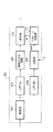
図1には、本発明に係る超音波診断装置の好適な実施形態が示されている。この超音波診断装置は血栓映像化機能を有しており、すなわち血栓に相関がある瞬時ピークを映像化するモードを有している。
【0023】
プローブ10は超音波の送受波を行う超音波探触子であり、プローブ10は生体8の表面上に当接される。もちろん、このプローブ10は体腔内に挿入されるプローブであってもよい。プローブ10は複数の振動素子からなるアレイ振動子を有しており、そのアレイ振動子に対して電子走査を実行することによって超音波ビームが電子的にスキャンされる。図1には、その超音波ビームが符号12で示されており、その超音波ビーム12を電子的にスキャンすることによって走査面14が形成される。ちなみに、その電子走査方式としては例えば電子セクタ走査や電子リニア走査などが知られている。
【0024】
なお、本実施形態においては二次元の走査面14がデータ取込領域として形成されているが、本発明は三次元データ取込領域が形成される場合にも適用可能である。
【0025】
送信部20はプローブ10に対して送信信号を供給する回路である。受信部22はプローブ10から出力される受信信号に対して整相加算処理などを実行する回路である。送信部20の作用によって送信ビームが電子的に形成され、受信部22の作用によって受信ビームが電子的に形成される。この受信部22はいわゆるデジタルビームフォーマーを有するものであるのが望ましい。
【0026】
断層画像形成部24は受信信号に基づいて断層画像すなわちBモード画像を形成する回路である。この断層画像形成部24によって形成された断層画像100は合成部32に出力されている。
【0027】
ドプラ画像形成部26は、受信信号に基づいて二次元ドプラ画像(カラードプラ画像)を形成する回路である。そのドプラ画像101は合成部32に出力されている。
【0028】
瞬時ピーク画像形成部28は、上述した瞬時ピークすなわちHITSを検出し、その瞬時ピークを表す二次元の画像を瞬時ピーク画像102として形成する回路である。
【0029】
残像処理部30は、瞬時ピーク画像102に対してフレーム間相関処理を実行し、これによって瞬時ピークの残像処理を実行する回路である。その残像処理部30から残像処理が施された瞬時ピーク画像103が合成部32に出力される。
【0030】
合成部32は、断層画像100及びドプラ画像101のうちの一方又は両方に対して瞬時ピーク画像103を合成する機能を有する。この場合、少なくともその合成画像104上において、他の画像から瞬時ピークが際だつように、当該瞬時ピークに対するハイライト表示や色付けを行うのが望ましい。その合成画像104は表示部34に出力され、その表示部34において合成画像が表示される。もちろん、その表示部34に各画像101,100,103のいずれかを単独で表示するようにしてもよい。
【0031】
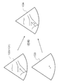
図2には、合成部32の作用が概念的に示されている。断層画像100及びドプラ画像101は走査面14に対応した画像であり、また瞬時ピーク画像103も走査面14に対応した画像である。合成部32によって、それらの画像が合成され合成画像104が形成される。その合成画像104においては、背景となる生体組織の断面上において瞬時ピークが明瞭に表示される。したがって、このような画像によれば、瞬時ピークの発生場所やこの挙動を容易に把握可能である。特に、本実施形態においては残像処理部30によって瞬時ピークに対する残像処理が施されているため、瞬時ピークの移動軌跡を観測することも可能である。上記のように、瞬時ピークの発生確率は一般に非常に低く、このため従来において単にドプラパワースペクトル上において、瞬時ピークを目視観察すると、当該瞬時ピークを見落とす可能性が高かった。しかしながら、本実施形態によれば、合成画像104上において瞬時ピークを容易にかつ確実に特定できるという利点がある。
【0032】
したがって、本実施形態に係る装置によれば、血栓に相関がある瞬時ピークを確実に特定して、例えば脳梗塞などの危険度合いを精度良く診断することが可能となる。また、血栓が生体内のいずれの箇所において発生し、あるいは移動しているかを明確に認識可能であり、例えば血管の狭窄部位における血栓の詰まりや停留といった診断を行うことも可能となる。
【0033】
次に、図1に示した各構成の具体的な内容について説明する。
【0034】
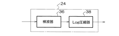
図3には図1に示した断層画像形成部24の具体的な構成例が示されている。断層画像形成部24は検波器36及びLog圧縮器38で構成される。検波器36は受信信号に対して検波を行い、エンベロープ信号を出力する回路である。Log圧縮器38はそのエンベロープ信号に対する対数圧縮処理を実行する回路である。すなわち信号強度の低い成分の強度をより増大し、一方において信号強度の高い成分を相対的に抑圧する処理を行う回路である。ちなみに、対数圧縮を行った後に信号の検波を行うようにしてもよい。図3に示される回路構成自体は公知の構成である。
【0035】
図4には、ドプラ画像形成部26の具体的な構成例が示されている。
【0036】
受信信号は直交検波器40に入力され、受信信号に対して互いに90度位相が異なる参照信号が混合され、これによって受信信号が複素信号に変換される。ちなみに、その複素信号は所定のローパスフィルタを通過し、これによりベースバンド領域の成分のみが複素信号として出力される。
【0037】
ウォールモーションフィルタ42は、例えば心臓壁などの低速運動体からの巨大なエコー成分を除去するために複素信号中の高域成分のみを通過させるフィルタである。
【0038】
自己相関器44は、周知のように、直交検波後の複素信号に対して自己相関演算を行うものである。その自己相関結果は、平均化回路46において平均化処理された後、速度演算器48に入力される。速度演算器48は自己相関後の結果から位相を検出することによって速度を演算する回路である。この図4に示す回路構成自体は公知の構成である。
【0039】
図5及び図6には瞬時ピーク画像形成部28の具体的な構成例が示されている。
【0040】
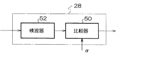
図5に示す例では、受信信号がまず比較器50に入力され、受信信号と閾値αとが比較される。この閾値αは瞬時ピークを弁別するための所定のレベルに設定されるものである。したがって、この比較器50の出力として瞬時ピーク(あるいはその可能性がある信号)が出力されることになり、検波器52はその比較器50から出力された信号に対する検波を実行する。その結果、通常のBモード画像と同様の領域をもった瞬時ピーク画像が構成されることになる。なお、図5に示す例では比較器50の後段に検波器52が設けられていたが、それらの配置を逆にしてもよい。その場合の構成例が図6に示されている。
【0041】
図5及び図6に示す例では、受信信号のレベルすなわち強度に基づいて瞬時ピークの判別を行っていた。しかしながら、受信信号に含まれるドプラ成分の強度(パワー)に基づいて瞬時ピークの判別を行うようにしてもよい。
【0042】
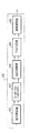
図7には、図1に示した残像処理部30の構成例が示されている。瞬時ピーク画像形成部28から出力される信号は加算器58を介してフレームメモリ54に入力され、そこで1フレーム分の情報が格納される。フレームメモリ54から出力される信号は重み付け回路56に入力され、その信号に対して重み付け値βが乗算される。このβは1よりも低い値に設定される。そのように重み付けがされた信号が加算器58において瞬時ピーク画像形成部28から出力される信号に加算される。そして、その加算された信号がフレームメモリ54に格納され、上記の工程が繰り返し実行される。その結果、フレームメモリ54には最新のフレーム及びそれ以前の複数のフレームの情報が混合して格納されることになり、すなわち、瞬時ピークについての残像処理を行うことができる。図7に示す回路構成以外にも残像処理を行うための他の回路構成を採用し得る。
【0043】
図8、図10及び図11には、図1に示した瞬時ピーク画像形成部28の他の構成例が示されている。
【0044】
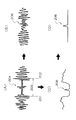
図8に示す構成の作用を説明するために、まず図9を参照すると、その図9(A)には受信信号の一例が示されている。ここで、符号201及び202は血管壁に相当する部分を示しており、符号203が血管壁の間の血流部分を示している。また、符号204はその血流部分内に存在する血栓すなわち即ち瞬時ピークを表している。
【0045】
ところで、通常の断層画像の形成処理にあたっては、図3に示したように受信信号に対する対数圧縮処理が実行される。そのような対数圧縮処理を経た信号が図9(B)に示されている。図示されるように瞬時ピーク206は他の信号成分の中に埋没しており、その瞬時ピーク206を判別するのは困難となっている。
【0046】
そこで、対数圧縮処理が行われる前に瞬時ピークを判定する。図9の(C)には(A)に示す信号に対する検波を行った後の信号が示されている。ここで、符号208は瞬時ピークを示している。(B)と(C)との対比から明らかなように、対数圧縮前の受信信号によれば、瞬時ピークの判別精度を高められる。但し、瞬時ピークの他に血管壁に相当する比較的強大な信号成分が発生しており、瞬時ピークのみを判別する工夫が必要となる。そこで、本実施形態においては弱い信号に囲まれた強い信号をパターン認識することによって、瞬時ピーク208を特定している。
【0047】
すなわち、(C)に示すように、時間軸上において弱い信号の中に強い信号が存在している場合には、(D)に示すようにそれを瞬時ピーク208として特定するものである。
【0048】
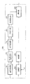
図8に示す回路構成は、図9に示した作用を実現するためのものである。検波器60において受信信号に対する検波が実行され、その検波後の受信信号は2つのローパスフィルタ(LPF)62,64に入力される。ここで、ローパスフィルタ62は受信信号からノイズを除去するための回路であり、そのフィルタリング後の受信信号が移動平均化回路66に入力され、当該受信信号に対する移動平均処理が実行される。その処理後の信号が選択器70に入力される。
【0049】
一方、ローパスフィルタ64は血管の内外を識別可能な程度までに受信信号に対して平滑化を行うものである。その平滑化後の受信信号は比較器68に入力され、受信信号に対して閾値αが比較される。そして、閾値αを超える信号成分がパターン判別器72に入力される。パターン判別器72は、上述したように、弱い信号中に強い信号がある場合にそれを瞬時ピークと判定する回路である。瞬時ピークが判別された場合、その瞬時ピークのタイミングに同期したゲートパルスが選択器70に出力される。選択器70はそのゲートパルスのパルス期間内だけ入力信号を通過させる。その結果、選択器70から血管内に存在する瞬時ピークに相当する信号成分のみが出力されることになる。よって図8に示す回路構成によって瞬時ピーク画像を形成すれば、血栓からのものを効果的に選択でき、血栓以外のものを効果的に排除できると利点がある。
【0050】
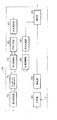
図10に示す構成例において、受信信号は直交検波器74に入力され、上述したように直交検波によって受信信号が複素信号に変換される。その複素信号がウォールモーションフィルタ76を通過した後、自己相関器78に入力され、複素信号に対する自己相関が実行される。その自己相関結果は、平均化回路80を介して速度演算器82に出力され、その速度演算器82において自己相関結果から速度が演算される。ちなみに、以上の各構成は図4に示したドプラ画像形成部26と同様であり、したがってドプラ画像形成部26と構成74〜82とを兼用させることも可能である。
【0051】
一方、受信信号は比較器84に入力されており、受信信号が閾値αと比較される。そして閾値αを超える信号成分が検波器86に入力され、これは図5に示した処理と同様である。選択器88は、検波器86から出力される信号成分の内で所定の速度範囲内の速度をもった信号成分のみを選択する回路である。すなわち、全ての瞬時ピークを画像化するのではなく、血栓の移動速度を考慮し、所定の速度条件を満たす瞬時ピークのみを特定するものである。この図10に示す構成例によればより血栓の特定精度を高められるという利点がある。
【0052】
図11にも瞬時ピーク画像形成部28の構成例が示されており、図10に示した同様の構成には同一符号を付しその説明を省略する。この構成例では、ウォールモーションフィルタ76の出力が振幅演算器89に入力されている。振幅演算器89は複素信号を構成する実数部及び虚数部のそれぞれの二乗を互いに加算し、その加算結果に対して平方根を演算することによって、振幅(パワー)を演算する回路である。その演算結果は平均化回路90を介して選択器92に出力されている。この選択器92は、検波器86から出力される信号成分の内で、所定の速度範囲内に速度が属するという条件を満たし、かつ所定のパワー範囲内(あるいは所定のパワー以上)にパワーが属するという条件を満たす信号成分のみを通過させる回路である。この図11に示す回路構成によれば、血栓に相当する瞬時ピークの判別精度をより高められる。
【0053】
ちなみに、上記の各構成例においては、受信信号と閾値αとが比較され、それによって瞬時ピークの判別が行われていたが、もちろん、上述したように受信信号に含まれるドプラ成分のパワーと閾値とを比較することによって瞬時ピークを判別するようにしてもよい。その場合においては、図11に示す回路構成において、平均化回路90から出力される信号に対して閾値との比較演算を行えばよい。その場合には選択器92において比較演算も行うことにすれば、比較器84及び検波器86は不要となる。
【0054】
なお、上記の実施形態においては二次元画像としての超音波画像に対して二次元画像としての瞬時ピーク画像が合成されていたが、三次元画像としての超音波画像に対して三次元画像としての瞬時ピーク画像を合成するようにしてもよい。このような構成によれば、例えば心臓を立体的に表現し、その心臓の中を流れる血栓を三次元的に映像化できるという利点がある。
【0055】
【発明の効果】
以上説明したように、本発明によれば、瞬時ピークの発生や移動を空間的に認識できる画像を提供できる。
【図面の簡単な説明】
【図1】 本発明に係る超音波診断装置の全体構成を示すブロック図である。
【図2】 超音波画像と瞬時ピーク画像の合成を説明するための図である。
【図3】 図1に示す断層画像形成部の構成例を示す図である。
【図4】 図1に示すドプラ画像形成部の構成例を示す図である。
【図5】 図1に示す瞬時ピーク画像形成部の構成例を示す図である。
【図6】 図1に示す瞬時ピーク画像形成部の他の構成例を示す図である。
【図7】 図1に示す残像処理部の構成例を示す図である。
【図8】 図1に示す瞬時ピーク画像形成部の他の構成例を示す図である。
【図9】 図8に示す構成の作用を説明するための図である。
【図10】 図1に示す瞬時ピーク画像形成部の他の構成例を示す図である。
【図11】 図1に示す瞬時ピーク画像形成部の他の構成例を示す図である。
【符号の説明】
8 生体、10 プローブ、12 超音波ビーム、14 走査面(データ取込領域)、24 断層画像形成部、26 ドプラ画像形成部、28 瞬時ピーク画像形成部、30 残像処理部、32 合成部、34 表示部。[0001]
BACKGROUND OF THE INVENTION
The present invention relates to an ultrasonic diagnostic apparatus, and more particularly to an apparatus capable of imaging information related to a thrombus.
[0002]
[Prior art]
When a power spectrum is displayed based on an echo signal from a blood flow flowing through a blood vessel in the brain, a high-luminance portion (instantaneous peak) may be observed occasionally. Here, the power spectrum is a graph with the horizontal axis representing the time axis and the vertical axis representing the velocity axis, and the luminance corresponds to the power of the Doppler component. The portion of high brightness observed in such a power spectrum is generally called HITS (High Intensity Transient Signal). Clinically, it is known that a person with a higher frequency of HITS is more likely to have a cerebral infarction. However, the generation mechanism has many unknown parts. In any case, the occurrence frequency of HITS is estimated to be an index of the risk of potential thrombus occurrence in each person.
[0003]
Conventionally, when observing the frequency of HITS, an ultrasonic probe for intracerebral diagnosis is brought into contact with the vicinity of the temple of the head, and ultrasonic pulses are transmitted and received by the ultrasonic probe. A Doppler component (Doppler signal) corresponding to blood flow motion information is extracted from the received signal thus obtained, and a power spectrum is calculated by calculating the power of the Doppler component. The power spectrum displayed on the screen is visually observed for a certain time (for example, 30 minutes), and the number of occurrences of the HITS is manually counted.
[0004]
[Problems to be solved by the invention]
However, according to the long-time visual observation as described above, the burden on the observer is very large. In addition, there is a problem in diagnosis because it is difficult to obtain objective data because each person's judgment standard varies depending on how high the brightness is regarded as HITS.
[0005]
In particular, in the past, since HITS was monitored on the power spectrum, it was impossible to recognize in which part of the living body it occurred and how it moved.
[0006]
The present invention has been made in view of the above-described conventional problems, and an object of the present invention is to make it possible to spatially recognize the occurrence and movement of HITS, which is said to have a correlation with thrombus.
[0007]
Another object of the present invention is to form a new image representing the possible presence of a thrombus.
[0008]
[Means for Solving the Problems]
(1) In order to achieve the above-mentioned object, the present invention scans an ultrasonic beam to form a two-dimensional or three-dimensional data capturing area, and the intensity of a received signal from the transducer. Instantaneous peak determination means for determining a predetermined instantaneous peak based on information, and forming a two-dimensional or three-dimensional instantaneous peak image corresponding to the two-dimensional or three-dimensional data capture area based on the instantaneous peak And an instantaneous peak image forming means.
[0009]
According to the above configuration, an instantaneous peak (HITS) that seems to have a correlation with a thrombus can be determined in the data capture region, and a two-dimensional image or a three-dimensional image including the instantaneous peak can be formed. Therefore, on the image, it is possible to grasp the moving direction of the instantaneous peak, the speed or distribution of the movement, and the like.
[0010]
Preferably, power receiving means for calculating power based on the received signal is included, and the intensity information of the received signal is the power of the received signal. Preferably, the power calculation means calculates the power of the Doppler component in the received signal. Preferably, the received signal strength information is an amplitude value of the received signal.
[0011]
Preferably, it includes speed calculating means for calculating a speed from the received signal, and the instantaneous peak determining means determines the instantaneous peak based on the intensity information and the speed. According to this configuration, since the instantaneous peak can be determined not only by intensity information but also by speed information, the determination accuracy can be improved.
[0012]
Preferably, on the basis of the received signal, an ultrasonic image forming unit that forms a two-dimensional or three-dimensional ultrasonic image corresponding to the two-dimensional or three-dimensional data capture area, the instantaneous peak image, and the supersonic peak image Image synthesizing means for synthesizing the sound wave image and forming a synthesized image.
[0013]
According to the above configuration, the presence of an instantaneous peak can be visualized on a conventional two-dimensional image or three-dimensional image, and the movement and behavior of the instantaneous peak can be grasped in correlation with other organs and blood vessel running states.
[0014]
Preferably, the image processing apparatus includes afterimage processing means for performing afterimage processing of an instantaneous peak between frames on the instantaneous peak image. According to this configuration, when the instantaneous peak disappears in a short time or when the moving speed of the instantaneous peak is large and the frame is out of the frame in a short time, the presence or locus can be clearly expressed.
[0015]
(2) In order to achieve the above object, the present invention includes a transmission / reception unit for transmitting / receiving ultrasonic waves, and a logarithmic compressor for performing logarithmic compression on a received signal from the transmission / reception unit. First image forming means for forming an ultrasonic image that has undergone processing, and second image processing for forming an instantaneous peak image based on a branch received signal extracted from a path between the transmission / reception means and the logarithmic compression means Means, and image synthesis means for synthesizing the ultrasonic image and the instantaneous peak image.
[0016]
In a normal ultrasonic diagnostic apparatus, logarithmic compression is performed on a received signal because of the relationship with the dynamic range of the signal. However, such logarithmic compression may reduce the accuracy of instantaneous peak discrimination. . Therefore, the instantaneous peak is determined for a received signal that has not been subjected to such logarithmic compression.
[0017]
Preferably, the second image processing means includes instantaneous peak discrimination means for discriminating a strong reflector present in the blood vessel as the instantaneous peak based on the waveform of the branch reception signal.
[0018]
Preferably, the instantaneous peak discriminating unit determines that a peak exceeding a predetermined threshold is present in the region where the level of the branch reception signal falls below a predetermined threshold as the instantaneous peak.
[0019]
Echoes from the bloodstream are inherently weaker than echoes from other real tissues (such as blood vessel walls), while the intensity of instantaneous echoes is high. Therefore, using such characteristics, the discrimination accuracy of the instantaneous peak is improved.
[0020]
(3) In order to achieve the above object, the thrombus imaging device according to the present invention scans an ultrasonic beam and forms a scanning surface, and based on a reception signal from the transmission / reception unit, An instantaneous peak image forming means for determining an instantaneous peak correlated with a thrombus and forming an instantaneous peak image representing the instantaneous peak on the scanning plane; and a display means for displaying the instantaneous peak image. Features.
[0021]
DETAILED DESCRIPTION OF THE INVENTION
Hereinafter, preferred embodiments of the present invention will be described with reference to the drawings.
[0022]
FIG. 1 shows a preferred embodiment of an ultrasonic diagnostic apparatus according to the present invention. This ultrasonic diagnostic apparatus has a thrombus imaging function, that is, a mode for imaging an instantaneous peak correlated with a thrombus.
[0023]
The
[0024]
In the present embodiment, the two-dimensional scanning plane 14 is formed as a data capture area, but the present invention can also be applied to the case where a three-dimensional data capture area is formed.
[0025]
The
[0026]
The tomographic
[0027]
The Doppler
[0028]
The instantaneous peak
[0029]
The
[0030]
The combining
[0031]
FIG. 2 conceptually shows the operation of the combining
[0032]
Therefore, according to the apparatus according to the present embodiment, it is possible to accurately identify an instantaneous peak correlated with a thrombus and accurately diagnose the degree of danger such as cerebral infarction. In addition, it is possible to clearly recognize in which part of the living body a thrombus is generated or moving, and for example, it is possible to make a diagnosis such as clogging or retention of a thrombus in a stenotic region of a blood vessel.
[0033]
Next, specific contents of each configuration shown in FIG. 1 will be described.
[0034]
FIG. 3 shows a specific configuration example of the tomographic
[0035]
FIG. 4 shows a specific configuration example of the Doppler
[0036]
The received signal is input to the
[0037]
The
[0038]
As is well known, the
[0039]
5 and 6 show specific configuration examples of the instantaneous peak
[0040]
In the example shown in FIG. 5, the received signal is first input to the
[0041]
In the example shown in FIGS. 5 and 6, the instantaneous peak is determined based on the level, that is, the intensity of the received signal. However, the instantaneous peak may be determined based on the strength (power) of the Doppler component included in the received signal.
[0042]
FIG. 7 shows a configuration example of the
[0043]
8, 10, and 11 illustrate other configuration examples of the instantaneous peak
[0044]
In order to explain the operation of the configuration shown in FIG. 8, first, referring to FIG. 9, FIG. 9A shows an example of a received signal. Here,
[0045]
By the way, in a normal tomographic image forming process, a logarithmic compression process is performed on a received signal as shown in FIG. A signal that has undergone such logarithmic compression processing is shown in FIG. As shown in the drawing, the
[0046]
Therefore, an instantaneous peak is determined before logarithmic compression processing is performed. FIG. 9C shows a signal after detection for the signal shown in FIG. Here,
[0047]
That is, as shown in (C), when a strong signal exists among weak signals on the time axis, it is specified as an
[0048]
The circuit configuration shown in FIG. 8 is for realizing the operation shown in FIG. Detection is performed on the received signal in the
[0049]
On the other hand, the low-pass filter 64 smoothes the received signal to the extent that the inside and outside of the blood vessel can be identified. The smoothed received signal is input to the
[0050]
In the configuration example shown in FIG. 10, the received signal is input to the
[0051]
On the other hand, the received signal is input to the
[0052]
FIG. 11 also shows a configuration example of the instantaneous peak
[0053]
Incidentally, in each of the above configuration examples, the received signal and the threshold value α are compared, and the instantaneous peak is discriminated. Of course, as described above, the power and threshold value of the Doppler component included in the received signal are as described above. The instantaneous peak may be discriminated by comparing. In that case, in the circuit configuration shown in FIG. 11, the signal output from the averaging
[0054]
In the above embodiment, an instantaneous peak image as a two-dimensional image is synthesized with an ultrasonic image as a two-dimensional image. However, an ultrasonic image as a three-dimensional image is synthesized as a three-dimensional image. You may make it synthesize | combine an instantaneous peak image. According to such a configuration, there is an advantage that, for example, the heart is represented in three dimensions, and a thrombus flowing in the heart can be visualized in three dimensions.
[0055]
【The invention's effect】
As described above, according to the present invention, an image capable of spatially recognizing the occurrence and movement of an instantaneous peak can be provided.
[Brief description of the drawings]
FIG. 1 is a block diagram showing the overall configuration of an ultrasonic diagnostic apparatus according to the present invention.
FIG. 2 is a diagram for explaining synthesis of an ultrasonic image and an instantaneous peak image.
FIG. 3 is a diagram illustrating a configuration example of a tomographic image forming unit illustrated in FIG. 1;
4 is a diagram illustrating a configuration example of a Doppler image forming unit illustrated in FIG. 1; FIG.
FIG. 5 is a diagram illustrating a configuration example of an instantaneous peak image forming unit illustrated in FIG. 1;
6 is a diagram illustrating another configuration example of the instantaneous peak image forming unit illustrated in FIG. 1. FIG.
7 is a diagram illustrating a configuration example of an afterimage processing unit illustrated in FIG. 1. FIG.
FIG. 8 is a diagram showing another configuration example of the instantaneous peak image forming unit shown in FIG. 1;
9 is a diagram for explaining the operation of the configuration shown in FIG. 8. FIG.
10 is a diagram showing another configuration example of the instantaneous peak image forming unit shown in FIG.
FIG. 11 is a diagram illustrating another configuration example of the instantaneous peak image forming unit illustrated in FIG. 1;
[Explanation of symbols]
8 biological body, 10 probe, 12 ultrasonic beam, 14 scanning plane (data acquisition area), 24 tomographic image forming unit, 26 Doppler image forming unit, 28 instantaneous peak image forming unit, 30 afterimage processing unit, 32 combining unit, 34 Display section.
Claims (11)
前記送受波器からの受信信号の強度情報に基づいて、血栓に相関性がある瞬時ピークを判定する瞬時ピーク判定手段と、
前記瞬時ピークに基づいて、前記二次元又は三次元のデータ取込領域に対応した二次元又は三次元の瞬時ピーク画像を形成する瞬時ピーク画像形成手段と、
を含むことを特徴とする超音波診断装置。A transducer that scans an ultrasonic beam to form a two-dimensional or three-dimensional data acquisition area;
Based on the intensity information of the received signal from the transducer, an instantaneous peak determination means for determining an instantaneous peak correlated with a thrombus ,
Based on the instantaneous peak, instantaneous peak image forming means for forming a two-dimensional or three-dimensional instantaneous peak image corresponding to the two-dimensional or three-dimensional data capture area;
An ultrasonic diagnostic apparatus comprising:
前記受信信号に基づいてパワーを演算するパワー演算手段を含み、
前記受信信号の強度情報は前記受信信号のパワーであることを特徴とする超音波診断装置。The apparatus of claim 1.
Power calculating means for calculating power based on the received signal,
The ultrasonic diagnostic apparatus, wherein the intensity information of the received signal is the power of the received signal.
前記パワー演算手段は前記受信信号中のドプラ成分のパワーを演算することを特徴とする超音波診断装置。The apparatus of claim 2.
The ultrasonic diagnostic apparatus, wherein the power calculation means calculates the power of a Doppler component in the received signal.
前記受信信号の強度情報は前記受信信号の振幅値であることを特徴とする超音波診断装置。The apparatus of claim 1.
The ultrasonic diagnostic apparatus, wherein the received signal intensity information is an amplitude value of the received signal.
前記受信信号から速度を演算する速度演算手段を含み、
前記瞬時ピーク判定手段は、前記強度情報及び前記速度に基づいて前記瞬時ピークを判定することを特徴とする超音波診断装置。The apparatus of claim 1.
Speed calculation means for calculating the speed from the received signal,
The ultrasonic diagnostic apparatus, wherein the instantaneous peak determination means determines the instantaneous peak based on the intensity information and the speed.
前記受信信号に基づいて、前記二次元又は三次元のデータ取込領域に対応した二次元又は三次元の超音波画像を形成する超音波画像形成手段と、
前記瞬時ピーク画像と前記超音波画像とを合成し、合成画像を形成する画像合成手段と、
を含むことを特徴とする超音波診断装置。The apparatus of claim 1.
Ultrasonic image forming means for forming a two-dimensional or three-dimensional ultrasonic image corresponding to the two-dimensional or three-dimensional data capture area based on the received signal;
Image synthesizing means for synthesizing the instantaneous peak image and the ultrasonic image and forming a synthesized image;
An ultrasonic diagnostic apparatus comprising:
前記瞬時ピーク画像に対し、フレーム間にわたって残像処理を施す残像処理手段を含むことを特徴とする超音波診断装置。The apparatus of claim 1.
An ultrasonic diagnostic apparatus comprising afterimage processing means for performing afterimage processing between frames on the instantaneous peak image.
前記送受波手段からの受信信号に対して対数圧縮を行う対数圧縮器を含み、対数圧縮処理を経た超音波画像を形成する第1画像形成手段と、
前記送受波手段と前記対数圧縮手段との間の経路から取り出された分岐受信信号に基づいて、血栓に相関性がある瞬時ピークを含む瞬時ピーク画像を形成する第2画像処理手段と、
前記超音波画像と前記瞬時ピーク画像とを合成する画像合成手段と、
を含むことを特徴とする超音波診断装置。Transmission / reception means for transmitting / receiving ultrasonic waves;
A first image forming unit that includes a logarithmic compressor that performs logarithmic compression on a received signal from the wave transmitting / receiving unit, and that forms an ultrasonic image that has undergone logarithmic compression processing;
A second image processing means for forming an instantaneous peak image including an instantaneous peak correlated with a thrombus, based on a branched received signal taken from a path between the transmission / reception means and the logarithmic compression means;
Image synthesizing means for synthesizing the ultrasonic image and the instantaneous peak image;
An ultrasonic diagnostic apparatus comprising:
前記第2画像処理手段は、前記分岐受信信号の波形に基づいて、血管中に存在する強反射体を前記瞬時ピークとして判別する瞬時ピーク判別手段を含むことを特徴とする超音波診断装置。The apparatus of claim 8.
The ultrasonic diagnostic apparatus characterized in that the second image processing means includes instantaneous peak discrimination means for discriminating a strong reflector present in a blood vessel as the instantaneous peak based on the waveform of the branch reception signal.
前記瞬時ピーク判別手段は、前記分岐受信信号のレベルが所定閾値以下に落ち込んだ領域中に所定閾値を越えるピークがある場合にそれを前記瞬時ピークとして判定することを特徴とする超音波診断装置。The apparatus of claim 9.
The ultrasonic diagnostic apparatus according to claim 1, wherein the instantaneous peak determination unit determines a peak exceeding a predetermined threshold in an area where the level of the branch reception signal falls below a predetermined threshold as the instantaneous peak.
前記送受波手段からの受信信号に基づいて、血栓に相関性がある瞬時ピークを判定し、前記走査面上に瞬時ピークを表した瞬時ピーク画像を形成する瞬時ピーク画像形成手段と、
前記瞬時ピーク画像を表示する表示手段と、
を含むことを特徴とする血栓映像化装置。Wave transmitting / receiving means for scanning an ultrasonic beam to form a scanning surface;
Instantaneous peak image forming means for determining an instantaneous peak correlated with a thrombus based on a received signal from the wave transmitting / receiving means and forming an instantaneous peak image representing the instantaneous peak on the scanning plane;
Display means for displaying the instantaneous peak image;
A thrombus imaging device comprising:
Priority Applications (1)
| Application Number | Priority Date | Filing Date | Title |
|---|---|---|---|
| JP32465499A JP4398024B2 (en) | 1999-11-15 | 1999-11-15 | Ultrasonic diagnostic device and thrombus imaging device |
Applications Claiming Priority (1)
| Application Number | Priority Date | Filing Date | Title |
|---|---|---|---|
| JP32465499A JP4398024B2 (en) | 1999-11-15 | 1999-11-15 | Ultrasonic diagnostic device and thrombus imaging device |
Publications (2)
| Publication Number | Publication Date |
|---|---|
| JP2001137242A JP2001137242A (en) | 2001-05-22 |
| JP4398024B2 true JP4398024B2 (en) | 2010-01-13 |
Family
ID=18168251
Family Applications (1)
| Application Number | Title | Priority Date | Filing Date |
|---|---|---|---|
| JP32465499A Expired - Fee Related JP4398024B2 (en) | 1999-11-15 | 1999-11-15 | Ultrasonic diagnostic device and thrombus imaging device |
Country Status (1)
| Country | Link |
|---|---|
| JP (1) | JP4398024B2 (en) |
Families Citing this family (4)
| Publication number | Priority date | Publication date | Assignee | Title |
|---|---|---|---|---|
| EP1627602B1 (en) * | 2003-05-29 | 2012-04-25 | Olympus Corporation | Ultrasonographic device and ultrasonographic device data processing method |
| RU2423921C1 (en) * | 2010-02-10 | 2011-07-20 | Государственное образовательное учреждение дополнительного профессионального образования "Казанская государственная медицинская академия Федерального агентства по здравоохранению и социальному развитию" | Method of diagnosing thrombosis of deep veins |
| JP5984252B2 (en) * | 2012-04-13 | 2016-09-06 | 東芝メディカルシステムズ株式会社 | Ultrasonic diagnostic apparatus, image processing apparatus, and program |
| RU2547072C2 (en) * | 2013-01-18 | 2015-04-10 | Федеральное государственное бюджетное учреждение "Федеральный центр травматологии, ортопедии и эндопротезирования" Министерства здравоохранения РФ (г. Чебоксары) | Ultrasonic diagnostic technique for initial stages of deep tibial venous thrombosis in early postoperative period |
-
1999
- 1999-11-15 JP JP32465499A patent/JP4398024B2/en not_active Expired - Fee Related
Also Published As
| Publication number | Publication date |
|---|---|
| JP2001137242A (en) | 2001-05-22 |
Similar Documents
| Publication | Publication Date | Title |
|---|---|---|
| JP5150267B2 (en) | Ultrasound diagnostic imaging system to detect liver damage | |
| JP4722283B2 (en) | Method and apparatus for motion visualization in ultrasonic flow imaging using continuous data acquisition | |
| JP3423356B2 (en) | Ultrasound diagnostic equipment | |
| US5533510A (en) | Real time ultrasound endocardial displacement display | |
| EP1579244B1 (en) | Segmentation tool for identifying flow regions in an imaging system | |
| JP4829960B2 (en) | Ultrasonic diagnostic equipment | |
| JP5627890B2 (en) | Dual path processing for optimal speckle tracking | |
| JP4627366B2 (en) | Method and apparatus for motion visualization in ultrasonic flow imaging using packet data acquisition | |
| US6620103B1 (en) | Ultrasonic diagnostic imaging system for low flow rate contrast agents | |
| US20110208061A1 (en) | Ultrasonic lesion identification using temporal parametric contrast images | |
| US8864671B2 (en) | Methods and systems for color flow imaging | |
| US20090067699A1 (en) | Optimization of velocity scale for color tissue doppler imaging | |
| JP3397748B2 (en) | Color image display method and apparatus in color Doppler image system | |
| JP2004520875A (en) | Doppler ultrasound method for detecting emboli | |
| JP2004522515A (en) | Adaptive image processing for spatial compounding | |
| JPH105225A (en) | Three-dimensional ultrasonic scanning of tissue movement and apparatus therefor | |
| CN101375803B (en) | Ultrasonic diagnosis device | |
| JP3029315B2 (en) | Ultrasound blood flow imaging device | |
| JP2003061958A (en) | Ultrasound diagnostic equipment | |
| JP4398024B2 (en) | Ultrasonic diagnostic device and thrombus imaging device | |
| JP2002224114A (en) | Ultrasonic diagnostic apparatus and ultrasonic diagnostic method | |
| KR101014558B1 (en) | Elastic Image Forming Method Using Strain Normalization and Ultrasonic System Therefor | |
| US20060030777A1 (en) | T-statistic method for suppressing artifacts in blood vessel ultrasonic imaging | |
| WO2007119609A1 (en) | Embolus observing method and device, and ultrasonograph using them | |
| JP4219626B2 (en) | Ultrasonic tomographic image generator |
Legal Events
| Date | Code | Title | Description |
|---|---|---|---|
| A621 | Written request for application examination |
Free format text: JAPANESE INTERMEDIATE CODE: A621 Effective date: 20060822 |
|
| RD04 | Notification of resignation of power of attorney |
Free format text: JAPANESE INTERMEDIATE CODE: A7424 Effective date: 20060822 |
|
| A977 | Report on retrieval |
Free format text: JAPANESE INTERMEDIATE CODE: A971007 Effective date: 20090205 |
|
| A131 | Notification of reasons for refusal |
Free format text: JAPANESE INTERMEDIATE CODE: A131 Effective date: 20090728 |
|
| A521 | Written amendment |
Free format text: JAPANESE INTERMEDIATE CODE: A523 Effective date: 20090911 |
|
| TRDD | Decision of grant or rejection written | ||
| A01 | Written decision to grant a patent or to grant a registration (utility model) |
Free format text: JAPANESE INTERMEDIATE CODE: A01 Effective date: 20091020 |
|
| A01 | Written decision to grant a patent or to grant a registration (utility model) |
Free format text: JAPANESE INTERMEDIATE CODE: A01 |
|
| A61 | First payment of annual fees (during grant procedure) |
Free format text: JAPANESE INTERMEDIATE CODE: A61 Effective date: 20091022 |
|
| FPAY | Renewal fee payment (prs date is renewal date of database) |
Free format text: PAYMENT UNTIL: 20121030 Year of fee payment: 3 |
|
| R150 | Certificate of patent (=grant) or registration of utility model |
Free format text: JAPANESE INTERMEDIATE CODE: R150 |
|
| FPAY | Renewal fee payment (prs date is renewal date of database) |
Free format text: PAYMENT UNTIL: 20131030 Year of fee payment: 4 |
|
| R250 | Receipt of annual fees |
Free format text: JAPANESE INTERMEDIATE CODE: R250 |
|
| LAPS | Cancellation because of no payment of annual fees |