JP4432809B2 - 回転角度検出装置 - Google Patents
回転角度検出装置 Download PDFInfo
- Publication number
- JP4432809B2 JP4432809B2 JP2005076812A JP2005076812A JP4432809B2 JP 4432809 B2 JP4432809 B2 JP 4432809B2 JP 2005076812 A JP2005076812 A JP 2005076812A JP 2005076812 A JP2005076812 A JP 2005076812A JP 4432809 B2 JP4432809 B2 JP 4432809B2
- Authority
- JP
- Japan
- Prior art keywords
- detection
- rotation angle
- rotating body
- spur gear
- rotation
- Prior art date
- Legal status (The legal status is an assumption and is not a legal conclusion. Google has not performed a legal analysis and makes no representation as to the accuracy of the status listed.)
- Expired - Fee Related
Links
Images


Classifications
-
- B—PERFORMING OPERATIONS; TRANSPORTING
- B62—LAND VEHICLES FOR TRAVELLING OTHERWISE THAN ON RAILS
- B62D—MOTOR VEHICLES; TRAILERS
- B62D15/00—Steering not otherwise provided for
- B62D15/02—Steering position indicators ; Steering position determination; Steering aids
- B62D15/021—Determination of steering angle
- B62D15/0215—Determination of steering angle by measuring on the steering column
-
- G—PHYSICS
- G01—MEASURING; TESTING
- G01D—MEASURING NOT SPECIALLY ADAPTED FOR A SPECIFIC VARIABLE; ARRANGEMENTS FOR MEASURING TWO OR MORE VARIABLES NOT COVERED IN A SINGLE OTHER SUBCLASS; TARIFF METERING APPARATUS; MEASURING OR TESTING NOT OTHERWISE PROVIDED FOR
- G01D5/00—Mechanical means for transferring the output of a sensing member; Means for converting the output of a sensing member to another variable where the form or nature of the sensing member does not constrain the means for converting; Transducers not specially adapted for a specific variable
- G01D5/12—Mechanical means for transferring the output of a sensing member; Means for converting the output of a sensing member to another variable where the form or nature of the sensing member does not constrain the means for converting; Transducers not specially adapted for a specific variable using electric or magnetic means
- G01D5/14—Mechanical means for transferring the output of a sensing member; Means for converting the output of a sensing member to another variable where the form or nature of the sensing member does not constrain the means for converting; Transducers not specially adapted for a specific variable using electric or magnetic means influencing the magnitude of a current or voltage
- G01D5/142—Mechanical means for transferring the output of a sensing member; Means for converting the output of a sensing member to another variable where the form or nature of the sensing member does not constrain the means for converting; Transducers not specially adapted for a specific variable using electric or magnetic means influencing the magnitude of a current or voltage using Hall-effect devices
- G01D5/145—Mechanical means for transferring the output of a sensing member; Means for converting the output of a sensing member to another variable where the form or nature of the sensing member does not constrain the means for converting; Transducers not specially adapted for a specific variable using electric or magnetic means influencing the magnitude of a current or voltage using Hall-effect devices influenced by the relative movement between the Hall device and magnetic fields
-
- G—PHYSICS
- G01—MEASURING; TESTING
- G01D—MEASURING NOT SPECIALLY ADAPTED FOR A SPECIFIC VARIABLE; ARRANGEMENTS FOR MEASURING TWO OR MORE VARIABLES NOT COVERED IN A SINGLE OTHER SUBCLASS; TARIFF METERING APPARATUS; MEASURING OR TESTING NOT OTHERWISE PROVIDED FOR
- G01D5/00—Mechanical means for transferring the output of a sensing member; Means for converting the output of a sensing member to another variable where the form or nature of the sensing member does not constrain the means for converting; Transducers not specially adapted for a specific variable
- G01D5/12—Mechanical means for transferring the output of a sensing member; Means for converting the output of a sensing member to another variable where the form or nature of the sensing member does not constrain the means for converting; Transducers not specially adapted for a specific variable using electric or magnetic means
- G01D5/244—Mechanical means for transferring the output of a sensing member; Means for converting the output of a sensing member to another variable where the form or nature of the sensing member does not constrain the means for converting; Transducers not specially adapted for a specific variable using electric or magnetic means influencing characteristics of pulses or pulse trains; generating pulses or pulse trains
- G01D5/245—Mechanical means for transferring the output of a sensing member; Means for converting the output of a sensing member to another variable where the form or nature of the sensing member does not constrain the means for converting; Transducers not specially adapted for a specific variable using electric or magnetic means influencing characteristics of pulses or pulse trains; generating pulses or pulse trains using a variable number of pulses in a train
- G01D5/2451—Incremental encoders
-
- G—PHYSICS
- G01—MEASURING; TESTING
- G01D—MEASURING NOT SPECIALLY ADAPTED FOR A SPECIFIC VARIABLE; ARRANGEMENTS FOR MEASURING TWO OR MORE VARIABLES NOT COVERED IN A SINGLE OTHER SUBCLASS; TARIFF METERING APPARATUS; MEASURING OR TESTING NOT OTHERWISE PROVIDED FOR
- G01D2205/00—Indexing scheme relating to details of means for transferring or converting the output of a sensing member
- G01D2205/20—Detecting rotary movement
- G01D2205/26—Details of encoders or position sensors specially adapted to detect rotation beyond a full turn of 360°, e.g. multi-rotation
Landscapes
- Physics & Mathematics (AREA)
- General Physics & Mathematics (AREA)
- Engineering & Computer Science (AREA)
- Chemical & Material Sciences (AREA)
- Combustion & Propulsion (AREA)
- Transportation (AREA)
- Mechanical Engineering (AREA)
- Measurement Of Length, Angles, Or The Like Using Electric Or Magnetic Means (AREA)
- Length Measuring Devices With Unspecified Measuring Means (AREA)
- A Measuring Device Byusing Mechanical Method (AREA)
Description
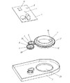
図1は本発明の一実施の形態による回転角度検出装置の平面図、図2は同分解斜視図であり、同図において、1は外周に平歯車部1Aが形成された絶縁樹脂または金属製の回転体で、中央部には挿通するステアリング(図示せず)の軸と係合する係合部1Bが設けられると共に、下面には略円筒状の摺接部1Cが形成されている。
1A 平歯車部
1B 係合部
1C 摺接部
3 第一の検出体
3A 平歯車部
4、6 磁石
5 第二の検出体
5A 平歯車部
7 配線基板
8、9 磁気検出素子
10 制御手段
12 ケース
12A 貫通孔
12B、12C 突出部
13 第一の検出手段
14 第二の検出手段
15、16 ばね
Claims (2)
- 下面に略円筒状の摺接部が形成され、ステアリングに連動して回転する回転体と、貫通孔に上記摺接部が挿通され、上記回転体が回転可能に装着されたケースと、上記回転体に連動して回転する検出体と、この検出体の回転を検出信号として検出する検出手段と、この検出手段からの検出信号により上記回転体の回転角度を検出する制御手段からなり、上記回転体または上記検出体の一方を他方へ押圧する付勢手段を設けると共に、上記ケースの貫通孔に押圧付勢された上記回転体の摺接部が常に当接する複数の突出部を形成した回転角度検出装置。
- 複数の突出部を、付勢手段の押圧方向と対称位置に等間隔で形成した請求項1記載の回転角度検出装置。
Priority Applications (2)
| Application Number | Priority Date | Filing Date | Title |
|---|---|---|---|
| JP2005076812A JP4432809B2 (ja) | 2005-03-17 | 2005-03-17 | 回転角度検出装置 |
| US11/357,978 US7465918B2 (en) | 2005-03-17 | 2006-02-22 | Rotation angle sensor device for detecting rotation angle of a rotary shaft |
Applications Claiming Priority (1)
| Application Number | Priority Date | Filing Date | Title |
|---|---|---|---|
| JP2005076812A JP4432809B2 (ja) | 2005-03-17 | 2005-03-17 | 回転角度検出装置 |
Publications (2)
| Publication Number | Publication Date |
|---|---|
| JP2006258625A JP2006258625A (ja) | 2006-09-28 |
| JP4432809B2 true JP4432809B2 (ja) | 2010-03-17 |
Family
ID=37009351
Family Applications (1)
| Application Number | Title | Priority Date | Filing Date |
|---|---|---|---|
| JP2005076812A Expired - Fee Related JP4432809B2 (ja) | 2005-03-17 | 2005-03-17 | 回転角度検出装置 |
Country Status (2)
| Country | Link |
|---|---|
| US (1) | US7465918B2 (ja) |
| JP (1) | JP4432809B2 (ja) |
Families Citing this family (14)
| Publication number | Priority date | Publication date | Assignee | Title |
|---|---|---|---|---|
| JP5265362B2 (ja) * | 2006-07-25 | 2013-08-14 | エルジー イノテック カンパニー リミテッド | 操向角感知装置及び感知方法 |
| US20090054820A1 (en) * | 2007-02-28 | 2009-02-26 | Weltner Thomas R | Static progressive pronation supination splint |
| JP4992516B2 (ja) * | 2007-04-02 | 2012-08-08 | パナソニック株式会社 | 回転角度検出装置 |
| JP5012181B2 (ja) | 2007-05-07 | 2012-08-29 | パナソニック株式会社 | 回転角度検出装置 |
| US8281687B2 (en) | 2007-07-11 | 2012-10-09 | Panasonic Corporation | Rotation angle detection device |
| JP4998330B2 (ja) * | 2007-07-11 | 2012-08-15 | パナソニック株式会社 | 回転角度検出装置 |
| JP2009063393A (ja) | 2007-09-06 | 2009-03-26 | Panasonic Corp | 回転角度検出装置 |
| US9626900B2 (en) | 2007-10-23 | 2017-04-18 | Japan Display Inc. | Electro-optical device |
| US7579829B1 (en) * | 2008-07-06 | 2009-08-25 | Avago Technologies Ecbu Ip (Singapore) Pte. Ltd. | Inductive multi-turn encoder |
| JP5439773B2 (ja) * | 2008-09-16 | 2014-03-12 | パナソニック株式会社 | 回転角度検出装置 |
| EP2675598B1 (en) * | 2011-02-17 | 2019-07-24 | Abb Ag | Robot member with absolute multiple-revolution encoder |
| JP6007131B2 (ja) | 2013-03-01 | 2016-10-12 | 日立オートモティブシステムズ株式会社 | 操舵角センサおよびこれを用いた電動パワーステアリング装置 |
| DE102015209385A1 (de) * | 2015-05-22 | 2016-11-24 | Robert Bosch Gmbh | Winkelsensor zur Erfassung von Drehwinkeln eines rotierenden Bauteils |
| CN106814204B (zh) * | 2016-12-25 | 2019-01-15 | 重庆市永川区益锐机械有限责任公司 | 回转速度检测装置 |
Family Cites Families (4)
| Publication number | Priority date | Publication date | Assignee | Title |
|---|---|---|---|---|
| JP3587674B2 (ja) * | 1998-01-07 | 2004-11-10 | アルプス電気株式会社 | 回転角度センサ、この回転角度センサを用いたトルクセンサ、このトルクセンサを用いた電動パワーステアリング装置 |
| DE19962241A1 (de) * | 1999-12-22 | 2001-07-12 | Ruf Electronics Gmbh | Positionssensor |
| JP2004184264A (ja) * | 2002-12-04 | 2004-07-02 | Matsushita Electric Ind Co Ltd | 回転角度検出装置 |
| JP2005003625A (ja) | 2003-06-16 | 2005-01-06 | Matsushita Electric Ind Co Ltd | 回転角度検出装置 |
-
2005
- 2005-03-17 JP JP2005076812A patent/JP4432809B2/ja not_active Expired - Fee Related
-
2006
- 2006-02-22 US US11/357,978 patent/US7465918B2/en active Active
Also Published As
| Publication number | Publication date |
|---|---|
| US7465918B2 (en) | 2008-12-16 |
| JP2006258625A (ja) | 2006-09-28 |
| US20060208176A1 (en) | 2006-09-21 |
Similar Documents
| Publication | Publication Date | Title |
|---|---|---|
| JP4992516B2 (ja) | 回転角度検出装置 | |
| JP4432809B2 (ja) | 回転角度検出装置 | |
| CN100383508C (zh) | 转动角度和转矩的检测装置 | |
| CN100551740C (zh) | 旋转角度检测装置 | |
| JP2007139741A (ja) | 回転角度検出装置 | |
| JP5012181B2 (ja) | 回転角度検出装置 | |
| US9335152B2 (en) | Rotation angle detection device | |
| JP2007192609A (ja) | 回転角度検出装置 | |
| JP5130987B2 (ja) | 回転角度検出装置 | |
| JP4415859B2 (ja) | 回転角度検出装置 | |
| JP5439773B2 (ja) | 回転角度検出装置 | |
| JP5574862B2 (ja) | 回転角度検出装置 | |
| JP2013156184A (ja) | 回転角度検出装置 | |
| JP2009063393A (ja) | 回転角度検出装置 | |
| JP6357660B2 (ja) | 回転角度検出装置およびこれを用いた回転角度検出ユニット | |
| JP6056009B2 (ja) | 回転角度検出装置 | |
| JP2012122982A (ja) | 回転角度検出装置および電動パワーステアリング装置 | |
| JP2013200241A (ja) | 回転角度検出装置 | |
| JP2023155639A (ja) | 回転検出装置 | |
| CN1952589A (zh) | 旋转角度检测装置 | |
| JP2013167548A (ja) | 回転角度検出装置及びこれを用いた回転角度検出システム | |
| JP4569044B2 (ja) | 回転角度検出装置 | |
| JP2011099727A (ja) | 回転角度検出装置及びこれを用いた回転角度・トルク検出装置 | |
| JP2010096518A (ja) | 回転角度検出装置 | |
| JP2008070130A (ja) | 回転角度検出装置 |
Legal Events
| Date | Code | Title | Description |
|---|---|---|---|
| A621 | Written request for application examination |
Free format text: JAPANESE INTERMEDIATE CODE: A621 Effective date: 20071106 |
|
| RD01 | Notification of change of attorney |
Free format text: JAPANESE INTERMEDIATE CODE: A7421 Effective date: 20071212 |
|
| A977 | Report on retrieval |
Free format text: JAPANESE INTERMEDIATE CODE: A971007 Effective date: 20091006 |
|
| A131 | Notification of reasons for refusal |
Free format text: JAPANESE INTERMEDIATE CODE: A131 Effective date: 20091013 |
|
| A521 | Request for written amendment filed |
Free format text: JAPANESE INTERMEDIATE CODE: A523 Effective date: 20091106 |
|
| TRDD | Decision of grant or rejection written | ||
| RD01 | Notification of change of attorney |
Free format text: JAPANESE INTERMEDIATE CODE: A7421 Effective date: 20091126 |
|
| A01 | Written decision to grant a patent or to grant a registration (utility model) |
Free format text: JAPANESE INTERMEDIATE CODE: A01 Effective date: 20091201 |
|
| A01 | Written decision to grant a patent or to grant a registration (utility model) |
Free format text: JAPANESE INTERMEDIATE CODE: A01 |
|
| A61 | First payment of annual fees (during grant procedure) |
Free format text: JAPANESE INTERMEDIATE CODE: A61 Effective date: 20091214 |
|
| R151 | Written notification of patent or utility model registration |
Ref document number: 4432809 Country of ref document: JP Free format text: JAPANESE INTERMEDIATE CODE: R151 |
|
| FPAY | Renewal fee payment (event date is renewal date of database) |
Free format text: PAYMENT UNTIL: 20130108 Year of fee payment: 3 |
|
| FPAY | Renewal fee payment (event date is renewal date of database) |
Free format text: PAYMENT UNTIL: 20130108 Year of fee payment: 3 |
|
| LAPS | Cancellation because of no payment of annual fees |