JP4436621B2 - Conical coupling structure of male and female members - Google Patents
Conical coupling structure of male and female members Download PDFInfo
- Publication number
- JP4436621B2 JP4436621B2 JP2003145006A JP2003145006A JP4436621B2 JP 4436621 B2 JP4436621 B2 JP 4436621B2 JP 2003145006 A JP2003145006 A JP 2003145006A JP 2003145006 A JP2003145006 A JP 2003145006A JP 4436621 B2 JP4436621 B2 JP 4436621B2
- Authority
- JP
- Japan
- Prior art keywords
- male
- female
- female member
- coupling structure
- male member
- Prior art date
- Legal status (The legal status is an assumption and is not a legal conclusion. Google has not performed a legal analysis and makes no representation as to the accuracy of the status listed.)
- Expired - Lifetime
Links
- 230000008878 coupling Effects 0.000 title claims description 65
- 238000010168 coupling process Methods 0.000 title claims description 65
- 238000005859 coupling reaction Methods 0.000 title claims description 65
- 239000000463 material Substances 0.000 claims description 25
- 239000000470 constituent Substances 0.000 claims description 13
- 239000002184 metal Substances 0.000 claims description 12
- 239000000919 ceramic Substances 0.000 claims description 4
- 210000004394 hip joint Anatomy 0.000 claims description 4
- 230000006835 compression Effects 0.000 claims description 3
- 238000007906 compression Methods 0.000 claims description 3
- 230000000694 effects Effects 0.000 claims description 3
- 238000006073 displacement reaction Methods 0.000 claims description 2
- 230000005489 elastic deformation Effects 0.000 claims description 2
- 210000002808 connective tissue Anatomy 0.000 description 3
- 210000002414 leg Anatomy 0.000 description 3
- 238000004873 anchoring Methods 0.000 description 2
- 230000004048 modification Effects 0.000 description 2
- 238000012986 modification Methods 0.000 description 2
- 210000000623 ulna Anatomy 0.000 description 2
- OKTJSMMVPCPJKN-UHFFFAOYSA-N Carbon Chemical compound [C] OKTJSMMVPCPJKN-UHFFFAOYSA-N 0.000 description 1
- 238000010276 construction Methods 0.000 description 1
- 229910002804 graphite Inorganic materials 0.000 description 1
- 239000010439 graphite Substances 0.000 description 1
- 210000001624 hip Anatomy 0.000 description 1
- 210000002758 humerus Anatomy 0.000 description 1
- 238000003780 insertion Methods 0.000 description 1
- 230000037431 insertion Effects 0.000 description 1
- 230000035515 penetration Effects 0.000 description 1
- 238000002271 resection Methods 0.000 description 1
- 239000007787 solid Substances 0.000 description 1
- 230000003068 static effect Effects 0.000 description 1
- 239000000758 substrate Substances 0.000 description 1
- 230000000153 supplemental effect Effects 0.000 description 1
- 238000009736 wetting Methods 0.000 description 1
Images





Classifications
-
- A—HUMAN NECESSITIES
- A61—MEDICAL OR VETERINARY SCIENCE; HYGIENE
- A61L—METHODS OR APPARATUS FOR STERILISING MATERIALS OR OBJECTS IN GENERAL; DISINFECTION, STERILISATION OR DEODORISATION OF AIR; CHEMICAL ASPECTS OF BANDAGES, DRESSINGS, ABSORBENT PADS OR SURGICAL ARTICLES; MATERIALS FOR BANDAGES, DRESSINGS, ABSORBENT PADS OR SURGICAL ARTICLES
- A61L27/00—Materials for grafts or prostheses or for coating grafts or prostheses
- A61L27/02—Inorganic materials
- A61L27/08—Carbon ; Graphite
-
- A—HUMAN NECESSITIES
- A61—MEDICAL OR VETERINARY SCIENCE; HYGIENE
- A61F—FILTERS IMPLANTABLE INTO BLOOD VESSELS; PROSTHESES; DEVICES PROVIDING PATENCY TO, OR PREVENTING COLLAPSING OF, TUBULAR STRUCTURES OF THE BODY, e.g. STENTS; ORTHOPAEDIC, NURSING OR CONTRACEPTIVE DEVICES; FOMENTATION; TREATMENT OR PROTECTION OF EYES OR EARS; BANDAGES, DRESSINGS OR ABSORBENT PADS; FIRST-AID KITS
- A61F2/00—Filters implantable into blood vessels; Prostheses, i.e. artificial substitutes or replacements for parts of the body; Appliances for connecting them with the body; Devices providing patency to, or preventing collapsing of, tubular structures of the body, e.g. stents
- A61F2/02—Prostheses implantable into the body
- A61F2/30—Joints
- A61F2/32—Joints for the hip
- A61F2/36—Femoral heads ; Femoral endoprostheses
- A61F2/3609—Femoral heads or necks; Connections of endoprosthetic heads or necks to endoprosthetic femoral shafts
-
- A—HUMAN NECESSITIES
- A61—MEDICAL OR VETERINARY SCIENCE; HYGIENE
- A61F—FILTERS IMPLANTABLE INTO BLOOD VESSELS; PROSTHESES; DEVICES PROVIDING PATENCY TO, OR PREVENTING COLLAPSING OF, TUBULAR STRUCTURES OF THE BODY, e.g. STENTS; ORTHOPAEDIC, NURSING OR CONTRACEPTIVE DEVICES; FOMENTATION; TREATMENT OR PROTECTION OF EYES OR EARS; BANDAGES, DRESSINGS OR ABSORBENT PADS; FIRST-AID KITS
- A61F2/00—Filters implantable into blood vessels; Prostheses, i.e. artificial substitutes or replacements for parts of the body; Appliances for connecting them with the body; Devices providing patency to, or preventing collapsing of, tubular structures of the body, e.g. stents
- A61F2/02—Prostheses implantable into the body
- A61F2/30—Joints
- A61F2/38—Joints for elbows or knees
- A61F2/3804—Joints for elbows or knees for elbows
-
- A—HUMAN NECESSITIES
- A61—MEDICAL OR VETERINARY SCIENCE; HYGIENE
- A61F—FILTERS IMPLANTABLE INTO BLOOD VESSELS; PROSTHESES; DEVICES PROVIDING PATENCY TO, OR PREVENTING COLLAPSING OF, TUBULAR STRUCTURES OF THE BODY, e.g. STENTS; ORTHOPAEDIC, NURSING OR CONTRACEPTIVE DEVICES; FOMENTATION; TREATMENT OR PROTECTION OF EYES OR EARS; BANDAGES, DRESSINGS OR ABSORBENT PADS; FIRST-AID KITS
- A61F2/00—Filters implantable into blood vessels; Prostheses, i.e. artificial substitutes or replacements for parts of the body; Appliances for connecting them with the body; Devices providing patency to, or preventing collapsing of, tubular structures of the body, e.g. stents
- A61F2/02—Prostheses implantable into the body
- A61F2/30—Joints
- A61F2/30767—Special external or bone-contacting surface, e.g. coating for improving bone ingrowth
-
- A—HUMAN NECESSITIES
- A61—MEDICAL OR VETERINARY SCIENCE; HYGIENE
- A61F—FILTERS IMPLANTABLE INTO BLOOD VESSELS; PROSTHESES; DEVICES PROVIDING PATENCY TO, OR PREVENTING COLLAPSING OF, TUBULAR STRUCTURES OF THE BODY, e.g. STENTS; ORTHOPAEDIC, NURSING OR CONTRACEPTIVE DEVICES; FOMENTATION; TREATMENT OR PROTECTION OF EYES OR EARS; BANDAGES, DRESSINGS OR ABSORBENT PADS; FIRST-AID KITS
- A61F2/00—Filters implantable into blood vessels; Prostheses, i.e. artificial substitutes or replacements for parts of the body; Appliances for connecting them with the body; Devices providing patency to, or preventing collapsing of, tubular structures of the body, e.g. stents
- A61F2/02—Prostheses implantable into the body
- A61F2/30—Joints
- A61F2/32—Joints for the hip
- A61F2/36—Femoral heads ; Femoral endoprostheses
-
- A—HUMAN NECESSITIES
- A61—MEDICAL OR VETERINARY SCIENCE; HYGIENE
- A61F—FILTERS IMPLANTABLE INTO BLOOD VESSELS; PROSTHESES; DEVICES PROVIDING PATENCY TO, OR PREVENTING COLLAPSING OF, TUBULAR STRUCTURES OF THE BODY, e.g. STENTS; ORTHOPAEDIC, NURSING OR CONTRACEPTIVE DEVICES; FOMENTATION; TREATMENT OR PROTECTION OF EYES OR EARS; BANDAGES, DRESSINGS OR ABSORBENT PADS; FIRST-AID KITS
- A61F2/00—Filters implantable into blood vessels; Prostheses, i.e. artificial substitutes or replacements for parts of the body; Appliances for connecting them with the body; Devices providing patency to, or preventing collapsing of, tubular structures of the body, e.g. stents
- A61F2/02—Prostheses implantable into the body
- A61F2/30—Joints
- A61F2/32—Joints for the hip
- A61F2/36—Femoral heads ; Femoral endoprostheses
- A61F2/3662—Femoral shafts
-
- A—HUMAN NECESSITIES
- A61—MEDICAL OR VETERINARY SCIENCE; HYGIENE
- A61F—FILTERS IMPLANTABLE INTO BLOOD VESSELS; PROSTHESES; DEVICES PROVIDING PATENCY TO, OR PREVENTING COLLAPSING OF, TUBULAR STRUCTURES OF THE BODY, e.g. STENTS; ORTHOPAEDIC, NURSING OR CONTRACEPTIVE DEVICES; FOMENTATION; TREATMENT OR PROTECTION OF EYES OR EARS; BANDAGES, DRESSINGS OR ABSORBENT PADS; FIRST-AID KITS
- A61F2/00—Filters implantable into blood vessels; Prostheses, i.e. artificial substitutes or replacements for parts of the body; Appliances for connecting them with the body; Devices providing patency to, or preventing collapsing of, tubular structures of the body, e.g. stents
- A61F2/02—Prostheses implantable into the body
- A61F2/30—Joints
- A61F2002/30001—Additional features of subject-matter classified in A61F2/28, A61F2/30 and subgroups thereof
- A61F2002/30003—Material related properties of the prosthesis or of a coating on the prosthesis
- A61F2002/30004—Material related properties of the prosthesis or of a coating on the prosthesis the prosthesis being made from materials having different values of a given property at different locations within the same prosthesis
- A61F2002/30014—Material related properties of the prosthesis or of a coating on the prosthesis the prosthesis being made from materials having different values of a given property at different locations within the same prosthesis differing in elasticity, stiffness or compressibility
-
- A—HUMAN NECESSITIES
- A61—MEDICAL OR VETERINARY SCIENCE; HYGIENE
- A61F—FILTERS IMPLANTABLE INTO BLOOD VESSELS; PROSTHESES; DEVICES PROVIDING PATENCY TO, OR PREVENTING COLLAPSING OF, TUBULAR STRUCTURES OF THE BODY, e.g. STENTS; ORTHOPAEDIC, NURSING OR CONTRACEPTIVE DEVICES; FOMENTATION; TREATMENT OR PROTECTION OF EYES OR EARS; BANDAGES, DRESSINGS OR ABSORBENT PADS; FIRST-AID KITS
- A61F2/00—Filters implantable into blood vessels; Prostheses, i.e. artificial substitutes or replacements for parts of the body; Appliances for connecting them with the body; Devices providing patency to, or preventing collapsing of, tubular structures of the body, e.g. stents
- A61F2/02—Prostheses implantable into the body
- A61F2/30—Joints
- A61F2002/30001—Additional features of subject-matter classified in A61F2/28, A61F2/30 and subgroups thereof
- A61F2002/30316—The prosthesis having different structural features at different locations within the same prosthesis; Connections between prosthetic parts; Special structural features of bone or joint prostheses not otherwise provided for
- A61F2002/30329—Connections or couplings between prosthetic parts, e.g. between modular parts; Connecting elements
- A61F2002/30331—Connections or couplings between prosthetic parts, e.g. between modular parts; Connecting elements made by longitudinally pushing a protrusion into a complementarily-shaped recess, e.g. held by friction fit
- A61F2002/30332—Conically- or frustoconically-shaped protrusion and recess
-
- A—HUMAN NECESSITIES
- A61—MEDICAL OR VETERINARY SCIENCE; HYGIENE
- A61F—FILTERS IMPLANTABLE INTO BLOOD VESSELS; PROSTHESES; DEVICES PROVIDING PATENCY TO, OR PREVENTING COLLAPSING OF, TUBULAR STRUCTURES OF THE BODY, e.g. STENTS; ORTHOPAEDIC, NURSING OR CONTRACEPTIVE DEVICES; FOMENTATION; TREATMENT OR PROTECTION OF EYES OR EARS; BANDAGES, DRESSINGS OR ABSORBENT PADS; FIRST-AID KITS
- A61F2/00—Filters implantable into blood vessels; Prostheses, i.e. artificial substitutes or replacements for parts of the body; Appliances for connecting them with the body; Devices providing patency to, or preventing collapsing of, tubular structures of the body, e.g. stents
- A61F2/02—Prostheses implantable into the body
- A61F2/30—Joints
- A61F2002/30001—Additional features of subject-matter classified in A61F2/28, A61F2/30 and subgroups thereof
- A61F2002/30316—The prosthesis having different structural features at different locations within the same prosthesis; Connections between prosthetic parts; Special structural features of bone or joint prostheses not otherwise provided for
- A61F2002/30329—Connections or couplings between prosthetic parts, e.g. between modular parts; Connecting elements
- A61F2002/30331—Connections or couplings between prosthetic parts, e.g. between modular parts; Connecting elements made by longitudinally pushing a protrusion into a complementarily-shaped recess, e.g. held by friction fit
- A61F2002/30332—Conically- or frustoconically-shaped protrusion and recess
- A61F2002/30339—Double cones, i.e. connecting element having two conical connections, one at each of its opposite ends
-
- A—HUMAN NECESSITIES
- A61—MEDICAL OR VETERINARY SCIENCE; HYGIENE
- A61F—FILTERS IMPLANTABLE INTO BLOOD VESSELS; PROSTHESES; DEVICES PROVIDING PATENCY TO, OR PREVENTING COLLAPSING OF, TUBULAR STRUCTURES OF THE BODY, e.g. STENTS; ORTHOPAEDIC, NURSING OR CONTRACEPTIVE DEVICES; FOMENTATION; TREATMENT OR PROTECTION OF EYES OR EARS; BANDAGES, DRESSINGS OR ABSORBENT PADS; FIRST-AID KITS
- A61F2/00—Filters implantable into blood vessels; Prostheses, i.e. artificial substitutes or replacements for parts of the body; Appliances for connecting them with the body; Devices providing patency to, or preventing collapsing of, tubular structures of the body, e.g. stents
- A61F2/02—Prostheses implantable into the body
- A61F2/30—Joints
- A61F2002/30001—Additional features of subject-matter classified in A61F2/28, A61F2/30 and subgroups thereof
- A61F2002/30316—The prosthesis having different structural features at different locations within the same prosthesis; Connections between prosthetic parts; Special structural features of bone or joint prostheses not otherwise provided for
- A61F2002/30329—Connections or couplings between prosthetic parts, e.g. between modular parts; Connecting elements
- A61F2002/30331—Connections or couplings between prosthetic parts, e.g. between modular parts; Connecting elements made by longitudinally pushing a protrusion into a complementarily-shaped recess, e.g. held by friction fit
- A61F2002/30332—Conically- or frustoconically-shaped protrusion and recess
- A61F2002/30349—Conically- or frustoconically-shaped protrusion and recess the male and female complementary cones being of different conicities, i.e. for reducing the contact area
-
- A—HUMAN NECESSITIES
- A61—MEDICAL OR VETERINARY SCIENCE; HYGIENE
- A61F—FILTERS IMPLANTABLE INTO BLOOD VESSELS; PROSTHESES; DEVICES PROVIDING PATENCY TO, OR PREVENTING COLLAPSING OF, TUBULAR STRUCTURES OF THE BODY, e.g. STENTS; ORTHOPAEDIC, NURSING OR CONTRACEPTIVE DEVICES; FOMENTATION; TREATMENT OR PROTECTION OF EYES OR EARS; BANDAGES, DRESSINGS OR ABSORBENT PADS; FIRST-AID KITS
- A61F2/00—Filters implantable into blood vessels; Prostheses, i.e. artificial substitutes or replacements for parts of the body; Appliances for connecting them with the body; Devices providing patency to, or preventing collapsing of, tubular structures of the body, e.g. stents
- A61F2/02—Prostheses implantable into the body
- A61F2/30—Joints
- A61F2002/30001—Additional features of subject-matter classified in A61F2/28, A61F2/30 and subgroups thereof
- A61F2002/30316—The prosthesis having different structural features at different locations within the same prosthesis; Connections between prosthetic parts; Special structural features of bone or joint prostheses not otherwise provided for
- A61F2002/30329—Connections or couplings between prosthetic parts, e.g. between modular parts; Connecting elements
- A61F2002/30476—Connections or couplings between prosthetic parts, e.g. between modular parts; Connecting elements locked by an additional locking mechanism
- A61F2002/30507—Connections or couplings between prosthetic parts, e.g. between modular parts; Connecting elements locked by an additional locking mechanism using a threaded locking member, e.g. a locking screw or a set screw
-
- A—HUMAN NECESSITIES
- A61—MEDICAL OR VETERINARY SCIENCE; HYGIENE
- A61F—FILTERS IMPLANTABLE INTO BLOOD VESSELS; PROSTHESES; DEVICES PROVIDING PATENCY TO, OR PREVENTING COLLAPSING OF, TUBULAR STRUCTURES OF THE BODY, e.g. STENTS; ORTHOPAEDIC, NURSING OR CONTRACEPTIVE DEVICES; FOMENTATION; TREATMENT OR PROTECTION OF EYES OR EARS; BANDAGES, DRESSINGS OR ABSORBENT PADS; FIRST-AID KITS
- A61F2/00—Filters implantable into blood vessels; Prostheses, i.e. artificial substitutes or replacements for parts of the body; Appliances for connecting them with the body; Devices providing patency to, or preventing collapsing of, tubular structures of the body, e.g. stents
- A61F2/02—Prostheses implantable into the body
- A61F2/30—Joints
- A61F2002/30001—Additional features of subject-matter classified in A61F2/28, A61F2/30 and subgroups thereof
- A61F2002/30316—The prosthesis having different structural features at different locations within the same prosthesis; Connections between prosthetic parts; Special structural features of bone or joint prostheses not otherwise provided for
- A61F2002/30535—Special structural features of bone or joint prostheses not otherwise provided for
- A61F2002/30574—Special structural features of bone or joint prostheses not otherwise provided for with an integral complete or partial collar or flange
-
- A—HUMAN NECESSITIES
- A61—MEDICAL OR VETERINARY SCIENCE; HYGIENE
- A61F—FILTERS IMPLANTABLE INTO BLOOD VESSELS; PROSTHESES; DEVICES PROVIDING PATENCY TO, OR PREVENTING COLLAPSING OF, TUBULAR STRUCTURES OF THE BODY, e.g. STENTS; ORTHOPAEDIC, NURSING OR CONTRACEPTIVE DEVICES; FOMENTATION; TREATMENT OR PROTECTION OF EYES OR EARS; BANDAGES, DRESSINGS OR ABSORBENT PADS; FIRST-AID KITS
- A61F2/00—Filters implantable into blood vessels; Prostheses, i.e. artificial substitutes or replacements for parts of the body; Appliances for connecting them with the body; Devices providing patency to, or preventing collapsing of, tubular structures of the body, e.g. stents
- A61F2/02—Prostheses implantable into the body
- A61F2/30—Joints
- A61F2002/30001—Additional features of subject-matter classified in A61F2/28, A61F2/30 and subgroups thereof
- A61F2002/30316—The prosthesis having different structural features at different locations within the same prosthesis; Connections between prosthetic parts; Special structural features of bone or joint prostheses not otherwise provided for
- A61F2002/30535—Special structural features of bone or joint prostheses not otherwise provided for
- A61F2002/30579—Special structural features of bone or joint prostheses not otherwise provided for with mechanically expandable devices, e.g. fixation devices
-
- A—HUMAN NECESSITIES
- A61—MEDICAL OR VETERINARY SCIENCE; HYGIENE
- A61F—FILTERS IMPLANTABLE INTO BLOOD VESSELS; PROSTHESES; DEVICES PROVIDING PATENCY TO, OR PREVENTING COLLAPSING OF, TUBULAR STRUCTURES OF THE BODY, e.g. STENTS; ORTHOPAEDIC, NURSING OR CONTRACEPTIVE DEVICES; FOMENTATION; TREATMENT OR PROTECTION OF EYES OR EARS; BANDAGES, DRESSINGS OR ABSORBENT PADS; FIRST-AID KITS
- A61F2/00—Filters implantable into blood vessels; Prostheses, i.e. artificial substitutes or replacements for parts of the body; Appliances for connecting them with the body; Devices providing patency to, or preventing collapsing of, tubular structures of the body, e.g. stents
- A61F2/02—Prostheses implantable into the body
- A61F2/30—Joints
- A61F2002/30001—Additional features of subject-matter classified in A61F2/28, A61F2/30 and subgroups thereof
- A61F2002/30316—The prosthesis having different structural features at different locations within the same prosthesis; Connections between prosthetic parts; Special structural features of bone or joint prostheses not otherwise provided for
- A61F2002/30535—Special structural features of bone or joint prostheses not otherwise provided for
- A61F2002/30594—Special structural features of bone or joint prostheses not otherwise provided for slotted, e.g. radial or meridian slot ending in a polar aperture, non-polar slots, horizontal or arcuate slots
-
- A—HUMAN NECESSITIES
- A61—MEDICAL OR VETERINARY SCIENCE; HYGIENE
- A61F—FILTERS IMPLANTABLE INTO BLOOD VESSELS; PROSTHESES; DEVICES PROVIDING PATENCY TO, OR PREVENTING COLLAPSING OF, TUBULAR STRUCTURES OF THE BODY, e.g. STENTS; ORTHOPAEDIC, NURSING OR CONTRACEPTIVE DEVICES; FOMENTATION; TREATMENT OR PROTECTION OF EYES OR EARS; BANDAGES, DRESSINGS OR ABSORBENT PADS; FIRST-AID KITS
- A61F2/00—Filters implantable into blood vessels; Prostheses, i.e. artificial substitutes or replacements for parts of the body; Appliances for connecting them with the body; Devices providing patency to, or preventing collapsing of, tubular structures of the body, e.g. stents
- A61F2/02—Prostheses implantable into the body
- A61F2/30—Joints
- A61F2002/30001—Additional features of subject-matter classified in A61F2/28, A61F2/30 and subgroups thereof
- A61F2002/30316—The prosthesis having different structural features at different locations within the same prosthesis; Connections between prosthetic parts; Special structural features of bone or joint prostheses not otherwise provided for
- A61F2002/30535—Special structural features of bone or joint prostheses not otherwise provided for
- A61F2002/30604—Special structural features of bone or joint prostheses not otherwise provided for modular
-
- A—HUMAN NECESSITIES
- A61—MEDICAL OR VETERINARY SCIENCE; HYGIENE
- A61F—FILTERS IMPLANTABLE INTO BLOOD VESSELS; PROSTHESES; DEVICES PROVIDING PATENCY TO, OR PREVENTING COLLAPSING OF, TUBULAR STRUCTURES OF THE BODY, e.g. STENTS; ORTHOPAEDIC, NURSING OR CONTRACEPTIVE DEVICES; FOMENTATION; TREATMENT OR PROTECTION OF EYES OR EARS; BANDAGES, DRESSINGS OR ABSORBENT PADS; FIRST-AID KITS
- A61F2/00—Filters implantable into blood vessels; Prostheses, i.e. artificial substitutes or replacements for parts of the body; Appliances for connecting them with the body; Devices providing patency to, or preventing collapsing of, tubular structures of the body, e.g. stents
- A61F2/02—Prostheses implantable into the body
- A61F2/30—Joints
- A61F2002/30001—Additional features of subject-matter classified in A61F2/28, A61F2/30 and subgroups thereof
- A61F2002/30316—The prosthesis having different structural features at different locations within the same prosthesis; Connections between prosthetic parts; Special structural features of bone or joint prostheses not otherwise provided for
- A61F2002/30535—Special structural features of bone or joint prostheses not otherwise provided for
- A61F2002/30604—Special structural features of bone or joint prostheses not otherwise provided for modular
- A61F2002/30616—Sets comprising a plurality of prosthetic parts of different sizes or orientations
-
- A—HUMAN NECESSITIES
- A61—MEDICAL OR VETERINARY SCIENCE; HYGIENE
- A61F—FILTERS IMPLANTABLE INTO BLOOD VESSELS; PROSTHESES; DEVICES PROVIDING PATENCY TO, OR PREVENTING COLLAPSING OF, TUBULAR STRUCTURES OF THE BODY, e.g. STENTS; ORTHOPAEDIC, NURSING OR CONTRACEPTIVE DEVICES; FOMENTATION; TREATMENT OR PROTECTION OF EYES OR EARS; BANDAGES, DRESSINGS OR ABSORBENT PADS; FIRST-AID KITS
- A61F2/00—Filters implantable into blood vessels; Prostheses, i.e. artificial substitutes or replacements for parts of the body; Appliances for connecting them with the body; Devices providing patency to, or preventing collapsing of, tubular structures of the body, e.g. stents
- A61F2/02—Prostheses implantable into the body
- A61F2/30—Joints
- A61F2/30767—Special external or bone-contacting surface, e.g. coating for improving bone ingrowth
- A61F2/30771—Special external or bone-contacting surface, e.g. coating for improving bone ingrowth applied in original prostheses, e.g. holes or grooves
- A61F2002/30772—Apertures or holes, e.g. of circular cross section
- A61F2002/30774—Apertures or holes, e.g. of circular cross section internally-threaded
-
- A—HUMAN NECESSITIES
- A61—MEDICAL OR VETERINARY SCIENCE; HYGIENE
- A61F—FILTERS IMPLANTABLE INTO BLOOD VESSELS; PROSTHESES; DEVICES PROVIDING PATENCY TO, OR PREVENTING COLLAPSING OF, TUBULAR STRUCTURES OF THE BODY, e.g. STENTS; ORTHOPAEDIC, NURSING OR CONTRACEPTIVE DEVICES; FOMENTATION; TREATMENT OR PROTECTION OF EYES OR EARS; BANDAGES, DRESSINGS OR ABSORBENT PADS; FIRST-AID KITS
- A61F2/00—Filters implantable into blood vessels; Prostheses, i.e. artificial substitutes or replacements for parts of the body; Appliances for connecting them with the body; Devices providing patency to, or preventing collapsing of, tubular structures of the body, e.g. stents
- A61F2/02—Prostheses implantable into the body
- A61F2/30—Joints
- A61F2/30767—Special external or bone-contacting surface, e.g. coating for improving bone ingrowth
- A61F2/30771—Special external or bone-contacting surface, e.g. coating for improving bone ingrowth applied in original prostheses, e.g. holes or grooves
- A61F2002/30878—Special external or bone-contacting surface, e.g. coating for improving bone ingrowth applied in original prostheses, e.g. holes or grooves with non-sharp protrusions, for instance contacting the bone for anchoring, e.g. keels, pegs, pins, posts, shanks, stems, struts
-
- A—HUMAN NECESSITIES
- A61—MEDICAL OR VETERINARY SCIENCE; HYGIENE
- A61F—FILTERS IMPLANTABLE INTO BLOOD VESSELS; PROSTHESES; DEVICES PROVIDING PATENCY TO, OR PREVENTING COLLAPSING OF, TUBULAR STRUCTURES OF THE BODY, e.g. STENTS; ORTHOPAEDIC, NURSING OR CONTRACEPTIVE DEVICES; FOMENTATION; TREATMENT OR PROTECTION OF EYES OR EARS; BANDAGES, DRESSINGS OR ABSORBENT PADS; FIRST-AID KITS
- A61F2/00—Filters implantable into blood vessels; Prostheses, i.e. artificial substitutes or replacements for parts of the body; Appliances for connecting them with the body; Devices providing patency to, or preventing collapsing of, tubular structures of the body, e.g. stents
- A61F2/02—Prostheses implantable into the body
- A61F2/30—Joints
- A61F2/30767—Special external or bone-contacting surface, e.g. coating for improving bone ingrowth
- A61F2/30771—Special external or bone-contacting surface, e.g. coating for improving bone ingrowth applied in original prostheses, e.g. holes or grooves
- A61F2002/30904—Special external or bone-contacting surface, e.g. coating for improving bone ingrowth applied in original prostheses, e.g. holes or grooves serrated profile, i.e. saw-toothed
-
- A—HUMAN NECESSITIES
- A61—MEDICAL OR VETERINARY SCIENCE; HYGIENE
- A61F—FILTERS IMPLANTABLE INTO BLOOD VESSELS; PROSTHESES; DEVICES PROVIDING PATENCY TO, OR PREVENTING COLLAPSING OF, TUBULAR STRUCTURES OF THE BODY, e.g. STENTS; ORTHOPAEDIC, NURSING OR CONTRACEPTIVE DEVICES; FOMENTATION; TREATMENT OR PROTECTION OF EYES OR EARS; BANDAGES, DRESSINGS OR ABSORBENT PADS; FIRST-AID KITS
- A61F2/00—Filters implantable into blood vessels; Prostheses, i.e. artificial substitutes or replacements for parts of the body; Appliances for connecting them with the body; Devices providing patency to, or preventing collapsing of, tubular structures of the body, e.g. stents
- A61F2/02—Prostheses implantable into the body
- A61F2/30—Joints
- A61F2/32—Joints for the hip
- A61F2/36—Femoral heads ; Femoral endoprostheses
- A61F2/3609—Femoral heads or necks; Connections of endoprosthetic heads or necks to endoprosthetic femoral shafts
- A61F2002/3611—Heads or epiphyseal parts of femur
-
- A—HUMAN NECESSITIES
- A61—MEDICAL OR VETERINARY SCIENCE; HYGIENE
- A61F—FILTERS IMPLANTABLE INTO BLOOD VESSELS; PROSTHESES; DEVICES PROVIDING PATENCY TO, OR PREVENTING COLLAPSING OF, TUBULAR STRUCTURES OF THE BODY, e.g. STENTS; ORTHOPAEDIC, NURSING OR CONTRACEPTIVE DEVICES; FOMENTATION; TREATMENT OR PROTECTION OF EYES OR EARS; BANDAGES, DRESSINGS OR ABSORBENT PADS; FIRST-AID KITS
- A61F2/00—Filters implantable into blood vessels; Prostheses, i.e. artificial substitutes or replacements for parts of the body; Appliances for connecting them with the body; Devices providing patency to, or preventing collapsing of, tubular structures of the body, e.g. stents
- A61F2/02—Prostheses implantable into the body
- A61F2/30—Joints
- A61F2/32—Joints for the hip
- A61F2/36—Femoral heads ; Femoral endoprostheses
- A61F2/3609—Femoral heads or necks; Connections of endoprosthetic heads or necks to endoprosthetic femoral shafts
- A61F2002/3625—Necks
-
- A—HUMAN NECESSITIES
- A61—MEDICAL OR VETERINARY SCIENCE; HYGIENE
- A61F—FILTERS IMPLANTABLE INTO BLOOD VESSELS; PROSTHESES; DEVICES PROVIDING PATENCY TO, OR PREVENTING COLLAPSING OF, TUBULAR STRUCTURES OF THE BODY, e.g. STENTS; ORTHOPAEDIC, NURSING OR CONTRACEPTIVE DEVICES; FOMENTATION; TREATMENT OR PROTECTION OF EYES OR EARS; BANDAGES, DRESSINGS OR ABSORBENT PADS; FIRST-AID KITS
- A61F2/00—Filters implantable into blood vessels; Prostheses, i.e. artificial substitutes or replacements for parts of the body; Appliances for connecting them with the body; Devices providing patency to, or preventing collapsing of, tubular structures of the body, e.g. stents
- A61F2/02—Prostheses implantable into the body
- A61F2/30—Joints
- A61F2/32—Joints for the hip
- A61F2/36—Femoral heads ; Femoral endoprostheses
- A61F2/3609—Femoral heads or necks; Connections of endoprosthetic heads or necks to endoprosthetic femoral shafts
- A61F2002/365—Connections of heads to necks
-
- A—HUMAN NECESSITIES
- A61—MEDICAL OR VETERINARY SCIENCE; HYGIENE
- A61F—FILTERS IMPLANTABLE INTO BLOOD VESSELS; PROSTHESES; DEVICES PROVIDING PATENCY TO, OR PREVENTING COLLAPSING OF, TUBULAR STRUCTURES OF THE BODY, e.g. STENTS; ORTHOPAEDIC, NURSING OR CONTRACEPTIVE DEVICES; FOMENTATION; TREATMENT OR PROTECTION OF EYES OR EARS; BANDAGES, DRESSINGS OR ABSORBENT PADS; FIRST-AID KITS
- A61F2/00—Filters implantable into blood vessels; Prostheses, i.e. artificial substitutes or replacements for parts of the body; Appliances for connecting them with the body; Devices providing patency to, or preventing collapsing of, tubular structures of the body, e.g. stents
- A61F2/02—Prostheses implantable into the body
- A61F2/30—Joints
- A61F2/38—Joints for elbows or knees
- A61F2/3804—Joints for elbows or knees for elbows
- A61F2002/3827—Radial components
-
- A—HUMAN NECESSITIES
- A61—MEDICAL OR VETERINARY SCIENCE; HYGIENE
- A61F—FILTERS IMPLANTABLE INTO BLOOD VESSELS; PROSTHESES; DEVICES PROVIDING PATENCY TO, OR PREVENTING COLLAPSING OF, TUBULAR STRUCTURES OF THE BODY, e.g. STENTS; ORTHOPAEDIC, NURSING OR CONTRACEPTIVE DEVICES; FOMENTATION; TREATMENT OR PROTECTION OF EYES OR EARS; BANDAGES, DRESSINGS OR ABSORBENT PADS; FIRST-AID KITS
- A61F2/00—Filters implantable into blood vessels; Prostheses, i.e. artificial substitutes or replacements for parts of the body; Appliances for connecting them with the body; Devices providing patency to, or preventing collapsing of, tubular structures of the body, e.g. stents
- A61F2/02—Prostheses implantable into the body
- A61F2/30—Joints
- A61F2/38—Joints for elbows or knees
- A61F2/3804—Joints for elbows or knees for elbows
- A61F2002/3831—Ulnar components
-
- A—HUMAN NECESSITIES
- A61—MEDICAL OR VETERINARY SCIENCE; HYGIENE
- A61F—FILTERS IMPLANTABLE INTO BLOOD VESSELS; PROSTHESES; DEVICES PROVIDING PATENCY TO, OR PREVENTING COLLAPSING OF, TUBULAR STRUCTURES OF THE BODY, e.g. STENTS; ORTHOPAEDIC, NURSING OR CONTRACEPTIVE DEVICES; FOMENTATION; TREATMENT OR PROTECTION OF EYES OR EARS; BANDAGES, DRESSINGS OR ABSORBENT PADS; FIRST-AID KITS
- A61F2220/00—Fixations or connections for prostheses classified in groups A61F2/00 - A61F2/26 or A61F2/82 or A61F9/00 or A61F11/00 or subgroups thereof
- A61F2220/0025—Connections or couplings between prosthetic parts, e.g. between modular parts; Connecting elements
-
- A—HUMAN NECESSITIES
- A61—MEDICAL OR VETERINARY SCIENCE; HYGIENE
- A61F—FILTERS IMPLANTABLE INTO BLOOD VESSELS; PROSTHESES; DEVICES PROVIDING PATENCY TO, OR PREVENTING COLLAPSING OF, TUBULAR STRUCTURES OF THE BODY, e.g. STENTS; ORTHOPAEDIC, NURSING OR CONTRACEPTIVE DEVICES; FOMENTATION; TREATMENT OR PROTECTION OF EYES OR EARS; BANDAGES, DRESSINGS OR ABSORBENT PADS; FIRST-AID KITS
- A61F2220/00—Fixations or connections for prostheses classified in groups A61F2/00 - A61F2/26 or A61F2/82 or A61F9/00 or A61F11/00 or subgroups thereof
- A61F2220/0025—Connections or couplings between prosthetic parts, e.g. between modular parts; Connecting elements
- A61F2220/0033—Connections or couplings between prosthetic parts, e.g. between modular parts; Connecting elements made by longitudinally pushing a protrusion into a complementary-shaped recess, e.g. held by friction fit
-
- A—HUMAN NECESSITIES
- A61—MEDICAL OR VETERINARY SCIENCE; HYGIENE
- A61F—FILTERS IMPLANTABLE INTO BLOOD VESSELS; PROSTHESES; DEVICES PROVIDING PATENCY TO, OR PREVENTING COLLAPSING OF, TUBULAR STRUCTURES OF THE BODY, e.g. STENTS; ORTHOPAEDIC, NURSING OR CONTRACEPTIVE DEVICES; FOMENTATION; TREATMENT OR PROTECTION OF EYES OR EARS; BANDAGES, DRESSINGS OR ABSORBENT PADS; FIRST-AID KITS
- A61F2250/00—Special features of prostheses classified in groups A61F2/00 - A61F2/26 or A61F2/82 or A61F9/00 or A61F11/00 or subgroups thereof
- A61F2250/0014—Special features of prostheses classified in groups A61F2/00 - A61F2/26 or A61F2/82 or A61F9/00 or A61F11/00 or subgroups thereof having different values of a given property or geometrical feature, e.g. mechanical property or material property, at different locations within the same prosthesis
- A61F2250/0018—Special features of prostheses classified in groups A61F2/00 - A61F2/26 or A61F2/82 or A61F9/00 or A61F11/00 or subgroups thereof having different values of a given property or geometrical feature, e.g. mechanical property or material property, at different locations within the same prosthesis differing in elasticity, stiffness or compressibility
-
- A—HUMAN NECESSITIES
- A61—MEDICAL OR VETERINARY SCIENCE; HYGIENE
- A61F—FILTERS IMPLANTABLE INTO BLOOD VESSELS; PROSTHESES; DEVICES PROVIDING PATENCY TO, OR PREVENTING COLLAPSING OF, TUBULAR STRUCTURES OF THE BODY, e.g. STENTS; ORTHOPAEDIC, NURSING OR CONTRACEPTIVE DEVICES; FOMENTATION; TREATMENT OR PROTECTION OF EYES OR EARS; BANDAGES, DRESSINGS OR ABSORBENT PADS; FIRST-AID KITS
- A61F2310/00—Prostheses classified in A61F2/28 or A61F2/30 - A61F2/44 being constructed from or coated with a particular material
- A61F2310/00005—The prosthesis being constructed from a particular material
- A61F2310/00011—Metals or alloys
-
- A—HUMAN NECESSITIES
- A61—MEDICAL OR VETERINARY SCIENCE; HYGIENE
- A61F—FILTERS IMPLANTABLE INTO BLOOD VESSELS; PROSTHESES; DEVICES PROVIDING PATENCY TO, OR PREVENTING COLLAPSING OF, TUBULAR STRUCTURES OF THE BODY, e.g. STENTS; ORTHOPAEDIC, NURSING OR CONTRACEPTIVE DEVICES; FOMENTATION; TREATMENT OR PROTECTION OF EYES OR EARS; BANDAGES, DRESSINGS OR ABSORBENT PADS; FIRST-AID KITS
- A61F2310/00—Prostheses classified in A61F2/28 or A61F2/30 - A61F2/44 being constructed from or coated with a particular material
- A61F2310/00005—The prosthesis being constructed from a particular material
- A61F2310/00161—Carbon; Graphite
-
- A—HUMAN NECESSITIES
- A61—MEDICAL OR VETERINARY SCIENCE; HYGIENE
- A61F—FILTERS IMPLANTABLE INTO BLOOD VESSELS; PROSTHESES; DEVICES PROVIDING PATENCY TO, OR PREVENTING COLLAPSING OF, TUBULAR STRUCTURES OF THE BODY, e.g. STENTS; ORTHOPAEDIC, NURSING OR CONTRACEPTIVE DEVICES; FOMENTATION; TREATMENT OR PROTECTION OF EYES OR EARS; BANDAGES, DRESSINGS OR ABSORBENT PADS; FIRST-AID KITS
- A61F2310/00—Prostheses classified in A61F2/28 or A61F2/30 - A61F2/44 being constructed from or coated with a particular material
- A61F2310/00005—The prosthesis being constructed from a particular material
- A61F2310/00161—Carbon; Graphite
- A61F2310/00173—Graphite
-
- A—HUMAN NECESSITIES
- A61—MEDICAL OR VETERINARY SCIENCE; HYGIENE
- A61F—FILTERS IMPLANTABLE INTO BLOOD VESSELS; PROSTHESES; DEVICES PROVIDING PATENCY TO, OR PREVENTING COLLAPSING OF, TUBULAR STRUCTURES OF THE BODY, e.g. STENTS; ORTHOPAEDIC, NURSING OR CONTRACEPTIVE DEVICES; FOMENTATION; TREATMENT OR PROTECTION OF EYES OR EARS; BANDAGES, DRESSINGS OR ABSORBENT PADS; FIRST-AID KITS
- A61F2310/00—Prostheses classified in A61F2/28 or A61F2/30 - A61F2/44 being constructed from or coated with a particular material
- A61F2310/00005—The prosthesis being constructed from a particular material
- A61F2310/00179—Ceramics or ceramic-like structures
-
- A—HUMAN NECESSITIES
- A61—MEDICAL OR VETERINARY SCIENCE; HYGIENE
- A61F—FILTERS IMPLANTABLE INTO BLOOD VESSELS; PROSTHESES; DEVICES PROVIDING PATENCY TO, OR PREVENTING COLLAPSING OF, TUBULAR STRUCTURES OF THE BODY, e.g. STENTS; ORTHOPAEDIC, NURSING OR CONTRACEPTIVE DEVICES; FOMENTATION; TREATMENT OR PROTECTION OF EYES OR EARS; BANDAGES, DRESSINGS OR ABSORBENT PADS; FIRST-AID KITS
- A61F2310/00—Prostheses classified in A61F2/28 or A61F2/30 - A61F2/44 being constructed from or coated with a particular material
- A61F2310/00389—The prosthesis being coated or covered with a particular material
- A61F2310/00574—Coating or prosthesis-covering structure made of carbon, e.g. of pyrocarbon
Landscapes
- Health & Medical Sciences (AREA)
- Orthopedic Medicine & Surgery (AREA)
- General Health & Medical Sciences (AREA)
- Animal Behavior & Ethology (AREA)
- Veterinary Medicine (AREA)
- Oral & Maxillofacial Surgery (AREA)
- Transplantation (AREA)
- Public Health (AREA)
- Life Sciences & Earth Sciences (AREA)
- Cardiology (AREA)
- Chemical & Material Sciences (AREA)
- Engineering & Computer Science (AREA)
- Biomedical Technology (AREA)
- Heart & Thoracic Surgery (AREA)
- Vascular Medicine (AREA)
- Epidemiology (AREA)
- Medicinal Chemistry (AREA)
- Inorganic Chemistry (AREA)
- Physical Education & Sports Medicine (AREA)
- Dermatology (AREA)
- Prostheses (AREA)
Description
【0001】
【発明の属する技術分野】
本発明は、特に軸方向の圧縮荷重を受けるようになった雄型部材と雌型部材の円錐結合構造に関する。本発明の結合構造は、特に医用人工装具(プロテーゼ)の分野で利用されるが、これには限定されない。
【0002】
【従来の技術及び発明が解決しようとする課題】
円錐形タイプの結合構造、例えば、モースコーン(Morse cone)は、2つの部品を簡単且つ分解可能な仕方で互いに組み付ける周知の解決策である。円錐結合構造は、図1に示すように、一般に金属製の雄型部材1と雌型部材2によって構成されている。雄型部材1は、コーン又は円錐形部分3を有し、このコーン又は円錐形部分は、これと対応関係をなす雌型部材2の円錐形凹部4と嵌合する。雄型部材1及び雌型部材2は、これらが結合位置にあるとき、間隙e1,e2がそれぞれ、雄型部材1のコーン3の遠位端部と雌型部材2の円錐形凹部4の底部との間及び雌型部材2のベース5と雄型部材1の上面又は肩6との間に生じたままであって、それにより凹部4内でのコーン3の食込み効果(wedging )を得る一方で結合構造を超静圧(hyperstatic )にするのを回避するよう設計されている。これら間隙e1,e2は、結合構造の使用範囲全体にわたって存続しなければならない。換言すると、雄型部材1及び雌型部材2は、結合構造に加わる軸方向荷重がどれほどのものであっても雌型部材2内への雄型部材1の侵入力に抵抗するよう設計されている。
【0003】
この種の結合構造により、雌型部材に対する雄型部材の効果的な心出しが得られると共に雌型部材に対する雄型部材の回転が阻止されるようになる。しかしながら、これには、引張抵抗が非常に高い材料で雌型部材を製作する必要がある。確かに、結合構造を形成するため、即ち、雄型部材と雌型部材を互いに組み付けるのに必要なコーン3の角度及び軸方向圧縮力に鑑みて、コーン3と接触状態にある雌型部材の下方部分は永続的に引張力Tを受け、この引張力は、使用中、結合構造が軸方向圧縮荷重Fを受けると増大する。
【0004】
したがって、かかる結合構造は、金属で作られ、かくして、非常に高い引張抵抗を備えた雄型部材及び雌型部材に適しているが、かかる結合構造の原理は、結合構造が大きな軸方向圧縮力F、例えば、或る特定の人工装具が受ける大きな軸方向圧縮荷重を受け、その雌型部材の構成材料の引張抵抗が低いような用途に適用するのは困難であると思われる。かかる場合、確かに、雌型部材は、雌型部材の構成材料の最大引張強さ限度を超えるとすぐに引張力Tの作用を受けてその下方部分のところが破断することになる。
【0005】
本発明は、雌型部材が従来型円錐結合構造において一般に用いられている材料とは異なる材料で作られていて、軸方向圧縮荷重が結合構造に加えられた場合でも雌型部材の受ける引張力を制限できる円錐結合構造を提供することを目的とする。
【0006】
【課題を解決するための手段】
このため、本発明によれば、雄型部材のコーンがこれと対応関係をなして雌型部材に形成された凹部の切頭円錐形部分と嵌合する雄型部材と雌型部材の円錐結合構造において、雌型部材は、ヤング率がせいぜい約35GPaに等しく且つせいぜい雄型部材の構成材料のヤング率に等しい材料で作られ、結合構造の軸線に垂直な雄型部材の表面が、これ又結合構造の軸線に垂直な雌型部材の表面に接触していて、雄型部材と雌型部材が互いに軸方向に当接するようになっていることを特徴とする円錐結合構造が提供される。
【0007】
かくして、本発明の結合構造では、間隙が雄型部材と雌型部材との間に必然的に残される従来型円錐結合構造とは対照的に、雄型部材と雌型部材は互いに軸方向に当接する。かくして、雌型部材によって支持される引張力の大きさは、一定のままであり、特に、結合構造が大きさの漸増する軸方向圧縮荷重を受けても増大しない。したがって、雌型部材を引張抵抗の低い材料で作ることができる。
【0008】
雄型部材と雌型部材の連結がわざわざ超静圧であるようにするこの解決策は、雌型部材の固有のレジリエンスにより、換言すると、雌型部材の構成材料のヤング率が低いこと、即ち、約35GPa以下であるということ、及び雌型部材が雄型部材と少なくとも同じほど弾性であるということによって実現可能になる。これらの特性により、確かに、雌型部材は、雄型部材とのその組立て中、対応関係にある凹部内でのコーンの食込み効果を達成した後でも弾性変形により雄型部材のコーン沿いに雄型部材に向かって軸方向に動くことができる。雄型部材及び雌型部材を、雌型部材の構成材料の最大引張強さ限度を超える前に雌型部材が雄型部材に軸方向に当接するよう寸法決めすることによって、雄型部材のコーンが雌型部材の凹部内に食い込み、かくして、この凹部内に心出しされて回転が阻止され、しかも、雌型部材の受ける引張力が上述の最大限度よりも低い一定の値に制限されたままである円錐結合構造を得ることができる。
【0009】
本発明の結合構造の代表的な実施形態では、雌型部材は、ピロカーボンで作られ、雄型部材は、金属、セラミック又はピロカーボンで作られる。
【0010】
本発明は又、上述した結合構造を有する人工装具であって、結合構造の雌型部材は、人工装具のヘッドを構成し、雄型部材は、人工装具のネックを構成し、人工装具は、テールを更に有している人工装具、例えば、人工とう骨頭、人工尺骨頭又は人工股関節部を提供する。
本発明は更に、上述した結合構造を構成できる1組の雄型部材と雌型部材を提供することを目的としている。
【0011】
この目的のため、本発明によれば、1組の雄型部材と雌型部材であって、雄型部材は、雌型部材に形成された凹部の切頭円錐形部分と嵌合するようになったコーンを有し、雌型部材は、ヤング率がせいぜい約35GPaに等しく且つせいぜい雄型部材の構成材料のヤング率に等しい材料で作られ、雄型部材は、コーンの軸線に垂直な当接面を有し、雄型部材と雌型部材は、コーンを凹部の切頭円錐形部分と嵌合させることにより互いに結合され、この結合構造に加えられた軸方向圧縮荷重の作用下において、上記嵌合に起因して生じる凹部内へのコーンの食込み効果が得られた後、雌型部材の弾性変形により雄型部材に対する雌型部材の軸方向変位が生じると、雌型部材の構成材料の最大引張強さ限度を超える前に、雌型部材が雄型部材の当接面に当接できるように寸法決めされていることを特徴とする1組の雄型部材と雌型部材が提供される。本発明の他の特徴及び利点は、添付の図面を参照して行われる本発明の幾つかの実施形態についての以下の詳細な説明から明らかになろう。
【0012】
【発明の実施の形態】
以下の説明の全体にわたり、特許請求範囲の記載で用いられている「嵌合(又は、嵌入)」は、雌型部材内での雄型部材の動きを封じる調整状態を意味している。
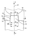
図2は、本発明の第1の実施形態の円錐結合構造又は嵌合構造を示している。この結合構造は、雄型部材10と、雌型部材11とから成る。雌型部材11は、ヤング率又は弾性率が約35GPa以下、例えば、約10GPa〜35GPa、であり雄型部材10の構成材料のヤング率以下の材料で作られている。一例を挙げると、雌型部材11をピロカーボンで作り、雄型部材10を金属、セラミック又はピロカーボンで作るのがよい。好ましくは、雌型部材11の構成材料は、その引張強さよりも高い圧縮強さ(単位はMPaで表される)を有している。
【0013】
雄型部材10は、コーン12と、結合構造の軸線A1、即ち、コーン12の軸線に垂直な当接面として働く肩13とを有している。コーン12は、雌型部材11に対応関係をなして設けられた凹部14内に、この凹部の切頭円錐形部分15に嵌入することによって食い込む。好ましくは、凹部14は、コーン12と接触状態にある切頭円錐形部分15に加えて、切頭円錐形部分15の小径端部からの切頭円錐形部分15に続く余裕分として凹部14の底部に隣接して位置し、雄型コーン12の遠位端部12′の直径d2以上の直径d1をもつ円錐形間隙部分16を有している。円錐形間隙部分16は、図2に示すように雄型コーン12の遠位端部12′を受け入れるのに役立つ。間隙部分16内への雄型コーン12のコーン遠位端部12の挿入を可能にするため、切頭円錐形部分15の小径d3も又、直径d2以上である。
【0014】
雄型コーン12の角度αは、凹部14の切頭円錐形部分15の角度と実質的に同一である。この角度は、凹部14内での雄型コーン12の嵌合状態をユーザが適度な力を及ぼすことにより解くことができるほど十分に大きく、しかも雄型部材10と雌型部材11が互いに対してしっかりと動きが封じられた状態のままであって、雌型部材がその弾性のためにコーン12に沿ってせり上がることにより雄型部材10から弛むことがないほど十分小さいものであるように選択されている。実際には、特にピロカーボンで作られた雌型部材の場合、テーパ角度αは代表的には、2.5°〜5°であり、好ましくは約4°である。
【0015】
雌型部材11のベース又は近位端面17は、雄型部材10の肩13と接触状態にある。かくして、雌型部材11の受ける引張力Tの強さは、一定のままであり、これは、結合組織が可変強さの軸方向圧縮荷重Fを受けた場合でも一定のままである。
【0016】
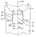
図2の結合構造を得るには、雄型部材10と雌型部材11を、雄型コーン12が雌型部材11の凹部14に食い込んで図3に示すように雄型部材と雌型部材を互いに対して固定するように互いに組み立て、次に、追加の又は補足的な軸方向圧縮荷重を加えて雌型部材11のベース17が肩13に当接するまで雌型部材11を雄型部材10に対して軸方向に変位させる。この軸方向変位中、凹部14が形成されている雌型部材11の底部は、拡張し、かくして、テーパ角度αが設けられているので漸増強さの引張力を受けるが、これら引張力は、雌型部材11が肩13にいったん接触すると、もはや増大しない。コーン12及びこれと対応関係を成す凹部14の寸法形状は、雌型部材11の構成材料の最大引張強さ限度を超える前に、雌型部材11のベース17が肩13に当接できるように選択されている。
【0017】
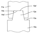
図4は、本発明の第2の実施形態の円錐結合構造を示している。この結合構造は、雄型部材10aの当接面が、肩13aによっては構成されておらず、雌型部材11aの凹部14aの底部14a′と接触状態にあるコーン12aの遠位端面12a′によって構成されている点において図2に示す結合構造とは異なっている。この第2の実施形態の結合構造は、ベースの幅が狭い雌型部材に一層適している。これは、第1の実施形態の結合構造と同じようなやり方で得られる。
【0018】
図5〜図10は、上述の結合原理を用いた人工装具を示している。
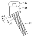
図5には、人工とう骨頭が示されている。この人工装具は、ピロカーボン製ヘッド20、金属製ネック21及び金属製テール(尾部)22によって構成されている。ヘッド20を構成するピロカーボンは、中実一体もの又は黒鉛基材に被着されたピロカーボンの被膜の形態をしている。ヘッド20は、とう骨頭に置き換わるようになっており、テール22は、とう骨(radius)に設けられた穴に導入されるようになっている。
【0019】
ヘッド20とネック21は一緒になって図2に示すタイプの結合構造を形成し、ヘッド20は、少なくとも一部は切頭円錐形の凹部を備えた雌型部材の役割を果たし、雄型部材のネック21は、コーン及び雌型部材が当接する肩又は当接面(図6参照)を有している。しかしながら、この結合構造は、変形例として、図4に示すタイプのものであってもよい。
【0020】
テール22は、従来型円錐形連結構造によってネック21に結合され、雌型部材、即ち、テール22の凹部の底部と雄型部材、即ち、ネック21のコーンの遠位端部との間及び雌型部材のベースと雄型部材の肩との間には間隙が生じている(基準間隔e3,e4を参照のこと)。
【0021】
このモジュール設計の組立体により、人工装具の各要素20,21,22は、互換性がある。かくして、各要素20,21,22を、種々のサイズに設計でき、これら要素は、そのサイズがたとえどのようなものであっても、同一の寸法形状の凹部又は雄型コーンを有することができ、従って、人工装具の所与の要素を別の寸法の同一要素に交換できるようになっている。かくして、外科医は、ヘッド及びテールのそれぞれの寸法を或る特定の患者についていったん選択しても、上腕骨(humerus)及び尺骨(cubitus )に対するヘッドの最適な位置決め状態が得られるようネックの寸法を選択することができる。
【0022】
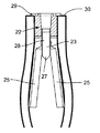
本発明の人工とう骨頭の別の特徴によれば、とう骨に設けられた穴内への人工装具の効果的な繋留を行うために、テール22は有利には、ねじ23を図8に示すようにこの中に挿入すると、横方向に拡開するようになった拡張可能なピンの形態をしている。テール22は、ねじ23の導入及び螺入を可能にする螺設部分と、テールの拡開可能な部分を構成する弾性変形可能な脚部25及びねじ23の導入中、脚部25を互いに離隔させるようねじ23の円錐形遠位部分27と相互作用すると共にねじ23の導入をいったん完了すると脚部25を離隔位置に固定するようねじ23の円筒形部分28と相互作用するようになった内部突起26を有している(図7及び図8を参照のこと)。とう骨の切除表面30に当接するようになったフランジ29が、テール22の近位端部の高さ位置に更に設けられている。テール22の外面31は、図5及び図6に示すように、とう骨の穴内へのこのテール22の繋留の度合いを一層高めるよう好ましくは切込み付きである。
【0023】
図9は、尺骨頭の人工装具を示している。この人工装具は、尺骨頭に置き換わるようになったピロカーボン製ヘッド40、金属製ネック41及び尺骨に設けられた穴に導入されるようになった金属製テール42によって構成されている。ヘッド40とネック41は、図2に示すタイプの結合構造を形成している。しかしながら、この結合構造は、図4に示すタイプのものであってもよい。ネック41とテール42は、従来型円錐結合構造により互いに結合される。
【0024】
図10は、ピロカーボン製ヘッド50、金属製ネック51及び金属製テール52によって構成された股関節部(hip )の人工装具、即ち、人工股関節部を示している。ネック51及びテール52は好ましくは、単一部品組立体を形成している。ヘッド50及びネック51は、図2の結合構造又は、変形例として図4の結合構造と性能が同等の結合構造を形成している。
【図面の簡単な説明】
【図1】従来技術の円錐結合構造の断面図である。
【図2】図1の第1の実施形態の円錐結合構造の断面図である。
【図3】本発明の第1の実施形態の結合構造の中間状態を示す断面図である。
【図4】本発明の第2の実施形態の円錐結合構造を示す断面図である。
【図5】本発明の結合構造を用いた人工とう骨頭を示す分解平面図である。
【図6】組立て状態の図5の人工装具を示す平面図である。
【図7】図6に示す人工装具のテールを構成する拡張ピンを示す断面図である。
【図8】とう骨に挿入された図7の拡張ピンを示す断面図である。
【図9】本発明の結合組織を用いる人工尺骨頭を示す平面図である。
【図10】本発明の結合組織を用いる人工股関節部を示す平面図である。
【符号の説明】
10 雄型部材
11 雌型部材
12 コーン
13 当接面
14 凹部
15 切頭円錐形部分
16 円錐形間隙部分
A1 円錐結合構造の軸線[0001]
BACKGROUND OF THE INVENTION
The present invention particularly relates to a conical coupling structure of a male member and a female member which is adapted to receive an axial compressive load. The coupling structure of the present invention is used particularly in the field of medical prostheses (prostheses), but is not limited thereto.
[0002]
[Prior art and problems to be solved by the invention]
A conical type coupling structure, such as a Morse cone, is a well-known solution for assembling two parts together in a simple and resolvable manner. As shown in FIG. 1, the conical coupling structure is generally constituted by a
[0003]
This type of coupling structure provides effective centering of the male member relative to the female member and prevents rotation of the male member relative to the female member. However, this requires that the female member be made of a material having a very high tensile resistance. Certainly, in view of the angle of the
[0004]
Therefore, such a coupling structure is made of metal and thus suitable for male and female members with very high tensile resistance, but the principle of such coupling structure is that the coupling structure has a large axial compressive force. F, for example, it may be difficult to apply to applications where a certain prosthetic device is subjected to a large axial compressive load and the tensile resistance of the material of the female member is low. In such a case, the female member is surely subjected to the action of the tensile force T as soon as the maximum tensile strength limit of the constituent material of the female member is exceeded, and the lower portion thereof is broken.
[0005]
The present invention provides that the female member is made of a material that is different from the material commonly used in conventional conical coupling structures, and the tensile force received by the female member even when an axial compressive load is applied to the coupling structure. An object of the present invention is to provide a conical coupling structure that can limit the above.
[0006]
[Means for Solving the Problems]
For this reason, according to the present invention, the cone of the male member and the female member are fitted into the truncated conical portion of the recess formed in the female member so that the cone of the male member has a corresponding relationship therewith. In construction, the female member is made of a material whose Young's modulus is at most equal to about 35 GPa and at most equal to the Young's modulus of the constituent material of the male member, and the surface of the male member perpendicular to the axis of the coupling structure is also A conical coupling structure is provided that contacts the surface of the female member perpendicular to the axis of the coupling structure, such that the male member and the female member are in axial contact with each other.
[0007]
Thus, in the coupling structure of the present invention, the male member and the female member are axially opposite each other, in contrast to the conventional conical coupling structure in which a gap is necessarily left between the male member and the female member. Abut. Thus, the magnitude of the tensile force supported by the female member remains constant, and in particular does not increase when the coupling structure is subjected to an increasing axial compressive load. Therefore, the female member can be made of a material having a low tensile resistance.
[0008]
This solution to make the connection between the male member and the female member both have a very high static pressure is due to the inherent resilience of the female member, in other words the low Young's modulus of the material of the female member, i.e. This can be achieved by having about 35 GPa or less and that the female member is at least as elastic as the male member. These characteristics do indeed ensure that the female member is elastically deformed along the cone of the male member even after achieving the effect of biting the cone in the corresponding recess during its assembly with the male member. It can move axially toward the mold member. The male member and the female member are dimensioned so that the female member abuts the male member in the axial direction before exceeding the maximum tensile strength limit of the female member component material. Bites into the recess of the female member, and thus is centered in this recess to prevent rotation, and the tensile force received by the female member remains limited to a certain value lower than the above-mentioned maximum limit. A conical coupling structure can be obtained.
[0009]
In an exemplary embodiment of the bonding structure of the present invention, the female member is made of pyrocarbon and the male member is made of metal, ceramic or pyrocarbon.
[0010]
The present invention is also a prosthesis having the coupling structure described above, wherein the female member of the coupling structure constitutes the head of the prosthesis, the male member constitutes the neck of the prosthesis, A prosthesis further having a tail, such as an artificial radial head, an artificial ulnar head, or an artificial hip joint, is provided.
Another object of the present invention is to provide a set of male and female members that can constitute the above-described coupling structure.
[0011]
To this end, according to the present invention, a pair of male and female members, wherein the male member fits with a truncated conical portion of a recess formed in the female member. The female member is made of a material whose Young's modulus is at most equal to about 35 GPa and at most equal to the Young's modulus of the male member's constituent material, and the male member has a contact perpendicular to the cone axis. A male member and a female member are joined together by engaging the cone with the truncated conical portion of the recess, and under the action of an axial compressive load applied to the joint structure, After the effect of biting the cone into the recess caused by the fitting is obtained, and the axial deformation of the female member relative to the male member occurs due to the elastic deformation of the female member, the constituent material of the female member Before the maximum tensile strength limit of A pair of male member and a female member, characterized in that it is dimensioned so that it can contact the surface is provided. Other features and advantages of the present invention will become apparent from the following detailed description of several embodiments of the invention that are provided with reference to the accompanying drawings.
[0012]
DETAILED DESCRIPTION OF THE INVENTION
Throughout the following description, “fitting” (or fitting) as used in the claims means an adjustment state that seals the movement of the male member within the female member.
FIG. 2 shows the conical coupling structure or fitting structure of the first embodiment of the present invention. This coupling structure includes a
[0013]
The
[0014]
The angle α of the
[0015]
The base or
[0016]
2 is obtained, the
[0017]
FIG. 4 shows the conical coupling structure of the second embodiment of the present invention. In this coupling structure, the contact surface of the
[0018]
5 to 10 show a prosthesis using the above-described coupling principle.
FIG. 5 shows an artificial radial head. This prosthetic device includes a
[0019]
The
[0020]
The
[0021]
With this modular design assembly, the
[0022]
According to another feature of the prosthetic radial head of the present invention, the
[0023]
FIG. 9 shows an ulnar head prosthesis. This prosthesis is composed of a pyrocarbon
[0024]
FIG. 10 shows a hip prosthesis formed by a
[Brief description of the drawings]
FIG. 1 is a cross-sectional view of a prior art conical coupling structure.
FIG. 2 is a cross-sectional view of the conical coupling structure of the first embodiment of FIG.
FIG. 3 is a cross-sectional view showing an intermediate state of the coupling structure according to the first embodiment of the present invention.
FIG. 4 is a cross-sectional view showing a conical coupling structure according to a second embodiment of the present invention.
FIG. 5 is an exploded plan view showing an artificial radial head using the coupling structure of the present invention.
6 is a plan view showing the prosthesis of FIG. 5 in an assembled state. FIG.
7 is a cross-sectional view showing an expansion pin constituting a tail of the prosthesis shown in FIG.
8 is a cross-sectional view showing the expansion pin of FIG. 7 inserted into the radius.
FIG. 9 is a plan view showing an artificial ulnar head using the connective tissue of the present invention.
FIG. 10 is a plan view showing an artificial hip joint using the connective tissue of the present invention.
[Explanation of symbols]
DESCRIPTION OF
Claims (19)
Applications Claiming Priority (2)
| Application Number | Priority Date | Filing Date | Title |
|---|---|---|---|
| FR0206196A FR2840039B1 (en) | 2002-05-22 | 2002-05-22 | CONICAL COUPLING AND PROSTHESIS COMPRISING SUCH A COUPLING |
| FR0206196 | 2002-05-22 |
Publications (2)
| Publication Number | Publication Date |
|---|---|
| JP2003339747A JP2003339747A (en) | 2003-12-02 |
| JP4436621B2 true JP4436621B2 (en) | 2010-03-24 |
Family
ID=29286609
Family Applications (1)
| Application Number | Title | Priority Date | Filing Date |
|---|---|---|---|
| JP2003145006A Expired - Lifetime JP4436621B2 (en) | 2002-05-22 | 2003-05-22 | Conical coupling structure of male and female members |
Country Status (5)
| Country | Link |
|---|---|
| US (1) | US6997958B2 (en) |
| EP (1) | EP1365165B1 (en) |
| JP (1) | JP4436621B2 (en) |
| ES (1) | ES2391554T3 (en) |
| FR (1) | FR2840039B1 (en) |
Families Citing this family (11)
| Publication number | Priority date | Publication date | Assignee | Title |
|---|---|---|---|---|
| US7306629B2 (en) * | 2003-07-03 | 2007-12-11 | Zimmer, Inc. | Femoral head assembly with variable offset |
| GB2419291A (en) * | 2004-10-21 | 2006-04-26 | Biomet Uk Ltd | A femoral head prosthesis |
| WO2007109752A2 (en) * | 2006-03-22 | 2007-09-27 | Ascension Orthopedics, Inc. | Prosthetic implant and assembly method |
| FR2903157B1 (en) | 2006-06-29 | 2009-10-30 | Bioprofile Sa | ASSEMBLY OF A PIECE OF PYROCARBON AND ANOTHER PIECE |
| US8216320B2 (en) * | 2006-08-11 | 2012-07-10 | Howmedica Osteonics Corp. | Expanding trial stem for orthopaedic surgery |
| US20080255664A1 (en) | 2007-04-10 | 2008-10-16 | Mdesign International | Percutaneously deliverable orthopedic joint device |
| FR2928828B1 (en) * | 2008-03-21 | 2010-04-02 | Tornier Sa | CARTILAGE RESURFACING IMPLANT |
| US8292954B2 (en) * | 2009-09-11 | 2012-10-23 | Articulinx, Inc. | Disc-based orthopedic devices |
| US20150289956A1 (en) * | 2012-11-29 | 2015-10-15 | Gc Corporation | Method for manufacturing one-piece dental implant |
| FR3008607A1 (en) * | 2013-07-17 | 2015-01-23 | Tornier Sa | SURGICAL KIT FOR REALIZING ARTHROPLASTY OF THE SHOULDER |
| US20150374503A1 (en) * | 2014-06-30 | 2015-12-31 | Bacterin International, Inc. | Implant for fusion between adjacent bone bodies |
Family Cites Families (21)
| Publication number | Priority date | Publication date | Assignee | Title |
|---|---|---|---|---|
| US3707006A (en) * | 1970-08-26 | 1972-12-26 | Gulf Oil Corp | Orthopedic device for repair or replacement of bone |
| CH552383A (en) * | 1972-04-06 | 1974-08-15 | Oscobal Ag | Femoral head prosthesis. |
| GB2045082B (en) * | 1979-02-15 | 1983-03-23 | Raab S | Bone connective prosthesis comprising a reinforcement element carrying a polymer layer having a varying modulus of elasticity |
| DE2933237A1 (en) * | 1979-08-16 | 1981-03-26 | M.A.N. Maschinenfabrik Augsburg-Nürnberg AG, 8000 München | Ball joint prosthesis component - has shank with degrees of rigidity differing over length and cross=section |
| EP0099167A1 (en) * | 1982-05-14 | 1984-01-25 | Carbomedics Inc. | Proximal femur implant |
| CH662501A5 (en) * | 1984-07-02 | 1987-10-15 | Sulzer Ag | DOWEL-LIKE ANCHORING FOR CEMENT-FREE FIXING OF BONE IMPLANTS. |
| FR2580170B1 (en) * | 1985-04-12 | 1987-11-27 | Meta Ceram | FEMALE HEAD FOR HIP PROSTHESIS |
| FR2619005B1 (en) * | 1987-08-03 | 1993-09-17 | Omci | HIP PROSTHESIS WITH INTERCHANGEABLE EPIPHYSIS |
| FR2653660B1 (en) * | 1988-01-21 | 1994-06-03 | Hechard Patrick | PERFECTED HIP PROSTHESIS, OF THE PURE CERVICAL TYPE. |
| GB8921878D0 (en) * | 1989-09-28 | 1989-11-15 | Ici Plc | Prosthetic devices |
| US5135529A (en) * | 1989-11-03 | 1992-08-04 | Dow Corning Wright Corporation | Instrument for implanting modular hip joint prosthesis with adjustable anteversion and method of using said instrument |
| US4997444A (en) * | 1989-12-28 | 1991-03-05 | Zimmer, Inc. | Implant having varying modulus of elasticity |
| JP2833718B2 (en) * | 1990-06-01 | 1998-12-09 | イー・アイ・デユポン・ドウ・ヌムール・アンド・カンパニー | Metal / composite hybrid orthopedic implant |
| FR2680967B1 (en) * | 1991-09-06 | 1993-10-29 | Commissariat A Energie Atomique | DIGITAL JOINT PROSTHESIS FOR METACARPOPHALANGIAN AND INTERPHALANGIAN JOINTS. |
| DE4443051A1 (en) * | 1994-12-05 | 1996-10-02 | Friedrich Schmitt | Jaw implant also suitable for general bone surgery |
| AU7383196A (en) * | 1995-09-29 | 1997-04-17 | Biomedical Enterprises, Inc. | Fasteners having coordinated self-seeking conforming members and uses thereof |
| FR2739550B1 (en) * | 1995-10-05 | 1997-12-26 | Commissariat Energie Atomique | DIGITAL JOINT PROSTHESIS WITH FLOATING AXIS |
| GB2319962A (en) * | 1996-12-04 | 1998-06-10 | Orthodesign Limited | Artificial Hip Joint Comprising Femoral Stem and Insert |
| GB9828084D0 (en) * | 1998-12-18 | 1999-02-17 | Benoist Girard & Cie | Femoral component |
| US6270529B1 (en) * | 1999-09-01 | 2001-08-07 | Wright Medical Technology, Inc. | Modular implant for replacing end of radius and having drainage passage for trapped fluid |
| US6913623B1 (en) * | 2000-08-15 | 2005-07-05 | Centerpulse Orthopedics, Inc. | Two piecefused femoral hip stem |
-
2002
- 2002-05-22 FR FR0206196A patent/FR2840039B1/en not_active Expired - Fee Related
-
2003
- 2003-04-30 EP EP03009662A patent/EP1365165B1/en not_active Expired - Lifetime
- 2003-04-30 ES ES03009662T patent/ES2391554T3/en not_active Expired - Lifetime
- 2003-05-21 US US10/442,045 patent/US6997958B2/en not_active Expired - Lifetime
- 2003-05-22 JP JP2003145006A patent/JP4436621B2/en not_active Expired - Lifetime
Also Published As
| Publication number | Publication date |
|---|---|
| JP2003339747A (en) | 2003-12-02 |
| EP1365165A1 (en) | 2003-11-26 |
| FR2840039A1 (en) | 2003-11-28 |
| US6997958B2 (en) | 2006-02-14 |
| EP1365165B1 (en) | 2012-07-18 |
| ES2391554T3 (en) | 2012-11-27 |
| US20040030401A1 (en) | 2004-02-12 |
| FR2840039B1 (en) | 2004-11-12 |
Similar Documents
| Publication | Publication Date | Title |
|---|---|---|
| JP4436621B2 (en) | Conical coupling structure of male and female members | |
| JP4949593B2 (en) | Modular connector for orthopedic components | |
| US5108447A (en) | Artificial acetabulum | |
| US5514184A (en) | Artificial joint having porous portion | |
| JP3548580B2 (en) | Modular joint prosthesis | |
| US6299648B1 (en) | Locking hip prosthesis | |
| US4204284A (en) | Joint prosthesis with contoured pin | |
| US6224632B1 (en) | Prosthesis fixturing device | |
| US4659331A (en) | Prosthesis interface surface and method of implanting | |
| US20130144394A1 (en) | Method and assembly of a pyrolytic carbon component attached to another component | |
| JP2023502566A (en) | Glenoid components for shoulder prostheses and related shoulder prostheses | |
| JP2006500188A (en) | Mechanically mounted elastomeric cover for prosthesis | |
| WO2011091466A1 (en) | Artificial joint component having hollow interior and means for load dissipation | |
| JPH0136378B2 (en) | ||
| WO1996025128A1 (en) | Orthopedic prosthesis apparatus with improved taper locking connection | |
| CN102245122A (en) | Tooth implant | |
| JP6285554B2 (en) | Mounting and connecting members for thumb carpal metacarpal joint prosthesis, and thumb carpal metacarpal joint prosthesis | |
| US5405392A (en) | Articular prosthetic device | |
| US7033399B2 (en) | Welded hip prosthesis | |
| US12343234B2 (en) | Dental anchoring system for fastening prostheses | |
| US20140343682A1 (en) | Convertible acetabular bearing | |
| CN110464513B (en) | Femoral intramedullary positioning component and femoral prosthesis component having the same | |
| TW201637629A (en) | Femoral stem with buffer section | |
| CN111297521A (en) | A superficial shoulder joint prosthesis | |
| JP6677741B2 (en) | Shoulder joint restoration prosthesis |
Legal Events
| Date | Code | Title | Description |
|---|---|---|---|
| A621 | Written request for application examination |
Free format text: JAPANESE INTERMEDIATE CODE: A621 Effective date: 20060515 |
|
| A131 | Notification of reasons for refusal |
Free format text: JAPANESE INTERMEDIATE CODE: A131 Effective date: 20080728 |
|
| A601 | Written request for extension of time |
Free format text: JAPANESE INTERMEDIATE CODE: A601 Effective date: 20081028 |
|
| A602 | Written permission of extension of time |
Free format text: JAPANESE INTERMEDIATE CODE: A602 Effective date: 20081031 |
|
| A521 | Request for written amendment filed |
Free format text: JAPANESE INTERMEDIATE CODE: A523 Effective date: 20090127 |
|
| A131 | Notification of reasons for refusal |
Free format text: JAPANESE INTERMEDIATE CODE: A131 Effective date: 20090511 |
|
| A601 | Written request for extension of time |
Free format text: JAPANESE INTERMEDIATE CODE: A601 Effective date: 20090807 |
|
| A602 | Written permission of extension of time |
Free format text: JAPANESE INTERMEDIATE CODE: A602 Effective date: 20090812 |
|
| A521 | Request for written amendment filed |
Free format text: JAPANESE INTERMEDIATE CODE: A523 Effective date: 20091111 |
|
| TRDD | Decision of grant or rejection written | ||
| A01 | Written decision to grant a patent or to grant a registration (utility model) |
Free format text: JAPANESE INTERMEDIATE CODE: A01 Effective date: 20091203 |
|
| A01 | Written decision to grant a patent or to grant a registration (utility model) |
Free format text: JAPANESE INTERMEDIATE CODE: A01 |
|
| A61 | First payment of annual fees (during grant procedure) |
Free format text: JAPANESE INTERMEDIATE CODE: A61 Effective date: 20091228 |
|
| R150 | Certificate of patent or registration of utility model |
Ref document number: 4436621 Country of ref document: JP Free format text: JAPANESE INTERMEDIATE CODE: R150 Free format text: JAPANESE INTERMEDIATE CODE: R150 |
|
| FPAY | Renewal fee payment (event date is renewal date of database) |
Free format text: PAYMENT UNTIL: 20130108 Year of fee payment: 3 |
|
| R250 | Receipt of annual fees |
Free format text: JAPANESE INTERMEDIATE CODE: R250 |
|
| R250 | Receipt of annual fees |
Free format text: JAPANESE INTERMEDIATE CODE: R250 |
|
| R250 | Receipt of annual fees |
Free format text: JAPANESE INTERMEDIATE CODE: R250 |
|
| S111 | Request for change of ownership or part of ownership |
Free format text: JAPANESE INTERMEDIATE CODE: R313113 |
|
| S531 | Written request for registration of change of domicile |
Free format text: JAPANESE INTERMEDIATE CODE: R313531 |
|
| R350 | Written notification of registration of transfer |
Free format text: JAPANESE INTERMEDIATE CODE: R350 |
|
| R250 | Receipt of annual fees |
Free format text: JAPANESE INTERMEDIATE CODE: R250 |
|
| R250 | Receipt of annual fees |
Free format text: JAPANESE INTERMEDIATE CODE: R250 |
|
| R250 | Receipt of annual fees |
Free format text: JAPANESE INTERMEDIATE CODE: R250 |
|
| R250 | Receipt of annual fees |
Free format text: JAPANESE INTERMEDIATE CODE: R250 |
|
| R250 | Receipt of annual fees |
Free format text: JAPANESE INTERMEDIATE CODE: R250 |
|
| R250 | Receipt of annual fees |
Free format text: JAPANESE INTERMEDIATE CODE: R250 |
|
| R250 | Receipt of annual fees |
Free format text: JAPANESE INTERMEDIATE CODE: R250 |
|
| R250 | Receipt of annual fees |
Free format text: JAPANESE INTERMEDIATE CODE: R250 |
|
| EXPY | Cancellation because of completion of term |