JP4439927B2 - Detection target identification device - Google Patents
Detection target identification device Download PDFInfo
- Publication number
- JP4439927B2 JP4439927B2 JP2004010732A JP2004010732A JP4439927B2 JP 4439927 B2 JP4439927 B2 JP 4439927B2 JP 2004010732 A JP2004010732 A JP 2004010732A JP 2004010732 A JP2004010732 A JP 2004010732A JP 4439927 B2 JP4439927 B2 JP 4439927B2
- Authority
- JP
- Japan
- Prior art keywords
- image
- filter
- region
- face
- detection target
- Prior art date
- Legal status (The legal status is an assumption and is not a legal conclusion. Google has not performed a legal analysis and makes no representation as to the accuracy of the status listed.)
- Expired - Fee Related
Links
Images



Landscapes
- Measurement Of The Respiration, Hearing Ability, Form, And Blood Characteristics Of Living Organisms (AREA)
- Image Processing (AREA)
- Image Analysis (AREA)
Description
この発明は、入力画像の中に検出対象が含まれているか否かを判定する検出対象識別装置に関するものである。 The present invention relates to a detection target identification device that determines whether or not a detection target is included in an input image.
従来の検出対象識別装置として、入力画像の中に顔を表している画像が存在しているか否かを判別する装置が存在する。
即ち、従来の検出対象識別装置は、予め、大量の顔を含む画像と、顔を含まない画像を用意し、これらの画像を学習して、ニューラルネットワークなどの識別関数を構築する。
その後、検出対象が含まれている可能性がある画像を入力すると、その入力画像から識別対象の部分画像を順次切り出し、既に学習が完了している識別関数が、その入力画像の部分画像とひな形顔画像(例えば、予め学習された顔を含む画像の代表的な画像)との距離を演算し、その距離が所定の距離より短ければ、その部分画像が顔を表していると判断して“1”を出力する。一方、その距離が所定の距離より長ければ、その部分画像が顔を表していないと判断して“0”を出力する。
As a conventional detection target identification device, there is a device that determines whether or not an image representing a face exists in an input image.
That is, a conventional detection target identification device prepares an image including a large number of faces and an image not including a face in advance, and learns these images to construct an identification function such as a neural network.
After that, when an image that may contain a detection target is input, partial images to be identified are sequentially cut out from the input image, and an identification function for which learning has already been completed is combined with the partial image of the input image. If the distance to the profile image (for example, a typical image including a face learned in advance) is calculated and the distance is shorter than a predetermined distance, it is determined that the partial image represents a face. Outputs “1”. On the other hand, if the distance is longer than the predetermined distance, it is determined that the partial image does not represent a face, and “0” is output.
なお、検出対象識別装置は、入力画像の全てをスキャンするまで、その部分画像の切り出しを繰り返して、上記の識別処理を実施するが、そのひな形顔画像の画素数は常に固定である(例えば、特許文献1参照)。 The detection target identification device repeats the segmentation of the partial image until the entire input image is scanned, and performs the above-described identification processing. However, the number of pixels of the template face image is always fixed (for example, , See Patent Document 1).
従来の検出対象識別装置は以上のように構成されているので、予め、大量の画像を学習する必要があり、実際に検出対象である顔が含まれているか否かを識別できるようになるまでに多大な時間を要する課題があった。
また、大量の画像の学習が完了した後、識別関数が入力画像に顔が含まれているか否かを識別する際、その入力画像の部分画像とひな形顔画像との距離を演算し、その距離が短ければ、顔が含まれていると判別するが、その入力画像の部分画像とひな形顔画像の距離は、画素値毎に演算を行う必要があるので、演算の簡素化が困難であり、顔が含まれているか否かの識別に長時間を要する課題があった。
さらに、入力画像の部分画像に顔が含まれていないことが明らかな場合でも、ひな形顔画像の画素数を減らすことができず、常に高解像度の識別処理を実施するため、識別に長時間を要する課題があった。
Since the conventional detection target identification device is configured as described above, it is necessary to learn a large amount of images in advance, and until it becomes possible to identify whether or not a face that is actually a detection target is included. There was a problem that required a lot of time.
Further, after the learning of a large number of images is completed, when the discrimination function identifies whether or not a face is included in the input image, the distance between the partial image of the input image and the template face image is calculated. If the distance is short, it is determined that the face is included. However, since the distance between the partial image of the input image and the template face image needs to be calculated for each pixel value, it is difficult to simplify the calculation. There is a problem that it takes a long time to identify whether or not a face is included.
Furthermore, even if it is clear that the partial image of the input image does not include a face, the number of pixels of the template face image cannot be reduced, and high-resolution identification processing is always performed, so that it takes a long time for identification. There was a problem that required.
この発明は上記のような課題を解決するためになされたもので、速やかに検出対象の識別処理を開始することができるとともに、短時間で検出対象の有無を識別することができる検出対象識別装置を得ることを目的とする。 The present invention has been made to solve the above-described problems, and can detect a detection target quickly and can detect the presence or absence of a detection target in a short time. The purpose is to obtain.
この発明に係る検出対象識別装置は、領域切出し手段が解析対象の領域を切り出す毎に、その領域の画像に二次元直交関数フィルタを適用するフィルタリング手段と、検出対象を表しているひな形画像に対する二次元直交関数フィルタの適用結果を、ひな形画像に対する二次元直交関数フィルタの応答値の絶対値が大きい順に複数個のフィルタを選択し、選択されたフィルタ情報を記憶するとともに、フィルタ適用結果の応答値を要素とするひな形特徴量ベクトルとして記憶する記憶手段とを設け、そのフィルタリング手段の適用結果を、記憶手段で記憶されているフィルタ情報に基づいてフィルタ応答値を選択して要素として構成される識別対象特徴量ベクトルと記憶手段にひな形特徴量ベクトルとして記憶されている適用結果を照合して、その領域切出し手段により切り出された領域の画像が検出対象を表しているか否かを判定するようにしたものである。 The detection target identification device according to the present invention is provided for a filtering unit that applies a two-dimensional orthogonal function filter to an image of an area to be analyzed each time an area extraction unit extracts an analysis target region, and a template image representing the detection target. The application result of the two-dimensional orthogonal function filter is selected in order of the absolute value of the response value of the two-dimensional orthogonal function filter for the template image, the selected filter information is stored, and the filter application result Storage means for storing a response value as a template feature quantity vector, and applying the filtering means to select the filter response value based on the filter information stored in the storage means and constructing it as an element by matching application result stored as a template feature vector to identify the target feature vector storage means being Image of the region cut out by the area extracting means is obtained so as to determine whether it represents a detection target.
この発明によれば、領域切出し手段が解析対象の領域を切り出す毎に、その領域の画像に二次元直交関数フィルタを適用するフィルタリング手段と、検出対象を表しているひな形画像に対する二次元直交関数フィルタの適用結果を、ひな形画像に対する二次元直交関数フィルタの応答値の絶対値が大きい順に複数個のフィルタを選択し、選択されたフィルタ情報を記憶するとともに、フィルタ適用結果の応答値を要素とするひな形特徴量ベクトルとして記憶する記憶手段とを設け、そのフィルタリング手段の適用結果を、記憶手段で記憶されているフィルタ情報に基づいてフィルタ応答値を選択して要素として構成される識別対象特徴量ベクトルと記憶手段にひな形特徴量ベクトルとして記憶されている適用結果を照合して、その領域切出し手段により切り出された領域の画像が検出対象を表しているか否かを判定するように構成したので、速やかに検出対象の識別処理を開始することができるとともに、短時間で検出対象の有無を識別することができる効果がある。 According to the present invention, the filtering means for applying the two-dimensional orthogonal function filter to the image of the analysis area every time the area extraction means extracts the analysis target area, and the two-dimensional orthogonal function for the template image representing the detection target The filter application results are selected in descending order of the absolute value of the response value of the two-dimensional orthogonal function filter for the template image, the selected filter information is stored, and the response value of the filter application result is A storage means for storing as a template feature quantity vector, and an identification target configured as an element by selecting a filter response value based on the filter information stored in the storage means for applying the filtering means by matching application result stored as a template feature vector to the feature quantity vector storage means, the area extracting Since it is configured to determine whether or not the image of the region cut out by the stage represents the detection target, the detection target identification process can be started quickly and the presence or absence of the detection target can be identified in a short time There is an effect that can be done.
実施の形態1.
図1はこの発明の実施の形態1による検出対象識別装置を示す構成図であり、図2はこの発明の実施の形態1による検出対象識別装置のひな形顔画像生成部1を示す構成図である。
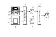
図において、ひな形顔画像生成部1は人間の顔(検出対象)を含む画像11を複数入力すると、複数の画像11から両目の位置を基準にして、顔領域12だけを切り出すとともに、その顔領域12のサイズを正規化して、同一サイズの顔画像14を出力する部分画像切出し部13と、部分画像切出し部13から出力された複数の顔画像14の画素毎の平均値を計算して平均顔画像を求め、その平均顔画像をひな形顔画像16として出力するひな形顔画像計算部15とから構成されている。
なお、ひな形顔画像計算部15は、複数の顔画像14の画素毎の平均値を計算して平均顔画像を求める代わりに、複数の顔画像14の主成分を分析して第一固有ベクトルを計算することにより代表的な顔画像を求め、その代表的な顔画像をひな形顔画像16として出力してもよい。
FIG. 1 is a block diagram showing a detection target identifying apparatus according to
In the figure, when the template face
Note that the template face
前処理部2はひな形顔画像生成部1により生成されたひな形顔画像16に二次元直交関数フィルタを適用し、その適用結果を出力する前処理手段を構成している。メモリ3は前処理部2から出力されたひな形顔画像16に対する二次元直交関数フィルタの適用結果を記憶する記憶手段を構成している。
The preprocessing
画像入力部4には例えばカメラなどの映像機器が接続され、その映像機器により撮像された画像(検出対象である顔が含まれている可能性がある画像)を入力する。あるいは、コンピュータに保存されている画像を入力する。
領域切出し部5は画像入力部4により入力された画像21の中から、識別対象の領域22を順次切り出して出力する(図5を参照)。なお、領域切出し部5は領域切出し手段を構成している。
For example, a video device such as a camera is connected to the image input unit 4 and an image captured by the video device (an image that may include a face to be detected) is input. Alternatively, an image stored in the computer is input.
The
フィルタリング部6は領域切出し部5が識別対象の領域22を切り出す毎に、その領域22の画像に二次元直交関数フィルタを適用する。なお、フィルタリング部6はフィルタリング手段を構成している。
判定部7はフィルタリング部6の適用結果とメモリ3に格納されている適用結果を照合することにより、領域切出し部5により切り出された領域22の画像が顔を表しているか否かを判定する。なお、判定部7は判定手段を構成している。
The filtering unit 6 applies a two-dimensional orthogonal function filter to the image of the
The determination unit 7 compares the application result of the filtering unit 6 with the application result stored in the
情報出力部8は判定部7の判定結果が領域切出し部5により切り出された領域22の画像が顔を表している旨を示す場合には、その領域22の位置を特定する領域情報を出力するとともに、その領域22の画像をメモリ9に出力する。メモリ9は情報出力部8から出力された領域の画像を保存する。なお、情報出力部8及びメモリ9から対象画像保存手段が構成されている。
When the determination result of the determination unit 7 indicates that the image of the
図3は二次元直交関数フィルタの一例を示す説明図、図4はひな形顔画像16に対する二次元直交関数フィルタの適用結果を示す説明図、図5は領域切出し部5により切り出された領域の画像に対する二次元直交関数フィルタの適用結果を示す説明図である。
図6はこの発明の実施の形態1による検出対象識別装置の処理内容を示すフローチャートである。
3 is an explanatory diagram illustrating an example of a two-dimensional orthogonal function filter, FIG. 4 is an explanatory diagram illustrating a result of applying the two-dimensional orthogonal function filter to the
FIG. 6 is a flowchart showing the processing contents of the detection target identification device according to
次に動作について説明する。
検出対象識別装置は、入力画像に含まれている人間の顔を検出するに先立って、人間の一般的な顔を表しているひな形顔画像16を生成する(ステップST1)。
即ち、ひな形顔画像生成部1の部分画像切出し部13は、予め用意されている人間の顔を含む画像11を複数入力すると、複数の画像11から両目の位置を基準にして、顔領域12だけを切り出す処理を実施する。
Next, the operation will be described.
Prior to detecting a human face included in the input image, the detection target identification device generates a
That is, when a plurality of
ここでは、顔領域12を切り出すに際して、両目の位置を基準にしているが、鼻が領域の中心に位置するように切り出してもよい。
この際、両目の位置や鼻の位置を特定する必要があるが、人間の目や鼻の形は、多少の相違があっても大きな特徴は同じであるので、これらの位置は容易に特定することができる。例えば、略楕円の画像が水平方向に2つ並んでいれば、その画像が目であると認識する。また、略二等辺三角形の画像が両目の下に存在していれば、その画像が鼻であると認識する。
Here, when the
At this time, it is necessary to specify the position of both eyes and the position of the nose, but the human eyes and the shape of the nose have the same major characteristics even if there are some differences, so these positions can be easily identified. be able to. For example, if two substantially elliptical images are arranged in the horizontal direction, the image is recognized as an eye. In addition, if an image of an approximately isosceles triangle exists under both eyes, the image is recognized as a nose.
ひな形顔画像生成部1の部分画像切出し部13は、複数の画像11から顔領域12だけを切り出すと、その顔領域12のサイズを正規化して、同一サイズの顔画像14を出力する。
即ち、複数の画像11から切り出した顔領域12のサイズが相互に異なる場合、各顔領域12を拡大、あるいは、縮小することにより、全ての顔領域12のサイズが後述する二次元直交関数フィルタを構成する各フィルタのサイズと同じになるように、各顔領域12のサイズを正規化する。
When only the
That is, when the sizes of the
ひな形顔画像生成部1のひな形顔画像計算部15は、部分画像切出し部13から複数の顔画像14を受けると、複数の顔画像14の画素毎の平均値を計算して平均顔画像を求め、その平均顔画像をひな形顔画像16として出力する。
なお、ひな形顔画像計算部15は、複数の顔画像14の画素毎の平均値を計算して平均顔画像を求める代わりに、複数の顔画像14の主成分を分析して第一固有ベクトルを計算することにより代表的な顔画像を求め、その代表的な顔画像をひな形顔画像16として出力してもよい。
When receiving a plurality of
Note that the template face
前処理部2は、ひな形顔画像生成部1からひな形顔画像16を受けると、ひな形顔画像16に二次元直交関数フィルタを適用し、その適用結果を出力する(ステップST2)。
具体的には、図3に示すような二次元Walsh−Hadamard変換フィルタなどの二次元直交関数フィルタを使用するが(図3の例では、8×8ブロックサイズの二次元Walsh−Hadamard変換フィルタを示しているが、ブロックサイズは8×8に限るものではなく、例えば、16×16のブロックサイズでもよい)、二次元Walsh−Hadamard変換フィルタを構成する各フィルタの白い部分は“1”の係数を有し、黒い部分は“−1”の係数を有している。
Upon receiving the
Specifically, a two-dimensional orthogonal function filter such as a two-dimensional Walsh-Hadamard transform filter as shown in FIG. 3 is used (in the example of FIG. 3, a two-dimensional Walsh-Hadamard transform filter having an 8 × 8 block size is used. Although the block size is not limited to 8 × 8, for example, a block size of 16 × 16 may be used. The white part of each filter constituting the two-dimensional Walsh-Hadamard transform filter is a coefficient of “1”. The black part has a coefficient of “−1”.
前処理部2は、二次元直交関数フィルタの各ファイルを順番にひな形顔画像16に適用する。即ち、各ファイル毎に、ひな形顔画像16の画素値と、ひな形顔画像16の画素に対応する部分のフィルタ係数(“1”or“−1”)を乗算し、全画素の乗算結果を加算することにより、フィルタの応答値を取得する。図4では、各フィルタの下に表示している数値がフィルタの応答値である。
前処理部2は、各フィルタの応答値を取得すると、その応答値の絶対値が大きい順に(応答値の絶対値が大きいフィルタは、一般的な人間の顔の特徴を明瞭に表現している)、数個のフィルタ17を選択し(図4の例では、9個のフィルタを選択している)、そのフィルタ17の応答値を要素とするひな形特徴量ベクトル18を構築する。
The
When the
前処理部2により構築されたひな形特徴量ベクトル18は、ひな形顔画像16に対する二次元直交関数フィルタの適用結果としてメモリ3に格納される。
なお、画像に二次元直交関数フィルタを適用して特徴量ベクトルを構築する手法については、例えば、R.C.Gonzalez,R.E.Woods著の“Digital Image Processing”等の一般的な画像処理の教科書に記載されている。
The
For a method of constructing a feature vector by applying a two-dimensional orthogonal function filter to an image, see, for example, R.A. C. Gonzalez, R.A. E. It is described in textbooks for general image processing such as “Digital Image Processing” by Woods.
検出対象識別装置は、上記のようにして、ひな形顔画像16に対する二次元直交関数フィルタの適用結果として、ひな形特徴量ベクトル18をメモリ3に格納すると、実際に入力画像に顔が含まれているか否かを識別する処理を開始する。
検出対象識別装置の画像入力部4は、検出対象である顔が含まれている可能性がある画像21、即ち、映像機器により撮像された画像、あるいは、コンピュータに保存されている画像を入力する。
As described above, the detection target identification apparatus stores the
The image input unit 4 of the detection target identification device inputs an
領域切出し部5は、画像入力部4が画像21を入力すると(ステップST3)、その入力画像21の中から、図5に示すように、識別対象の領域22を順次切り出す切出し処理を実施する(ステップST4)。
ただし、識別対象の領域22のサイズは、二次元Walsh−Hadamard変換フィルタを構成する各フィルタのサイズと一致している。
When the image input unit 4 inputs the image 21 (step ST3), the
However, the size of the
フィルタリング部6は、領域切出し部5が識別対象の領域22を切り出す毎に、その領域22の画像に二次元Walsh−Hadamard変換フィルタを適用する(ステップST5)。
即ち、フィルタリング部6は、二次元Walsh−Hadamard変換フィルタを構成する各フィルタのうち、前処理部2により選択された数個のフィルタ17を順番に、その領域22の画像に適用する。
具体的には、数個のフィルタ17毎に、その領域22の画像の画素値と、その画像の画素に対応する部分のフィルタ係数(“1”or“−1”)を乗算し、全画素の乗算結果を加算することにより、フィルタの応答値を取得する。
フィルタリング部6は、数個のフィルタ17の応答値を取得すると、数個のフィルタ17の応答値を要素とする特徴量ベクトル23を構築する。
The filtering unit 6 applies a two-dimensional Walsh-Hadamard transform filter to the image of the
That is, the filtering unit 6 sequentially applies
Specifically, every
When obtaining the response values of
判定部7は、フィルタリング部6が特徴量ベクトル23を構築すると、その特徴量ベクトル23(識別対象の領域22の画像に対する二次元直交関数フィルタの適用結果)とメモリ3に格納されているひな形特徴量ベクトル18(ひな形顔画像16に対する二次元直交関数フィルタの適用結果)を照合することにより、その適用結果の一致度を算出する(ステップST6)。
即ち、判定部7は、例えば、特徴量ベクトル23とひな形特徴量ベクトル18とのベクトル内積値を適用結果の一致度として計算する。
判定部7は、その適用結果の一致度が所定の閾値を上回る場合(ステップST7)、その領域22の画像が顔を表している旨を示す判定結果を出力する(ステップST8)。
一方、その適用結果の一致度が所定の閾値を上回らない場合(ステップST7)、その領域22の画像が顔を表していない旨を示す判定結果を出力する(ステップST10)。
When the filtering unit 6 constructs the
That is, the determination unit 7 calculates, for example, the vector inner product value of the
When the degree of coincidence of the application result exceeds a predetermined threshold (step ST7), the determination unit 7 outputs a determination result indicating that the image in the
On the other hand, when the degree of coincidence of the application result does not exceed a predetermined threshold (step ST7), a determination result indicating that the image of the
情報出力部8は、判定部7の判定結果が領域切出し部5により切り出された領域22の画像が顔を表している旨を示す場合には、その領域22の位置を特定する領域情報を出力する。また、その領域22の画像をメモリ9に格納する(ステップST9)。
領域切出し部5は、入力画像21の全てをスキャンするまで、その入力画像21の中から、識別対象の領域22の切出し処理を繰り返し、その領域22の画像に対して、フィルタリング部6及び判定部7が上述した処理を行う(ステップST11)。
When the determination result of the determination unit 7 indicates that the image of the
The
以上で明らかなように、この実施の形態1によれば、領域切出し部5が解析対象の領域22を切り出す毎に、その領域22の画像にWalsh−Hadamard変換フィルタを適用するフィルタリング部6と、検出対象を表しているひな形顔画像16に対する二次元Walsh−Hadamard変換フィルタの適用結果を、ひな形画像に対するWalsh−Hadamard変換フィルタの応答値の絶対値が大きい順に複数個のフィルタを選択し、選択されたフィルタ情報を記憶するとともに、フィルタ適用結果の応答値を要素とするひな形特徴量ベクトルとして記憶する格納するメモリ3とを設け、そのフィルタリング部6の適用結果を、メモリ3で記憶されているフィルタ情報に基づいてフィルタ応答値を選択して要素として構成される識別対象特徴量ベクトルとメモリ3にひな形特徴量ベクトルとして記憶されている適用結果を照合して、その領域切出し部5により切り出された領域22の画像が顔を表しているか否かを判定するように構成したので、大量の画像を学習することなく、ひな形顔画像16に対する二次元直交関数フィルタの適用処理を実施するだけで検出対象の識別処理を開始することができるようになり、その結果、速やかに検出対象である顔の識別処理を開始することができる効果を奏する。
また、識別対象の領域22の画像とひな形顔画像16との距離を演算することなく、フィルタリング部6の適用結果とメモリ3に格納されている適用結果を照合するだけで、その領域22の画像が顔を表しているか否かを判定することができるので、短時間で検出対象の有無を識別することができる効果を奏する。
As is apparent from the above, according to the first embodiment, each time the
Further, without calculating the distance between the image of the
また、この実施の形態1によれば、ひな形顔画像16に二次元Walsh−Hadamard変換フィルタを適用し、その適用結果を用いてWalsh−Hadamard変換フィルタの応答値の絶対値が大きい順に複数個のフィルタを選択し、選択されたフィルタ情報と、フィルタ適用結果の応答値をひな形特徴量ベクトル18としてメモリ3に格納する前処理部2を設けるように構成したので、大量の画像を学習することなく、検出対象である顔の識別処理を開始することができる効果を奏する。
Further, according to the first embodiment, a two-dimensional Walsh-Hadamard transform filter is applied to the
なお、この実施の形態1では、二次元直交関数フィルタとして、二次元Walsh−Hadamard変換フィルタを使用するものについて示したが、二次元Walsh−Hadamard変換フィルタを使用する場合、各画素における演算は、その画素値に“1”あるいは“−1”を乗算するだけであるので、このような演算が組み込まれた画像センサを利用すれば、このフィルタの適用処理をさらに高速化することができる。
このような画像センサの例として、例えば、雑誌「Nature, “Artificial Retinas − Fast, Versatile Image Processors”」(Vol.372, No.6502, pp197−198, 1994)や、特開平8−242265号公報に記載されている人工網膜LSIを用いることができる。
In the first embodiment, a two-dimensional Walsh-Hadamard transform filter is used as a two-dimensional orthogonal function filter. However, when a two-dimensional Walsh-Hadamard transform filter is used, the calculation for each pixel is as follows. Since only the pixel value is multiplied by “1” or “−1”, the application processing of this filter can be further accelerated by using an image sensor in which such a calculation is incorporated.
Examples of such image sensors include, for example, the magazine “Nature,“ Artificial Retinas—Fast, Versatile Image Processors ”” (Vol. 372, No. 6502, pp 197-198, 1994) and Japanese Patent Laid-Open No. 8-242265. Can be used.
実施の形態2.
上記実施の形態1では、人間の顔を含む画像11をひな形顔画像生成部1の部分画像切出し部13に入力することにより、ひな形顔画像16を生成し、入力画像21から人間の顔を検出するものについて示したが、人間の顔以外を検出対象とするようにしてもよい。
例えば、検出対象が犬の顔であれば、犬の顔を含む画像11をひな形顔画像生成部1の部分画像切出し部13に入力することにより、犬の顔に係るひな形顔画像16を生成すればよい。
In the first embodiment, the
For example, if the detection target is a dog's face, an
実施の形態3.
上記実施の形態1では、二次元直交関数フィルタとして、二次元Walsh−Hadamard変換フィルタを使用するものについて示したが、これに限るものではなく、例えば、高速フーリエ変換フィルタ、離散コサイン変換フィルタ、あるいは、ウェーブレット変換フィルタを使用し、これらのフィルタを画像に適用するようにしてもよい。この場合も、上記実施の形態1と同様の効果を奏することができる。
In the first embodiment, the two-dimensional orthogonal function filter that uses a two-dimensional Walsh-Hadamard transform filter has been described. However, the present invention is not limited to this. For example, a fast Fourier transform filter, a discrete cosine transform filter, or Alternatively, wavelet transform filters may be used and these filters may be applied to the image. Also in this case, the same effect as in the first embodiment can be obtained.
実施の形態4.
上記実施の形態1では、8×8ブロックサイズの二次元Walsh−Hadamard変換フィルタを使用するものについて示したが(図3を参照)、フィルタリング部6がフィルタサイズの変更が可能な二次元Walsh−Hadamard変換フィルタを領域切出し部5により切り出された領域22の画像に適用するようにしてもよい。
Embodiment 4 FIG.
In
具体的には、フィルタリング部6は、領域切出し部5が解析対象の領域22を切り出すと、最初の段階では、図7に示すように、二次元Walsh−Hadamard変換フィルタのフィルタサイズが最小サイズである一次適用フィルタ31(図7の例では、4×4ブロックサイズの二次元Walsh−Hadamard変換フィルタが最小サイズであるが、これに限るものではなく、例えば、6×6ブロックサイズの二次元Walsh−Hadamard変換フィルタが最小サイズであってもよい)を領域22の画像に適用する。
そして、判定部7は、一次適用フィルタ31の適用結果とメモリ3に格納されている適用結果を照合して、その領域22の画像が顔を表しているか否かを判別する。
Specifically, when the
Then, the determination unit 7 collates the application result of the primary application filter 31 with the application result stored in the
フィルタリング部6は、判定部7の判定結果が顔を表している旨を示す場合には、更に高解像度の識別処理を実施して、その領域22の画像が顔を表していることの確度を高めるため、二次元Walsh−Hadamard変換フィルタのフィルタサイズを拡大して、二次適用フィルタ32(図7の例では、6×6ブロックサイズの二次元Walsh−Hadamard変換フィルタを使用しているが、これに限るものではなく、例えば、8×8ブロックサイズの二次元Walsh−Hadamard変換フィルタを使用してもよい)を領域22の画像に適用する。
フィルタリング部6は、判定部7の判定結果が顔を表していない旨を示す場合には、その領域22の画像が顔を表していないことは明らかであり、更に高解像度の識別処理を実施しても意味がないため、その領域22の画像に対する二次元Walsh−Hadamard変換フィルタの適用処理を中止する。したがって、領域切出し部5は、入力画像21の全てをスキャンしていなければ、次の領域22の切出し処理を実施する。
判定部7は、フィルタリング部6が二次適用フィルタ32を領域22の画像に適用すると、二次適用フィルタ32の適用結果とメモリ3に格納されている適用結果を照合して、その領域22の画像が顔を表しているか否かを判別する。
When the determination result of the determination unit 7 indicates that the filtering unit 6 indicates a face, the filtering unit 6 further performs a higher resolution identification process to determine the accuracy of the image of the
When the determination result of the determination unit 7 indicates that the face does not represent a face, the filtering unit 6 clearly indicates that the image of the
When the filtering unit 6 applies the
フィルタリング部6は、二次適用フィルタ32を使用しても、判定部7の判定結果が顔を表している旨を示す場合には、更に高解像度の識別処理を実施して、その領域22の画像が顔を表していることの確度を高めるため、二次元Walsh−Hadamard変換フィルタのフィルタサイズを拡大して、三次適用フィルタ33(図7の例では、8×8ブロックサイズの二次元Walsh−Hadamard変換フィルタを使用しているが、これに限るものではなく、例えば、10×10ブロックサイズの二次元Walsh−Hadamard変換フィルタを使用してもよい)を領域22の画像に適用する。
フィルタリング部6は、判定部7の判定結果が顔を表していない旨を示す場合には、その領域22の画像が顔を表していないことは明らかであり、更に高解像度の識別処理を実施しても意味がないため、その領域22の画像に対する二次元Walsh−Hadamard変換フィルタの適用処理を中止する。したがって、領域切出し部5は、入力画像21の全てをスキャンしていなければ、次の領域22の切出し処理を実施する。
判定部7は、フィルタリング部6が三次適用フィルタ33を領域22の画像に適用すると、三次適用フィルタ33の適用結果とメモリ3に格納されている適用結果を照合して、その領域22の画像が顔を表しているか否かを判別する。図7の例では、この判別結果が当該領域22の画像に関する最終識別結果となる。
When the filtering unit 6 uses the
When the determination result of the determination unit 7 indicates that the face does not represent a face, the filtering unit 6 clearly indicates that the image of the
When the filtering unit 6 applies the tertiary application filter 33 to the image in the
以上で明らかなように、この実施の形態4によれば、最初の段階では一次適用フィルタ31を領域22の画像に適用し、その適用結果から判定部7により検出対象である顔を表している旨を示す判定結果が得られると、その二次元Walsh−Hadamard変換フィルタのフィルタサイズを順次拡大して、その二次元Walsh−Hadamard変換フィルタを領域22の画像に適用するように構成したので、その領域22の画像が顔を表していないことが一次適用フィルタ31や二次適用フィルタ32を適用する低解像度の段階で判明すると、高解像度の三次適用フィルタ33を適用するまえに、その領域22の画像に対する二次元Walsh−Hadamard変換フィルタの適用処理を中止することができる結果、顔を表していない領域に対する識別処理の高速化を図ることができる効果を奏する。
As apparent from the above, according to the fourth embodiment, the primary application filter 31 is applied to the image in the
1 ひな形顔画像生成部、2 前処理部(前処理手段)、3 メモリ(記憶手段)、4 画像入力部、5 領域切出し部(領域切出し手段)、6 フィルタリング部(フィルタリング手段)、7 判定部(判定手段)、8 情報出力部(対象画像保存手段)、9 メモリ(対象画像保存手段)、11 画像、12 顔領域、13 部分画像切出し部、14 顔画像、15 ひな形顔画像計算部、16 ひな形顔画像、17 応答値の絶対値が大きいフィルタ、18 ひな形特徴量ベクトル、21 入力画像、22 領域、23 特徴量ベクトル。
DESCRIPTION OF
Claims (5)
Priority Applications (1)
| Application Number | Priority Date | Filing Date | Title |
|---|---|---|---|
| JP2004010732A JP4439927B2 (en) | 2004-01-19 | 2004-01-19 | Detection target identification device |
Applications Claiming Priority (1)
| Application Number | Priority Date | Filing Date | Title |
|---|---|---|---|
| JP2004010732A JP4439927B2 (en) | 2004-01-19 | 2004-01-19 | Detection target identification device |
Publications (2)
| Publication Number | Publication Date |
|---|---|
| JP2005202860A JP2005202860A (en) | 2005-07-28 |
| JP4439927B2 true JP4439927B2 (en) | 2010-03-24 |
Family
ID=34823370
Family Applications (1)
| Application Number | Title | Priority Date | Filing Date |
|---|---|---|---|
| JP2004010732A Expired - Fee Related JP4439927B2 (en) | 2004-01-19 | 2004-01-19 | Detection target identification device |
Country Status (1)
| Country | Link |
|---|---|
| JP (1) | JP4439927B2 (en) |
Families Citing this family (1)
| Publication number | Priority date | Publication date | Assignee | Title |
|---|---|---|---|---|
| JP4840978B2 (en) * | 2006-05-11 | 2011-12-21 | キヤノン株式会社 | IMAGING DEVICE, ITS CONTROL METHOD, PROGRAM, AND STORAGE MEDIUM |
Family Cites Families (7)
| Publication number | Priority date | Publication date | Assignee | Title |
|---|---|---|---|---|
| JP2875263B2 (en) * | 1988-09-21 | 1999-03-31 | ヤマハ発動機株式会社 | Image processing method and apparatus |
| JP2542487B2 (en) * | 1994-02-25 | 1996-10-09 | 工業技術院長 | Optical information processing system |
| JP3720412B2 (en) * | 1995-05-01 | 2005-11-30 | キヤノン株式会社 | Information processing method and apparatus |
| JP3675984B2 (en) * | 1996-09-12 | 2005-07-27 | 株式会社ルネサステクノロジ | Light receiving element circuit and light receiving element circuit array |
| KR100941209B1 (en) * | 2001-08-23 | 2010-02-10 | 소니 주식회사 | Robot device, face recognition method and face recognition device |
| JP2003271933A (en) * | 2002-03-18 | 2003-09-26 | Sony Corp | Face detection device, face detection method, and robot device |
| JP4164737B2 (en) * | 2002-05-24 | 2008-10-15 | ソニー株式会社 | Object recognition apparatus and method, and robot apparatus |
-
2004
- 2004-01-19 JP JP2004010732A patent/JP4439927B2/en not_active Expired - Fee Related
Also Published As
| Publication number | Publication date |
|---|---|
| JP2005202860A (en) | 2005-07-28 |
Similar Documents
| Publication | Publication Date | Title |
|---|---|---|
| CN110163899B (en) | Image matching method and image matching device | |
| JP5047005B2 (en) | Image processing method, pattern detection method, pattern recognition method, and image processing apparatus | |
| JP5517504B2 (en) | Image processing apparatus, image processing method, and program | |
| JP4877374B2 (en) | Image processing apparatus and program | |
| JP5671928B2 (en) | Learning device, learning method, identification device, identification method, and program | |
| JP2018028899A5 (en) | ||
| CN102422325B (en) | Pattern recognition apparatus and method therefor configured to recognize object and another lower-order object | |
| US8107725B2 (en) | Image processor and image processing method | |
| TW200529093A (en) | Face image detection method, face image detection system, and face image detection program | |
| JP7210890B2 (en) | Behavior recognition device, behavior recognition method, its program, and computer-readable recording medium recording the program | |
| JP5936561B2 (en) | Object classification based on appearance and context in images | |
| JP7225978B2 (en) | Active learning method and active learning device | |
| CN114782892A (en) | Illegal behavior target detection method, device, equipment and storage medium | |
| JP6410450B2 (en) | Object identification device, object identification method, and program | |
| JPWO2012046426A1 (en) | Object detection apparatus, object detection method, and object detection program | |
| CN114863431A (en) | Text detection method, device and equipment | |
| JP2010176504A (en) | Image processor, image processing method, and program | |
| Jijina et al. | Detection of recoloring and copy-move forgery in digital images | |
| JP5335554B2 (en) | Image processing apparatus and image processing method | |
| KR20230060439A (en) | Method and system for detecting recaptured image method thereof | |
| JP4439927B2 (en) | Detection target identification device | |
| JP5791361B2 (en) | PATTERN IDENTIFICATION DEVICE, PATTERN IDENTIFICATION METHOD, AND PROGRAM | |
| JP2019106089A (en) | INFORMATION PROCESSING APPARATUS, INFORMATION PROCESSING METHOD, AND COMPUTER PROGRAM | |
| CN119942253A (en) | Dimensionality reduction methods | |
| JP4099981B2 (en) | Image recognition system, image recognition method, and image recognition program |
Legal Events
| Date | Code | Title | Description |
|---|---|---|---|
| A621 | Written request for application examination |
Free format text: JAPANESE INTERMEDIATE CODE: A621 Effective date: 20061124 |
|
| RD04 | Notification of resignation of power of attorney |
Free format text: JAPANESE INTERMEDIATE CODE: A7424 Effective date: 20071016 |
|
| RD04 | Notification of resignation of power of attorney |
Free format text: JAPANESE INTERMEDIATE CODE: A7424 Effective date: 20080714 |
|
| A977 | Report on retrieval |
Free format text: JAPANESE INTERMEDIATE CODE: A971007 Effective date: 20090918 |
|
| A131 | Notification of reasons for refusal |
Free format text: JAPANESE INTERMEDIATE CODE: A131 Effective date: 20090929 |
|
| A521 | Request for written amendment filed |
Free format text: JAPANESE INTERMEDIATE CODE: A523 Effective date: 20091126 |
|
| TRDD | Decision of grant or rejection written | ||
| A01 | Written decision to grant a patent or to grant a registration (utility model) |
Free format text: JAPANESE INTERMEDIATE CODE: A01 Effective date: 20091222 |
|
| A01 | Written decision to grant a patent or to grant a registration (utility model) |
Free format text: JAPANESE INTERMEDIATE CODE: A01 |
|
| A61 | First payment of annual fees (during grant procedure) |
Free format text: JAPANESE INTERMEDIATE CODE: A61 Effective date: 20100106 |
|
| FPAY | Renewal fee payment (event date is renewal date of database) |
Free format text: PAYMENT UNTIL: 20130115 Year of fee payment: 3 |
|
| R150 | Certificate of patent or registration of utility model |
Ref document number: 4439927 Country of ref document: JP Free format text: JAPANESE INTERMEDIATE CODE: R150 Free format text: JAPANESE INTERMEDIATE CODE: R150 |
|
| FPAY | Renewal fee payment (event date is renewal date of database) |
Free format text: PAYMENT UNTIL: 20130115 Year of fee payment: 3 |
|
| R250 | Receipt of annual fees |
Free format text: JAPANESE INTERMEDIATE CODE: R250 |
|
| R250 | Receipt of annual fees |
Free format text: JAPANESE INTERMEDIATE CODE: R250 |
|
| R250 | Receipt of annual fees |
Free format text: JAPANESE INTERMEDIATE CODE: R250 |
|
| R250 | Receipt of annual fees |
Free format text: JAPANESE INTERMEDIATE CODE: R250 |
|
| LAPS | Cancellation because of no payment of annual fees |