JP4457510B2 - Abnormality detector for exhaust gas recirculation system - Google Patents
Abnormality detector for exhaust gas recirculation system Download PDFInfo
- Publication number
- JP4457510B2 JP4457510B2 JP2001062917A JP2001062917A JP4457510B2 JP 4457510 B2 JP4457510 B2 JP 4457510B2 JP 2001062917 A JP2001062917 A JP 2001062917A JP 2001062917 A JP2001062917 A JP 2001062917A JP 4457510 B2 JP4457510 B2 JP 4457510B2
- Authority
- JP
- Japan
- Prior art keywords
- amount
- exhaust gas
- intake
- gas recirculation
- opening
- Prior art date
- Legal status (The legal status is an assumption and is not a legal conclusion. Google has not performed a legal analysis and makes no representation as to the accuracy of the status listed.)
- Expired - Fee Related
Links
Images


Classifications
-
- F—MECHANICAL ENGINEERING; LIGHTING; HEATING; WEAPONS; BLASTING
- F02—COMBUSTION ENGINES; HOT-GAS OR COMBUSTION-PRODUCT ENGINE PLANTS
- F02D—CONTROLLING COMBUSTION ENGINES
- F02D41/00—Electrical control of supply of combustible mixture or its constituents
- F02D41/0025—Controlling engines characterised by use of non-liquid fuels, pluralities of fuels, or non-fuel substances added to the combustible mixtures
- F02D41/0047—Controlling exhaust gas recirculation [EGR]
- F02D41/005—Controlling exhaust gas recirculation [EGR] according to engine operating conditions
- F02D41/0052—Feedback control of engine parameters, e.g. for control of air/fuel ratio or intake air amount
-
- F—MECHANICAL ENGINEERING; LIGHTING; HEATING; WEAPONS; BLASTING
- F02—COMBUSTION ENGINES; HOT-GAS OR COMBUSTION-PRODUCT ENGINE PLANTS
- F02D—CONTROLLING COMBUSTION ENGINES
- F02D35/00—Controlling engines, dependent on conditions exterior or interior to engines, not otherwise provided for
- F02D35/0007—Controlling engines, dependent on conditions exterior or interior to engines, not otherwise provided for using electrical feedback
-
- F—MECHANICAL ENGINEERING; LIGHTING; HEATING; WEAPONS; BLASTING
- F02—COMBUSTION ENGINES; HOT-GAS OR COMBUSTION-PRODUCT ENGINE PLANTS
- F02M—SUPPLYING COMBUSTION ENGINES IN GENERAL WITH COMBUSTIBLE MIXTURES OR CONSTITUENTS THEREOF
- F02M26/00—Engine-pertinent apparatus for adding exhaust gases to combustion-air, main fuel or fuel-air mixture, e.g. by exhaust gas recirculation [EGR] systems
- F02M26/49—Detecting, diagnosing or indicating an abnormal function of the EGR system
-
- F—MECHANICAL ENGINEERING; LIGHTING; HEATING; WEAPONS; BLASTING
- F02—COMBUSTION ENGINES; HOT-GAS OR COMBUSTION-PRODUCT ENGINE PLANTS
- F02D—CONTROLLING COMBUSTION ENGINES
- F02D41/00—Electrical control of supply of combustible mixture or its constituents
- F02D41/0002—Controlling intake air
- F02D2041/0017—Controlling intake air by simultaneous control of throttle and exhaust gas recirculation
-
- F—MECHANICAL ENGINEERING; LIGHTING; HEATING; WEAPONS; BLASTING
- F02—COMBUSTION ENGINES; HOT-GAS OR COMBUSTION-PRODUCT ENGINE PLANTS
- F02D—CONTROLLING COMBUSTION ENGINES
- F02D41/00—Electrical control of supply of combustible mixture or its constituents
- F02D41/02—Circuit arrangements for generating control signals
- F02D41/18—Circuit arrangements for generating control signals by measuring intake air flow
- F02D41/187—Circuit arrangements for generating control signals by measuring intake air flow using a hot wire flow sensor
-
- F—MECHANICAL ENGINEERING; LIGHTING; HEATING; WEAPONS; BLASTING
- F02—COMBUSTION ENGINES; HOT-GAS OR COMBUSTION-PRODUCT ENGINE PLANTS
- F02M—SUPPLYING COMBUSTION ENGINES IN GENERAL WITH COMBUSTIBLE MIXTURES OR CONSTITUENTS THEREOF
- F02M26/00—Engine-pertinent apparatus for adding exhaust gases to combustion-air, main fuel or fuel-air mixture, e.g. by exhaust gas recirculation [EGR] systems
- F02M26/13—Arrangement or layout of EGR passages, e.g. in relation to specific engine parts or for incorporation of accessories
- F02M26/17—Arrangement or layout of EGR passages, e.g. in relation to specific engine parts or for incorporation of accessories in relation to the intake system
- F02M26/21—Arrangement or layout of EGR passages, e.g. in relation to specific engine parts or for incorporation of accessories in relation to the intake system with EGR valves located at or near the connection to the intake system
-
- F—MECHANICAL ENGINEERING; LIGHTING; HEATING; WEAPONS; BLASTING
- F02—COMBUSTION ENGINES; HOT-GAS OR COMBUSTION-PRODUCT ENGINE PLANTS
- F02M—SUPPLYING COMBUSTION ENGINES IN GENERAL WITH COMBUSTIBLE MIXTURES OR CONSTITUENTS THEREOF
- F02M26/00—Engine-pertinent apparatus for adding exhaust gases to combustion-air, main fuel or fuel-air mixture, e.g. by exhaust gas recirculation [EGR] systems
- F02M26/45—Sensors specially adapted for EGR systems
- F02M26/48—EGR valve position sensors
-
- Y—GENERAL TAGGING OF NEW TECHNOLOGICAL DEVELOPMENTS; GENERAL TAGGING OF CROSS-SECTIONAL TECHNOLOGIES SPANNING OVER SEVERAL SECTIONS OF THE IPC; TECHNICAL SUBJECTS COVERED BY FORMER USPC CROSS-REFERENCE ART COLLECTIONS [XRACs] AND DIGESTS
- Y02—TECHNOLOGIES OR APPLICATIONS FOR MITIGATION OR ADAPTATION AGAINST CLIMATE CHANGE
- Y02T—CLIMATE CHANGE MITIGATION TECHNOLOGIES RELATED TO TRANSPORTATION
- Y02T10/00—Road transport of goods or passengers
- Y02T10/10—Internal combustion engine [ICE] based vehicles
- Y02T10/40—Engine management systems
Landscapes
- Engineering & Computer Science (AREA)
- Chemical & Material Sciences (AREA)
- Combustion & Propulsion (AREA)
- Mechanical Engineering (AREA)
- General Engineering & Computer Science (AREA)
- Exhaust-Gas Circulating Devices (AREA)
- Combined Controls Of Internal Combustion Engines (AREA)
- Electrical Control Of Air Or Fuel Supplied To Internal-Combustion Engine (AREA)
- Control Of Throttle Valves Provided In The Intake System Or In The Exhaust System (AREA)
- Output Control And Ontrol Of Special Type Engine (AREA)
Description
【0001】
【発明の属する技術分野】
本発明は、内燃機関に設けられた排気還流装置の異常の有無を検出する異常検出装置に関するものである。
【0002】
【従来の技術】
従来より、車載用エンジン等の内燃機関として、排気エミッションの改善を意図して、排気ガスの一部を吸気通路に還流させる排気還流(EGR)装置を備えたものが知られている。このEGR装置は、内燃機関の排気通路及び吸気通路間を連通するEGR通路と、同通路に設けられたEGR弁とを備えている。そして、EGR弁の開度を調整することにより、排気通路からEGR通路を通じて吸気通路へ還流される排気ガスの量(EGR量)が調整される。こうしたEGR装置によって排気ガスの一部が吸気通路に戻されると、同排気ガスにより燃焼温度が下がって燃焼室内での窒素酸化物(NOx)の生成が抑制され、排気エミッションが改善されるようになる。
【0003】
このようなEGR装置に何らかの異常、例えば、EGR弁の動きが鈍くなったり、EGR弁が固着して作動しなくなったり、異物や排気ガス中の炭化物等によりEGR通路が詰まったりすると、EGR量がそのときの機関運転状態に適した値から外れる場合がある。この場合、燃焼状態が悪化したり、NOxが増加したりする。そこで、EGR装置の異常を検出する装置が種々提案されている。
【0004】
例えば、特開平8−86248号公報では、アイドル回転制御実行条件及び自己診断開始条件がともに満たされているとき、実EGR開度が目標EGR開度と一致するようにEGR開度を制御し、機関回転速度が目標回転速度と一致するようにISCデューティ比を制御する。機関回転速度が目標回転速度に一致したとき、ISCデューティ比の現在値と目標値との偏差を求め、この値を用いてEGR目標開度修正テーブルから修正値を求める。そして、この修正値がしきい値以上である状態が所定時間続いた場合、異常であると判定している。
【0005】
【発明が解決しようとする課題】
ところが、前記公報記載の異常検出装置では、アイドル領域においてEGR開度の制御を行っているときに、異常検出のための各種処理を行っている。このため、EGR装置に何らかの異常が起きた場合、その異常を検出することができる機関運転領域がアイドル領域に限られてしまう。従って、アイドル領域でEGRを行わない内燃機関では、異常を検出できないことになる。このように、適用の対象となるEGR装置が、アイドル領域でもEGRを行うものに制限されるという問題がある。
【0006】
本発明はこのような実情に鑑みてなされたものであって、その目的は、排気還流が行われる領域であれば、アイドル領域に限らずどの領域であっても排気還流装置の異常を検出することができ、内燃機関のアイドル領域で排気還流を行わない排気還流装置にも適用することのできる異常検出装置を提供することにある。
【0007】
【課題を解決するための手段】
以下、上記目的を達成するための手段及びその作用効果について記載する。
請求項1記載の発明では、内燃機関の排気通路と吸気通路の吸気絞り弁下流とを連通する排気還流通路に設けられ、前記排気通路から前記排気還流通路を通じて前記吸気通路に還流される排気ガスの還流量を調整する排気還流弁と、前記吸気通路を流れる吸入空気の量を検出する吸入空気量検出手段と、前記吸入空気量検出手段による吸入空気量が、前記内燃機関の運転状態に応じた目標吸入空気量に一致するように、前記排気還流弁の開度をフィードバック制御する制御手段とを備える排気還流装置に用いられる異常検出装置において、前記フィードバック制御のフィードバック項が、通常取り得る範囲よりも広く設定された所定範囲から外れているとき、前記吸気絞り弁の開度を変更する絞り開度変更手段と、前記絞り開度変更手段により前記吸気絞り弁の開度が所定量変更されても、前記フィードバック項の変化量が所定値以下である場合に、前記排気還流装置が異常であると判定する異常判定手段とを備えている。
【0008】
上記の構成によれば、排気還流装置では、吸気通路において吸気絞り弁下流に生ずる吸気圧力(負圧)が排気還流通路に作用することにより、排気通路を流れる排気ガスの一部が排気還流通路を通じて吸気通路に還流される。この還流される排気ガスが燃焼室に流入することにより、燃焼温度が下がって燃焼室内での窒素酸化物の生成が抑制される。この際、吸気通路に戻される排気ガスの還流量は排気還流弁によって調整される。また、排気還流装置では、吸気通路を流れる吸入空気の量が吸入空気量検出手段によって検出される。そして、検出された吸入空気量が、内燃機関の運転状態に応じた目標吸入空気量に一致するように、排気還流弁の開度が制御手段によりフィードバック制御される。
【0009】
このフィードバック制御では、実際の吸入空気量が目標吸入空気量よりも少なくなると、排気還流弁の開度が閉じ側に変更される。この変更により、吸気通路への排気ガスの還流量が減少し、それにともない吸入空気量が増加する。これとは逆に、実際の吸入空気量が目標吸入空気量よりも多くなると、排気還流弁の開度が開き側に変更される。この変更により排気ガスの還流量が増加し、吸入空気量が減少する。
【0010】
また、前記フィードバック制御では、例えば吸気絞り弁がそのときの機関運転状態とは関係なく意図的に閉じられる等して、実際の吸入空気量が目標吸入空気量よりも少なくなると、その偏差を吸収すべくフィードバック項が減少して排気還流弁の開度が閉じ側に変更される。これとは逆に、例えば吸気絞り弁が意図的に開かれる等して、実際の吸入空気量が目標吸入空気量よりも多くなると、その偏差を吸収すべくフィードバック項が増加して排気還流弁の開度が開き側に変更されるはずである。
【0011】
ところで、前記フィードバック項が、通常取り得る範囲よりも広く設定された所定範囲から外れているとき、すなわち、通常取り得ない値になっているとき、排気還流装置に異常が発生している可能性が高いことから、吸気絞り弁の開度が絞り開度変更手段により強制的に変更される。この変更にともない、吸入空気量と、そのときの機関運転状態に応じた目標吸入空気量との偏差が大きくなる。この際、仮に排気還流弁の開度が正常に制御されていれば、前述したように前記偏差を吸収すべくフィードバック項が変化する。そして、吸気絞り弁の開度がある程度の量変更されると、フィードバック項の変化量は所定値を越えるはずである。そこで、異常判定手段では、絞り開度変更手段により吸気絞り弁の開度が所定量変更されても、フィードバック項の変化量が所定値以下である(フィードバック項が変化しない場合も含む)と、排気還流装置が異常であると判定される。
【0012】
このように、排気還流装置に異常が起きた場合、その異常を検出することが可能である。しかも、排気還流弁の開度が制御手段によってフィードバック制御されている領域であれば、アイドル領域に限らず、どの領域であっても排気還流装置の異常を検出することが可能である。このため、異常検出装置を、アイドル領域で排気還流を行わない排気還流装置にも適用できるようになる。
【0013】
請求項2記載の発明では、請求項1記載の発明において、前記絞り開度変更手段は、前記フィードバック項が前記所定範囲の上限値以上である場合には、前記吸気絞り弁の開度を閉じ側に変更し、下限値以下である場合には、同開度を開き側に変更するものであり、前記異常判定手段は、前記絞り開度変更手段により前記吸気絞り弁の開度が第1変更判定値以上に変更されても、前記フィードバック項の変化量が所定値以下である場合に、前記排気還流装置が異常であると判定し、前記吸気絞り弁の開度が第2変更判定値以下に変更されても、前記フィードバック項の変化量が所定値以下である場合に、前記排気還流装置が異常であると判定するものであるとする。
【0014】
上記の構成によれば、絞り開度変更手段では、フィードバック項と、所定範囲の上・下限値との関係において、吸気絞り弁の開度が以下のように変更される。フィードバック項が上限値以上である場合には、吸気絞り弁の開度が閉じ側に変更される。この際、仮に排気還流弁の開度が正常に制御されていれば、吸気絞り弁の強制的な閉弁により吸入空気量が減少し、フィードバック項が小さくなるはずである。そこで、異常判定手段では、閉じ側への所定量の開度変更により、吸気絞り弁の開度が第1変更判定値以上になっているにもかかわらず、フィードバック項の変化量が所定値以下である場合、排気還流装置が異常であると判定される。
【0015】
前記とは逆に、フィードバック項が下限値以下である場合には、吸気絞り弁の開度が開き側に変更される。この際、仮に排気還流弁の開度が正常に制御されていれば、吸気絞り弁の強制的な開弁により吸入空気量が増加し、フィードバック項が大きくなるはずである。そこで、異常判定手段では、開き側への所定量の開度変更により、吸気絞り弁の開度が第2変更判定値以下になっているにもかかわらず、フィードバック項の変化量が所定値以下である場合、排気還流装置が異常であると判定される。
【0016】
請求項3記載の発明では、請求項2記載の発明において、前記吸気絞り弁は前記吸気通路内に回動可能に支持されており、さらに、前記絞り開度変更手段により前記吸気絞り弁の開度が開き側に変更される場合の時間当りの変更量は、閉じ側に変更される場合の時間当りの変更量よりも多く設定されているとする。
【0017】
上記の構成によれば、吸気通路においては、吸気絞り弁の回動角度に応じて、その吸気絞り弁の開度が変化する。そして、この開度に応じて、吸気通路において吸気絞り弁よりも下流の吸気圧力が変化するとともに、同吸気通路を流れる吸入空気量が変化する。ここで、吸気絞り弁が全閉と全開の中間の開度にあるとして、その状態から開度が閉じ側に変更される場合と、開き側に変更される場合とでは、その変更量に応じた吸入空気量の変化量が異なる。具体的には、前者の変化量の方が後者の変化量よりも多い。従って、仮に、絞り開度変更手段において、吸気絞り弁の開度を変更する側に関係なく、時間当りの変更量を同一にすると、その変更量によっては、吸気絞り弁の開度を閉じ側に変更した場合に、吸入空気量が急激に変化するおそれがある。
【0018】
これに対し、請求項3記載の発明では、吸気絞り弁の開度が開き側に変更される場合の時間当りの変更量が、閉じ側に変更される場合の時間当りの変更量よりも多い。このため、吸気絞り弁の開度の変更にともなう吸入空気量の変化量を、閉じ側と開き側とで同程度にすることが可能である。こうすると、吸気絞り弁の開度が閉じ又は開きのどちら側に変更されても吸入空気量の変化が同程度となるため、燃焼状態や出力トルクの変化も同程度となる。さらに、吸気絞り弁の開度が閉じ側に変更される場合を基準とし、この場合の吸気絞り弁の開度の時間当りの変更量が少なくされれば、吸入空気量の急激な変化が小さくなり、出力トルクの急激な変化が抑制される。
【0019】
請求項4記載の発明では、請求項2記載の発明において、前記吸気絞り弁は前記吸気通路内に回動可能に支持されており、前記異常判定手段は、前記第1変更判定値及び前記第2変更判定値の少なくとも一方を、前記内燃機関の回転速度及び燃料噴射量に応じて異ならせるものであるとする。
【0020】
上記の構成によれば、第1変更判定値及び第2変更判定値の少なくとも一方が、内燃機関のそのときの回転速度と燃料噴射量とに応じて変更される。従って、上記請求項3記載の発明において説明した、吸気絞り弁の開度に対する吸入空気量の特性が、たとえ内燃機関の回転速度と燃料噴射量とによって決定される機関運転領域毎に異なっていても、最適な変更判定値を設定して排気還流装置の異常を検出することが可能である。
【0021】
請求項5記載の発明では、請求項4記載の発明において、前記異常判定手段は、前記吸気絞り弁の開度を閉じ側に変更する場合について、前記内燃機関の回転速度及び燃料噴射量に基づいて決定される変更判定値を予め記憶した第1記憶手段と、そのときの内燃機関の回転速度及び燃料噴射量に対応する変更判定値を前記第1記憶手段から読出し、これを前記第1変更判定値として設定する第1判定値設定手段とを備え、前記吸気絞り弁の開度を開き側に変更する場合について、前記内燃機関の回転速度及び燃料噴射量に基づいて決定される変更判定値を予め記憶した第2記憶手段と、そのときの内燃機関の回転速度及び燃料噴射量に対応する変更判定値を前記第2記憶手段から読出し、これを前記第2変更判定値として設定する第2判定値設定手段とを備えるものであるとする。
【0022】
上記の構成によれば、異常判定手段による異常判定に際しては、記憶手段が参照されて、内燃機関のそのときの回転速度と燃料噴射量とに対応する変更判定値が読出され、第1変更判定値又は第2変更判定値として設定される。各変更判定値の設定に際し参照される記憶手段は、吸気絞り弁の開度を閉じ側に変更する場合と、開き側に変更する場合とで切替えられる。
【0023】
詳しくは、吸気絞り弁の開度が閉じ側に変更される場合、第1判定値設定手段では、そのときの内燃機関の回転速度及び燃料噴射量に対応する変化判定値が第1記憶手段から読出され、これが第1変更判定値として設定される。また、吸気絞り弁の開度が開き側に変更される場合、第2判定値設定手段では、そのときの内燃機関の回転速度及び燃料噴射量に対応する変化判定値が第2記憶手段から読出され、これが第2変更判定値として設定される。
【0024】
従って、吸気絞り弁の開度に対する吸入空気量の特性が、内燃機関の回転速度と燃料噴射量とによって決定される機関運転領域毎に異なっていても、前記のように記憶手段を切替えることにより、吸気絞り弁の開度が閉じ側に変更される場合にも、開き側に変更される場合にも、変更判定値を最適な値に設定することが可能となる。
【0025】
請求項6記載の発明では、請求項1〜5のいずれか1つに記載の発明において、前記異常判定手段は、前記絞り開度変更手段により吸気絞り弁の開度が開き側に前記所定量変更されても、前記フィードバック項の変化量が所定値以下である場合に、前記排気還流弁の開弁状態での不具合により前記排気還流装置が異常であると判定するものであるとする。
【0026】
上記の構成によれば、吸気絞り弁の開度が開き側に所定量変更されても、フィードバック項が変化しない又はほとんど変化しないのは、排気ガスの還流量が過剰なまま減少しない場合である。このような現象が起るのは、排気還流弁が開弁したまま不具合を起こしている場合に限られる。そこで、異常判定手段では、絞り開度変更手段により吸気絞り弁の開度が開き側に所定量変更されても、フィードバック項の変化量が所定値以下である場合、排気還流弁の開弁状態での不具合により排気還流装置が異常であると判定される。このように、単に異常の有無が判定されるのみならず、その原因が特定されるため、対処がしやすくなる。
請求項7に記載の発明は、内燃機関の排気通路と吸気通路の吸気絞り弁下流とを連通する排気還流通路に設けられ、前記排気通路から前記排気還流通路を通じて前記吸気通路に還流される排気ガスの還流量を調整する排気還流弁と、前記吸気通路を流れる吸入空気の量を検出する吸入空気量検出手段と、前記吸入空気量検出手段による吸入空気量が、前記内燃機関の運転状態に応じた目標吸入空気量に一致するように、前記排気還流弁の開度をフィードバック制御する制御手段とを備える排気還流装置に用いられる異常検出装置において、前記フィードバック制御のフィードバック項が、通常取り得る範囲よりも広く設定された所定範囲から外れているとき、前記吸気絞り弁の開度を変更する絞り開度変更手段と、前記絞り開度変更手段により前記吸気絞り弁の開度が所定量変更されても、前記フィードバック項が前記絞り開度変更手段での前記所定範囲から外れている場合に、前記排気還流装置が異常であると判定する異常判定手段とを備えている。
【0027】
【発明の実施の形態】
以下、本発明に係る排気還流装置の異常検出装置を車両用ディーゼルエンジンに適用した一実施形態を、図面に従って説明する。
【0028】
車両には、図1に示すように、内燃機関としてディーゼルエンジン11が搭載されている。ディーゼルエンジン11は、シリンダヘッド12と、複数の気筒(シリンダ)13を有するシリンダブロック14とを備えている。各シリンダ13内にはピストン15が往復動可能に収容されている。各ピストン15はコネクティングロッド16を介し、ディーゼルエンジン11の出力軸であるクランク軸17に連結されている。各ピストン15の往復運動は、コネクティングロッド16によって回転運動に変換された後、クランク軸17に伝達される。
【0029】
ディーゼルエンジン11には、シリンダ13毎に燃焼室18が設けられている。各燃焼室18には、吸気通路19及び排気通路20が接続されている。シリンダヘッド12には、シリンダ13毎に吸気弁21及び排気弁22が設けられている。これらの吸・排気弁21,22は、クランク軸17の回転に連動して往復動することにより、吸・排気通路19,20と燃焼室18との各接続部分を開閉する。
【0030】
吸気通路19には、エアクリーナ23、吸気絞り弁であるスロットル弁24等が配置されている。ディーゼルエンジン11の吸気行程において、排気弁22が閉じられ、吸気弁21が開かれた状態でピストン15が下降すると、シリンダ13内の気圧が外気より低い値(負圧)になり、同エンジン11の外部の空気は、吸気通路19の各部を順に通過して燃焼室18に吸い込まれる。
【0031】
スロットル弁24は、吸気通路19内に回動可能に支持されており、同スロットル弁24に連結されたステップモータ等のアクチュエータ25により駆動される。吸気通路19を流れる空気の量である吸入空気量は、スロットル弁24の回動角度に対応したスロットル開度に応じて変化する。スロットル開度は、スロットル弁24が全開状態のときに最小(0%)となり、閉じられるほど増加し、全閉状態のときに最大(100%)となる。
【0032】
シリンダヘッド12には、シリンダ13毎の燃焼室18に燃料を噴射する燃料噴射弁27が取付けられている。各燃料噴射弁27は電磁弁(図示略)を備えており、この電磁弁により、燃料噴射弁27から各燃焼室18への燃料噴射が制御される。シリンダ13毎の燃料噴射弁27は、共通の畜圧配管であるコモンレール28に接続されており、電磁弁が開いている間、コモンレール28内の燃料が、燃料噴射弁27から対応する燃焼室18に噴射される。コモンレール28には、燃料噴射圧に相当する比較的高い圧力が蓄積されている。この畜圧を実現するために、コモンレール28は、供給配管29を介してサプライポンプ30に接続されている。サプライポンプ30は、燃料タンク31から燃料を吸入するとともに、ディーゼルエンジン11の回転に同期する図示しないカムによってプランジャを往復動させ、燃料を所定圧に高めてコモンレール28に供給する。
【0033】
そして、吸気通路19を通ってシリンダ13内に導入され、かつピストン15により圧縮された高温かつ高圧の吸入空気に、燃料噴射弁27から燃料が噴射される。噴射された燃料は自己着火して燃焼する。このときに生じた燃焼ガスによりピストン15が往復動され、クランク軸17が回転されて、ディーゼルエンジン11の駆動力(出力トルク)が得られる。燃焼ガスは、排気弁22の開弁にともない排気通路20に排出される。
【0034】
ディーゼルエンジン11には、排気通路20を流れる排気ガスの一部を、吸気通路19に還流させる排気還流(以下「EGR」という)装置32が設けられている。EGR装置32は、還流にともない吸入空気に混合された排気ガス(EGRガス)により、混合気中の不活性ガスの割合を増やして燃焼最高温度を下げ、大気汚染物質である窒素酸化物(NOx)の発生を低減させるためのものである。
【0035】
EGR装置32は、EGR通路33及びEGR弁34を備えている。EGR通路33は、排気通路20と、吸気通路19においてスロットル弁24よりも下流側の箇所とをつないでいる。EGR弁34はEGR通路33の途中、例えば、EGR通路33の吸気通路19との接続箇所にリフト可能に取付けられている。EGR通路33を流れるEGRガスの流量は、EGR弁34の開き具合であるEGR開度に応じて変化する。EGR開度は、EGR弁34のリフト量に応じて変化する。また、EGR開度は、前述したスロットル開度とは逆に、EGR弁34が全閉状態のときに最小(0%)となり、開かれるほど増加し、全開状態のときに最大(100%)となる。
【0036】
車両には、ディーゼルエンジン11の運転状態を検出するために各種センサが設けられている。吸気通路19において、エアクリーナ23の下流近傍には、吸入空気量を検出するエアフロメータ35が取付けられている。スロットル弁24には、その回動角度に基づきスロットル開度を検出するスロットルポジションセンサ36が取付けられている。吸気通路19において、スロットル弁24の下流側には、吸入空気の圧力である吸気圧力を検出する吸気圧力センサ37が取付けられている。EGR弁34には、EGR開度を検出するEGR開度センサ38が取付けられている。
【0037】
シリンダブロック14には、ウォータジャケット14aを流れる冷却水の温度である冷却水温を検出する水温センサ39が取付けられている。クランク軸17の近傍には、そのクランク軸17が所定角度回転する毎にパルス信号を出力するクランクポジションセンサ40が配置されている。このパルス信号は、クランク軸17の時間当りの回転数であるエンジン回転速度の検出に用いられる。さらに、アクセルペダル26の近傍には、運転者による同ペダル26の踏込み量であるアクセル開度を検出するアクセル開度センサ41が配置されている。
【0038】
前記各種センサ35〜41の検出値に基づきディーゼルエンジン11の各部を制御するために、車両には電子制御装置(Electronic Control Unit: ECU)42が設けられている。ECU42はマイクロコンピュータを中心として構成されており、中央処理装置(CPU)が、読出し専用メモリ(ROM)に記憶されている制御プログラム、初期データ、制御マップ等に従って演算処理を行い、その演算結果に基づいて各種制御を実行する。CPUによる演算結果は、ランダムアクセスメモリ(RAM)において一時的に記憶される。
【0039】
前記各種制御としては、燃料噴射制御、スロットル制御、EGR制御、EGR装置32の異常検出制御等が挙げられる。例えば、燃料噴射制御では、燃料噴射弁27から噴射される燃料の量及び噴射時期を決定する。燃料噴射量の決定に際しては、例えば、所定の制御マップを参照して、エンジン回転速度及びアクセル開度に対応した基本燃料噴射量(基本燃料噴射時間)を算出する。冷却水温、吸入空気量等に基づき基本燃料噴射時間を補正し、最終的な燃料噴射時間を決定する。また、燃料噴射時期の決定に際しては、例えば、所定の制御マップを参照し、エンジン回転速度及びアクセル開度に対応した基本燃料噴射時期を算出する。冷却水温、吸入空気量等に基づき基本燃料噴射時期を補正して、最終的な燃料噴射時期を決定する。このように、燃料噴射時間及び燃料噴射時期を決定すると、クランクポジションセンサ40の出力信号が燃料噴射開始時期と一致した時点で、燃料噴射弁27への通電を開始する。この開始時点から前記燃料噴射時間が経過した時点で通電を停止する。
【0040】
スロットル制御では、例えばエンジン回転速度及び燃料噴射量に対応した目標スロットル開度を算出する。スロットルポジションセンサ36によって検出される実際のスロットル開度が前記目標スロットル開度に一致するように、アクチュエータ25を駆動制御する。
【0041】
EGR制御では、例えばエンジン回転速度、冷却水温、アクセル開度等に基づき、EGR制御の実行条件が成立しているか否かを判定する。EGR制御実行条件としては、例えば冷却水温が所定値以上であること、ディーゼルエンジン11が始動時から所定時間以上連続して運転されていること、アクセル開度の変化量が正値であること等が挙げられる。そして、このEGR制御実行条件が成立していない場合には、EGR弁34を全閉状態に保持する。一方、前記実行条件が成立している場合には、所定の制御マップを参照して、エンジン回転速度及び燃料噴射量に対応するEGR弁34の目標開度を算出し、この値に基づきEGR弁34を駆動制御する。
【0042】
さらに、EGR制御では、吸入空気量をパラメータとしてEGR開度をフィードバック制御する。この制御は、エアフロメータ35によって検出される実際の吸入空気量を、ディーゼルエンジン11の運転状態に応じた目標吸入空気量に一致させるためのものである。同制御では、前記エンジン回転速度及び燃料噴射量により求めた目標開度をベース項とし、これにフィードバック(F/B)項を加算することにより最終的な目標EGR開度を求め、その値に基づきEGR弁34を制御する。F/B項は、EGR弁34、エアフロメータ35等のばらつきが吸入空気量に及ぼす影響や、EGR通路33での堆積物による詰りが吸入空気量に及ぼす影響を吸収するためのものであり、通常、−20%〜+20%の範囲内の値を取る。
【0043】
このフィードバック制御によると、実際の吸入空気量が目標吸入空気量よりも少なくなると、EGR弁34を所定量閉弁させる。この場合、EGR通路33から吸気通路19内へ流入するEGRガスの量が減少し、それに応じてシリンダ13に吸入されるEGRガスの量が減少することになる。その結果、シリンダ13に吸入される新気の量は、EGRガスが減少した分だけ増加する。
【0044】
一方、実際の吸入空気量が目標吸入空気量よりも多くなると、EGR弁34を所定量開弁させる。この場合、EGR通路33から吸気通路19へ流入するEGRガスの量が増加し、それに応じてシリンダ13に吸入されるEGRガスの量が増加する。その結果、シリンダ13内に吸入される新気の量は、EGRガスが増加した分だけ減少することになる。
【0045】
なお、EGRガス量を増加させる必要がある場合に、既にEGR弁34が全開状態にあると、スロットル弁24を所定開度閉弁させるべくアクチュエータ25を制御する。この場合、吸気通路19においてスロットル弁24より下流では、吸気圧力の負圧度合が大きくなるため、EGR通路33から吸気通路19に吸入されるEGRガスの量が増加することになる。
【0046】
次に、EGR装置32の異常検出制御について説明する。ECU42はこの制御に際し、図2及び図3のフローチャートに示す「異常検出ルーチン」を実行する。このルーチンは所定時間毎に繰り返し実行される。異常検出ルーチンでは、前記フィードバック制御におけるF/B項の挙動を利用して異常を検出するようにしている。その挙動とは、例えばスロットル弁24がそのときのエンジン運転状態とは関係なく意図的に閉じられる等して、実際の吸入空気量が目標吸入空気量よりも少なくなると、その偏差を吸収すべくF/B項が減少する。これとは逆に、例えばスロットル弁24が意図的に開かれる等して、実際の吸入空気量が目標吸入空気量よりも多くなると、その偏差を吸収すべくF/B項が増加することである。
【0047】
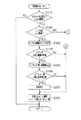
ECU42は、まずステップS110において、スロットル弁24の制御が正常に行われているか否かを判定するとともに、ディーゼルエンジン11の運転状態がEGR制御を行う領域に属しているか否かを判定する。後者の判定は、前述したEGR制御の実行条件の成立の有無に基づき行う。これらの判定条件の一方又は両方が満たされていないと異常検出ルーチンを終了し、両方とも満たされていると、ステップS120,S130へ移行する。
【0048】
これらステップS120,S130の処理は、F/B項が所定範囲から外れているかどうかを判定するためのものである。所定範囲は、F/B項が通常取り得る範囲よりも広く(例えば−50%〜+50%)設定されており、ROMに予め記憶されている。この所定範囲の上限値及び下限値は、EGR装置32の各部や環境条件のばらつきを考慮しても、F/B項が取るはずのない値である。
【0049】
前記ステップS120では、F/B項が所定範囲の上限値以上であるか否かを判定し、ステップS130では、F/B項が所定範囲の下限値以下であるか否かを判定する。前記ステップS120,S130の判定条件がともに満たされていないと、ステップS140において、オフセット項、F/B大継続カウンタ及びF/B小継続カウンタをそれぞれ初期化する。
【0050】
ここで、オフセット項は、EGR装置32の異常検出に際し、EGR弁34の開度を強制的に変更するために用いられる。詳しくは、オフセット項は、前述したスロットル制御において、最終的な目標スロットル開度の算出に際し、エンジン回転速度及び燃料噴射量に対応した目標スロットル開度をベース項とし、これに加算されるものである。ステップS140では、このオフセット項を「0%」に設定する。また、F/B大継続カウンタは、F/B項が上限値以上である状態の継続時間を計測するためのものである。F/B小継続カウンタは、F/B項が下限値以下である状態の継続時間を計測するためのものである。ステップS140では、これらの継続カウンタをいずれも「0」に設定する。
【0051】
前記ステップS140の処理を行った後、ステップS150において、最終的な目標スロットル開度を算出し、異常検出ルーチンを終了する。目標スロットル開度の算出に際しては、前述したように前記ベース項にオフセット項を加算する。こうして求めた目標スロットル開度は、別のルーチンにおいて、スロットル制御の目標値として用いられる。すなわち、スロットルポジションセンサ36によって検出される実際のスロットル開度が前記目標スロットル開度に一致するように、アクチュエータ25が駆動制御される。
【0052】
一方、前記ステップS120の判定条件が満たされていると、ステップS160においてF/B大継続カウンタをインクリメントする。次に、ステップS170において、前記F/B大継続カウンタの値が第1継続判定値以上であるか否かを判定する。第1継続判定値は、例えば10秒に相当する値である。同ステップS170の判定条件が満たされていないと、前述したステップS150へ移行する。
【0053】
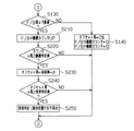
これに対し、F/B項が上限値以上である状態がある時間(ここでは10秒間)継続していると、EGR装置32に異常が発生している可能性が高い。このことから、ステップS170の判定条件が満たされていると、ステップS180において、前回のオフセット項に所定値αを加算する。そして、その加算結果を新たなオフセット項として設定する。前記ステップS180での加算処理は、オフセット項を増加させることにより、ステップS150での目標スロットル開度を大きくして、スロットル開度を閉じ側に変更するための処理である。
【0054】
ここで、スロットル開度の時間当りの変更量は、異常検出ルーチンの制御周期と所定値αによって決まる。所定値αが大きいほど、スロットル開度を閉じ側に変更する際の時間当りの変更量が多くなる。また、スロットル弁24が全閉と全開の中間の開度にあるとして、その状態からスロットル開度を閉じ側に変更する場合と、開き側に変更する場合とでは、その変更量に応じた吸入空気量の変化量が異なる。具体的には、図4に示すように、同じ量a1,a2だけスロットル開度を変更しても、閉じ側に変更した場合の吸入空気量の変化量b1の方が、開き側に変更した場合の吸入空気量の変化量b2よりも多い。従って、時間当りの変更量を、仮に、スロットル開度の閉じ側についても開き側についても同一又は同程度に設定すると、その設定した変更量によっては、閉じ側では吸入空気量が急激に変化し、これにともない内燃機関の出力トルクが急激に変化するおそれがある。
【0055】
ここでは、前述した図4のスロットル開度に対する吸入空気量の特性を考慮し、閉じ側に変更するための所定値αを小さな値、例えば「1%」に設定する。この設定により、スロットル開度を閉じ側に変更する場合に、吸入空気量が急激に変化するのを抑制している。
【0056】
次に、図2のステップS190において、前記ステップS180でのオフセット項が第1変更判定値以上であるか否かを判定する。第1変更判定値としては、例えばROMに記憶された第1制御マップ(図示略)から読出したものを用いる。この第1制御マップには、エンジン回転速度及び燃料噴射量に基づいて決定される変更判定値が規定されている。そして、そのときのエンジン回転速度及び燃料噴射量に対応した変更判定値を第1制御マップから読出し、これをステップS190での第1変更判定値として設定する。
【0057】
ステップS190の判定条件が満たされていないと、前記ステップS150へ移行し、満たされていると、ステップS200の処理を経てステップS150へ移行する。ステップS200では、EGR装置32が異常であると判定する。すなわち、ステップS180の処理によりオフセット項が増大するが、このオフセット項が第1変更判定値よりも小さい限り、異常と判定しない。増大によりオフセット項が第1変更判定値以上になったところで、異常と判定する。
【0058】
このように、本実施形態では、F/B項が所定範囲の上限値以上である場合、EGR制御が正常に行われていない可能性が高いと判断し、オフセット項を増大させることにより、エンジン運転状態に関係なくスロットル開度を閉じ側に変更している。この変更にともない、実際の吸入空気量と、そのときのエンジン運転状態に応じた目標吸入空気量との偏差が小さくなる。この際、仮にEGR開度が正常に制御されていれば、前述したようにその偏差を吸入すべくF/B項が変化(減少)する。そして、スロットル開度が閉じ側へある程度の量変更されると、F/B項が上限値よりも小さな値になって所定範囲内に入るはずである。それにもかかわらずF/B項が上限値以上であり続けるのは、EGR装置32に異常が起っているものと考えられる。そこで、前記増加によりオフセット項が第1変更判定値以上となっても、F/B項が所定範囲の上限値以上である場合に、EGR装置32が異常であると判定している。
【0059】
一方、前記ステップS130の判定条件が満たされていると、ステップS210においてF/B小継続カウンタをインクリメントする。次に、ステップS220において、F/B小継続カウンタの値が第2継続判定値以上であるか否かを判定する。第2継続判定値は、前記第1継続判定値と同じであってもよいし、異なっていてもよい。ステップS220の判定条件が満たされていないと、前述したステップS150へ移行する。
【0060】
これに対し、ステップS220の判定条件が満たされていると、ステップS230において、前回のオフセット項から所定値βを減算する。そして、その減算結果を新たなオフセット項として設定する。前記ステップS230での減算処理は、オフセット項を減少させることにより、ステップS150での目標スロットル開度を小さくして、スロットル開度を開き側に変更するためのものである。
【0061】
ここで、所定値βが大きくなるほど、スロットル開度を開き側に変更する場合の時間当りの変更量が多くなる。また、スロットル開度と吸入空気量との間には、前述した図4に示す関係が見られる。このスロットル開度に対する吸入空気量の特性を考慮し、開き側に変更した場合の吸入空気量の変化量が、閉じ側に変更した場合の吸入空気量の変化量と同程度となるように、所定値βが前記所定値αよりも大きな値、例えば「5%」に設定されている。
【0062】
次に、ステップS240において、前記ステップS230でのオフセット項が第2変更判定値以下であるか否かを判定する。第2変更判定値としては、例えばROMに記憶された第2制御マップ(図示略)から読出したものを用いる。この第2制御マップには、エンジン回転速度及び燃料噴射量に基づいて決定される変更判定値が規定されている。エンジン回転速度及び燃料噴射量に対する変更判定値の傾向は、第1制御マップと第2制御マップとで異なっている。そして、そのときのエンジン回転速度及び燃料噴射量に対応した変更判定値を第2制御マップから読出し、これをステップS240での第2変更判定値として設定する。
【0063】
ステップS240の判定条件が満たされていないと、前記ステップS150へ移行し、満たされていると、ステップS250の処理を経てステップS150へ移行する。ステップS250では、EGR弁34の開弁状態での不具合、例えば固着、摺動不良等が原因で、EGR装置32に異常が起っていると判定する。すなわち、ステップS230の処理によりオフセット項が減少するが、このオフセット項が第2変更判定値より大きい限り、異常と判定しない。そして、減少によりオフセット項が第2変更判定値以下となったところで異常と判定する。
【0064】
このように、F/B項が所定範囲の下限値以下である場合、EGR開度が正常に制御されていない可能性が高いと判断し、オフセット項を減少させることにより、エンジン運転状態に関係なくスロットル開度を開き側に変更している。この変更にともない実際の吸入空気量と、そのときのエンジン運転状態に応じた目標吸入空気量との偏差が大きくなる。この際、仮にEGR開度が正常に制御されていれば、前述したように前記偏差を吸入すべくF/B項が変化(増加)する。そして、スロットル開度が開き側へある程度変更されると、F/B項が下限値よりも大きな値になって所定範囲内に入るはずである。それにもかかわらずF/B項が下限値以下であり続けるのは、EGR装置32に異常が起っているものと考えられる。そこで、前記減少によりオフセット項が第2変更判定値以下になっても、F/B項が所定範囲の下限値以下である場合に、EGR装置32が異常であると判定している。
【0065】
また、EGR装置32の異常の原因を、EGR弁34の開弁状態での不具合と特定するのは、以下の理由による。スロットル開度が開き側に所定量変更されてもF/B項が所定範囲の下限値以下であり続けるのは、EGR量が過剰なまま減少しない場合である。このような現象が起るのは、EGR弁34が開弁したまま、固着、摺動不良等の不具合を起こしている場合に限られるからである。
【0066】
以上詳述した本実施形態によれば、以下の効果が得られる。
(1)F/B項が、通常取り得る範囲よりも広く設定された所定範囲から外れていると、EGR制御が正常に行われていない可能性が高いと判断し、スロットル開度を変更している。そして、スロットル開度を所定量変更しても、F/B項の変化量が所定値以下である場合に、EGR装置32が異常であると判定するようにしている。このため、EGR装置32に何らかの異常が起きてもその異常を検出し、早期に対処することが可能となる。
【0067】
(2)EGR開度のフィードバック制御は、EGR領域の全域を対象して行われる。このため、EGR領域であれば、その領域にかかわらず異常を検出することができる。従って、従来技術とは異なり、異常検出装置を、アイドル領域でEGRを行わないタイプのEGR装置にも適用可能である。
【0068】
(3)F/B項が所定範囲内に入っている場合には、異常検出のためのEGR開度の強制的な変更を行わないようにしている。このため、EGR装置32が異常である可能性がさほど高くない場合にまでEGR開度の変更が行われるのを防止し、不要な吸入空気量の変化を抑制することができる。
【0069】
(4)異常検出のためのスロットル開度の変更により吸入空気量が変化し、ディーゼルエンジン11での燃焼状態が変化する。その結果、燃焼音が少なからず変化したり、出力トルクが変化してショックが発生したりするおそれがある。これに対しては、異常検出を、例えば車両の走行領域で行うことにより、前記燃焼音の変化やショックを目立たなくすることが可能である。これは、走行中には、スロットル開度の変化にともなうポンピングロスの発生トルクに及ぼす影響が小さいこと、走行にともない生ずる騒音が燃焼音を打消すように作用すること等による。この点において、本実施形態は、アイドル領域でしか異常を検出できない従来技術に比べ優れている。
【0070】
(5)所定値αを小さな値(例えば1%)に設定することにより、オフセット項を徐々に増加させるようにしている。このため、スロットル開度を閉じ側に変更する場合には、その変更量に対する吸入空気量の変化量が比較的大きいが、前記所定値αの設定により吸入空気量の急激な変化が抑制され、ディーゼルエンジン11での燃焼状態の急激な変化が抑えられる。その結果、出力トルクの急激な変化にともなうショックの発生を小さくし、車両の乗員に対し、ドライバビリティについての違和感を与えないようにすることが可能である。
【0071】
(6)スロットル開度を開き側に変更する場合には、閉じ側に変更する場合よりも同スロットル開度を多く変更するようにしている。すなわち、所定値βを所定値α(例えば1%)よりも大きな値(例えば5%)に設定することにより、スロットル開度を開き側に変更する際のオフセット項の時間当りの変更量を、閉じ側に変更する際のオフセット項の時間当りの変更量よりも多くしている。このため、スロットル開度と吸入空気量との間には図4に示すような関係が見られるが、スロットル開度を開き又は閉じのどちら側に変更する場合であっても、吸入空気量の変化量や、燃焼状態の変化を同程度にすることができる。
【0072】
(7)エンジン回転速度及び燃料噴射量に応じて第1変更判定値及び第2変更判定値を異ならせるようにしている。このため、図4に示す吸入空気量の特性が、たとえエンジン回転速度と燃料噴射量とによって決定される運転領域毎に異なっていても、各変更判定値を最適な値に設定することが可能である。
【0073】
(8)エンジン回転速度及び燃料噴射量に基づいて決定される変更判定値を規定した制御マップを作成しておき、そのときのエンジン回転速度及び燃料噴射量に対応する変更判定値を制御マップから読出し、オフセット項との比較に用いるようにしている。しかも、異なる傾向の変更判定値を規定した2種類の制御マップ(第1制御マップ、第2制御マップ)を作成しておき、スロットル開度を開き側に変更する場合と、閉じ側に変更する場合とで、使用する制御マップを切替えている。このため、スロットル開度に対する吸入空気量の特性が、エンジン回転速度と燃料噴射量とによって決定されるエンジン運転領域毎に異なっていても、前記のように別々の制御マップを参照することにより、スロットル開度が中間の開度から閉じ側に変更される場合にも、開き側に変更される場合にも、変更判定値を最適な値に設定することが可能となる。
【0074】
(9)スロットル開度が開き側に所定量変更されても、F/B項が所定範囲の下限値以下であり続ける場合に、EGR弁34の開弁状態での不具合によりEGR装置32が異常であると判定するようにしている。従って、単に異常の有無を判定するのみならず、その原因までも特定することができ、その後の対処がしやすくなる。
【0075】
(10)F/B項が所定範囲の上限値以上である状態の継続時間をF/B大継続カウンタによって計測するとともに、F/B項が所定範囲の下限値以下である状態の継続時間をF/B小継続カウンタによって計測している。そして、各カウンタの値が所定値を越えている場合(前記状態がある程度の期間にわたって継続している場合)に、スロットル開度を閉じ側又は開き側に変更するようにしている。このため、F/B項が瞬間的に所定範囲から外れる等して、F/B項が所定範囲から外れた状態が比較的短時間で終った場合に、スロットル開度が強制的に変更されるのを防ぐことができる。
【0076】
(11)既設のセンサをEGR装置32の異常検出に利用しているため、異常検出用のセンサを新たに設けなくてもすむ。
(12)スロットル開度変更後のF/B項の変化量に基づき異常の有無を判定するために、同スロットル開度変更前の所定範囲の上限値及び下限値を用いている。このため、別の値を用いる場合に比べ、異常検出ルーチンの制御内容を簡略化することができる。
【0077】
なお、本発明は次に示す別の実施形態に具体化することができる。
・前記実施形態では、第1変更判定値及び第2変更判定値を、それぞれエンジン回転速度及び燃料噴射量に応じて異ならせたが、少なくとも一方の変更判定値を一定の値としてもよい。
【0078】
・本発明の異常検出装置は、EGR装置を装備し、かつ吸入空気量が目標値に一致するようにEGR開度をフィードバック制御するようにした内燃機関であれば、その種類に関係なく適用可能である。
【0079】
・第1及び第2の制御マップに代えて、所定の演算式に従って第1及び第2の変更判定値を算出するようにしてもよい。
・前記実施形態では、スロットル開度を所定量変更しても、F/B項が所定範囲から外れている場合に異常と判定するようにしたが、同変更にもかかわらずF/B項の変化量が所定値以下である(F/B項が変化しない場合も含む)場合に、異常と判定するようにしてもよい。
【0080】
その他、前記各実施形態から把握できる技術的思想について、それらの効果とともに記載する。
(A)請求項1〜6のいずれか1つに記載の排気還流装置の異常検出装置において、前記絞り開度変更手段は、前記フィードバック項が前記所定範囲から外れている状態の継続時間を計測し、その継続時間が所定値以上である場合に、前記吸気絞り弁の開度を変更するものである。
【0081】
上記の構成によれば、瞬間的にフィードバック項が所定範囲から外れる等して、フィードバック項が所定範囲から外れた状態が比較的短時間で終った場合に、スロットル開度が不要に変更されるのを防ぐことができる。
【0082】
(B)請求項1記載の排気還流装置の異常検出装置において、前記異常判定手段は、前記絞り開度変更手段により前記吸気絞り弁の開度が所定量変更されても、前記フィードバック項が前記絞り開度変更手段での前記所定範囲から外れている場合に、前記排気還流装置が異常であると判定するものである。
【0083】
上記の構成によれば、吸気絞り弁の開度変更後のフィードバック項の変化に基づき異常を検出するために、同開度変更前の所定範囲を用いているため、別の値を用いる場合に比べ、異常検出の制御内容を簡略化することが可能である。
【図面の簡単な説明】
【図1】本発明の異常検出装置をディーゼルエンジンに適用した一実施形態についてその構成を示す略図。
【図2】EGR装置の異常を検出する手順を示すフローチャート。
【図3】同じく、EGR装置の異常を検出する手順を示すフローチャート。
【図4】スロットル開度に対する吸入空気量の特性を示すグラフ。
【符号の説明】
11…ディーゼルエンジン、19…吸気通路、20…排気通路、24…スロットル弁、32…EGR装置、33…EGR通路、34…EGR弁、35…エアフロメータ、42…ECU(電子制御装置)。[0001]
BACKGROUND OF THE INVENTION
The present invention relates to an abnormality detection device that detects the presence or absence of an abnormality in an exhaust gas recirculation device provided in an internal combustion engine.
[0002]
[Prior art]
2. Description of the Related Art Conventionally, an internal combustion engine such as an in-vehicle engine is known that includes an exhaust gas recirculation (EGR) device that recirculates a part of exhaust gas to an intake passage in order to improve exhaust emission. The EGR device includes an EGR passage communicating between an exhaust passage and an intake passage of an internal combustion engine, and an EGR valve provided in the passage. Then, by adjusting the opening of the EGR valve, the amount of exhaust gas recirculated from the exhaust passage to the intake passage through the EGR passage (EGR amount) is adjusted. When a part of the exhaust gas is returned to the intake passage by such an EGR device, the exhaust gas lowers the combustion temperature so that the generation of nitrogen oxides (NOx) in the combustion chamber is suppressed and the exhaust emission is improved. Become.
[0003]
If there is any abnormality in such an EGR device, for example, the EGR valve becomes sluggish, the EGR valve becomes stuck and does not operate, or the EGR passage is clogged with foreign matter or carbides in the exhaust gas, the EGR amount becomes There may be cases where the value is not suitable for the engine operating condition at that time. In this case, the combustion state deteriorates or NOx increases. Therefore, various devices for detecting an abnormality of the EGR device have been proposed.
[0004]
For example, in JP-A-8-86248, when both the idle rotation control execution condition and the self-diagnosis start condition are satisfied, the EGR opening is controlled so that the actual EGR opening matches the target EGR opening, The ISC duty ratio is controlled so that the engine rotational speed matches the target rotational speed. When the engine rotational speed matches the target rotational speed, a deviation between the current value of the ISC duty ratio and the target value is determined, and a correction value is determined from the EGR target opening correction table using this value. And when this correction value is more than a threshold value for a predetermined time, it is determined that there is an abnormality.
[0005]
[Problems to be solved by the invention]
However, in the abnormality detection apparatus described in the above publication, various processes for abnormality detection are performed when the EGR opening degree is controlled in the idle region. For this reason, when some abnormality occurs in the EGR device, the engine operation region in which the abnormality can be detected is limited to the idle region. Therefore, an abnormality cannot be detected in an internal combustion engine that does not perform EGR in the idle region. In this way, there is a problem that the EGR device to be applied is limited to those that perform EGR even in the idle region.
[0006]
The present invention has been made in view of such circumstances, and its object is to detect an abnormality in the exhaust gas recirculation device in any region as long as the exhaust gas recirculation is performed, not only in the idle region. An abnormality detection device that can be applied to an exhaust gas recirculation device that does not perform exhaust gas recirculation in an idle region of an internal combustion engine.
[0007]
[Means for Solving the Problems]
In the following, means for achieving the above object and its effects are described.
According to the first aspect of the present invention, the exhaust gas is provided in the exhaust gas recirculation passage that communicates the exhaust passage of the internal combustion engine and the intake throttle valve downstream of the intake passage, and is recirculated from the exhaust passage to the intake passage through the exhaust recirculation passage. The exhaust gas recirculation valve for adjusting the recirculation amount of the exhaust gas, the intake air amount detection means for detecting the amount of intake air flowing through the intake passage, and the intake air amount by the intake air amount detection means depend on the operating state of the internal combustion engine. In an abnormality detection device used in an exhaust gas recirculation device comprising a control means for performing feedback control of the opening degree of the exhaust gas recirculation valve so as to coincide with the target intake air amount, the feedback control feedback term can be normally taken A throttle opening changing means for changing the opening of the intake throttle valve and the throttle opening changing means when it is outside a predetermined range set wider than Wherein also the opening degree of the intake throttle valve is changed a predetermined amount, the amount of change in the feedback term is provided with an abnormality determination means determines that if it is less than the predetermined value, is abnormal the exhaust gas recirculation device.
[0008]
According to the above configuration, in the exhaust gas recirculation device, the intake pressure (negative pressure) generated downstream of the intake throttle valve in the intake passage acts on the exhaust gas recirculation passage, whereby a part of the exhaust gas flowing through the exhaust passage is exhausted. Through the intake passage. When the recirculated exhaust gas flows into the combustion chamber, the combustion temperature is lowered and the production of nitrogen oxides in the combustion chamber is suppressed. At this time, the exhaust gas recirculation amount returned to the intake passage is adjusted by the exhaust gas recirculation valve. In the exhaust gas recirculation device, the amount of intake air flowing through the intake passage is detected by the intake air amount detection means. Then, the opening degree of the exhaust gas recirculation valve is feedback-controlled by the control means so that the detected intake air amount matches the target intake air amount corresponding to the operating state of the internal combustion engine.
[0009]
In this feedback control, when the actual intake air amount becomes smaller than the target intake air amount, the opening degree of the exhaust gas recirculation valve is changed to the closed side. By this change, the recirculation amount of the exhaust gas to the intake passage decreases, and the intake air amount increases accordingly. On the contrary, when the actual intake air amount becomes larger than the target intake air amount, the opening degree of the exhaust gas recirculation valve is changed to the open side. This change increases the recirculation amount of the exhaust gas and decreases the intake air amount.
[0010]
In the feedback control, for example, when the actual intake air amount becomes smaller than the target intake air amount because the intake throttle valve is intentionally closed regardless of the engine operating state at that time, the deviation is absorbed. Accordingly, the feedback term is decreased and the opening degree of the exhaust gas recirculation valve is changed to the closed side. On the contrary, if the actual intake air amount becomes larger than the target intake air amount, for example, when the intake throttle valve is intentionally opened, the feedback term increases to absorb the deviation, and the exhaust gas recirculation valve The opening should be changed to the open side.
[0011]
By the way, when the feedback term deviates from a predetermined range that is set wider than the normally obtainable range, that is, when the feedback term is a value that cannot normally be obtained, there is a possibility that an abnormality has occurred in the exhaust gas recirculation device. Since it is high, the opening degree of the intake throttle valve is forcibly changed by the throttle opening degree changing means. With this change, the deviation between the intake air amount and the target intake air amount according to the engine operating state at that time increases. At this time, if the opening degree of the exhaust gas recirculation valve is normally controlled, the feedback term changes to absorb the deviation as described above. When the opening of the intake throttle valve is changed by a certain amount, the amount of change in the feedback term should exceed a predetermined value. Therefore, in the abnormality determination means, even if the opening degree of the intake throttle valve is changed by a predetermined amount by the throttle opening degree changing means, the change amount of the feedback term is not more than a predetermined value (including the case where the feedback term does not change), It is determined that the exhaust gas recirculation device is abnormal.
[0012]
Thus, when an abnormality occurs in the exhaust gas recirculation device, it is possible to detect the abnormality. Moreover, as long as the opening degree of the exhaust gas recirculation valve is in a region where feedback control is performed by the control means, it is possible to detect an abnormality in the exhaust gas recirculation device not only in the idle region but also in any region. For this reason, the abnormality detection device can be applied to an exhaust gas recirculation device that does not perform exhaust gas recirculation in the idle region.
[0013]
According to a second aspect of the invention, in the first aspect of the invention, the throttle opening changing means closes the opening of the intake throttle valve when the feedback term is equal to or greater than an upper limit value of the predetermined range. When the opening degree is equal to or less than the lower limit value, the opening degree is changed to the opening side, and the abnormality determining means is configured such that the opening degree of the intake throttle valve is first changed by the throttle opening degree changing means. Even if it is changed to a change determination value or more, when the amount of change in the feedback term is equal to or less than a predetermined value, it is determined that the exhaust gas recirculation device is abnormal, and the opening of the intake throttle valve is a second change determination value. Even if it is changed to the following, it is assumed that the exhaust gas recirculation device is determined to be abnormal when the amount of change in the feedback term is equal to or less than a predetermined value.
[0014]
According to the above configuration, the throttle opening degree changing means changes the opening degree of the intake throttle valve as follows in relation to the feedback term and the upper and lower limit values of the predetermined range. If the feedback term is greater than or equal to the upper limit value, the opening of the intake throttle valve is changed to the closed side. At this time, if the opening degree of the exhaust gas recirculation valve is normally controlled, the intake air amount is reduced by forcibly closing the intake throttle valve, and the feedback term should be reduced. Therefore, in the abnormality determination means, the change amount of the feedback term is less than or equal to the predetermined value even though the opening amount of the intake throttle valve is greater than or equal to the first change determination value due to the change of the opening amount by the predetermined amount toward the closing side. If it is, it is determined that the exhaust gas recirculation device is abnormal.
[0015]
Contrary to the above, when the feedback term is equal to or lower than the lower limit value, the opening of the intake throttle valve is changed to the open side. At this time, if the opening degree of the exhaust gas recirculation valve is normally controlled, the intake air amount will increase due to the forced opening of the intake throttle valve, and the feedback term should increase. Therefore, in the abnormality determination means, the change amount of the feedback term is less than or equal to the predetermined value even though the opening amount of the intake throttle valve is less than or equal to the second change determination value due to the change of the opening amount by the predetermined amount to the opening side. If it is, it is determined that the exhaust gas recirculation device is abnormal.
[0016]
According to a third aspect of the present invention, in the second aspect of the present invention, the intake throttle valve is rotatably supported in the intake passage, and the throttle opening changing means opens the intake throttle valve. It is assumed that the amount of change per hour when the degree is changed to the open side is set to be larger than the amount of change per hour when the degree is changed to the closed side.
[0017]
According to the above configuration, in the intake passage, the opening degree of the intake throttle valve changes according to the rotation angle of the intake throttle valve. In accordance with the opening, the intake pressure downstream of the intake throttle valve in the intake passage changes, and the amount of intake air flowing through the intake passage changes. Here, assuming that the intake throttle valve is at an intermediate opening between fully closed and fully open, depending on the amount of change between when the opening is changed from the state to the closed side and when the opening is changed to the open side The amount of change in the intake air amount is different. Specifically, the amount of change in the former is larger than the amount of change in the latter. Accordingly, in the throttle opening changing means, if the change amount per time is the same regardless of the side of changing the opening of the intake throttle valve, depending on the change amount, the opening of the intake throttle valve may be closed. If changed to, the intake air amount may change rapidly.
[0018]
On the other hand, in the invention described in claim 3, the amount of change per time when the opening of the intake throttle valve is changed to the open side is larger than the amount of change per time when the intake throttle valve is changed to the closed side. . For this reason, it is possible to make the amount of change of the intake air amount due to the change of the opening of the intake throttle valve the same between the closing side and the opening side. In this way, since the change in intake air amount becomes the same regardless of whether the opening of the intake throttle valve is changed to the closed side or the open side, the change in the combustion state and the output torque becomes the same. Furthermore, when the opening degree of the intake throttle valve is changed to the closing side as a reference, if the change amount per hour of the opening degree of the intake throttle valve in this case is reduced, the rapid change in the intake air amount is reduced. Thus, a sudden change in output torque is suppressed.
[0019]
According to a fourth aspect of the present invention, in the second aspect of the present invention, the intake throttle valve is rotatably supported in the intake passage, and the abnormality determining means includes the first change determination value and the first change determination value. It is assumed that at least one of the two change determination values is made different according to the rotational speed of the internal combustion engine and the fuel injection amount.
[0020]
According to said structure, at least one of a 1st change determination value and a 2nd change determination value is changed according to the rotational speed and fuel injection quantity at that time of an internal combustion engine. Therefore, the characteristic of the intake air amount with respect to the opening of the intake throttle valve described in the invention of claim 3 is different for each engine operation region determined by the rotational speed of the internal combustion engine and the fuel injection amount. However, it is possible to detect an abnormality in the exhaust gas recirculation device by setting an optimal change determination value.
[0021]
According to a fifth aspect of the present invention, in the fourth aspect of the present invention, the abnormality determining means is based on the rotational speed of the internal combustion engine and the fuel injection amount when the opening degree of the intake throttle valve is changed to the closed side. The first storage means for storing the change determination value determined in advance and the change determination value corresponding to the rotational speed and the fuel injection amount of the internal combustion engine at that time are read from the first storage means, and this is read as the first change. A change determination value that is determined based on the rotational speed of the internal combustion engine and the fuel injection amount when the opening degree of the intake throttle valve is changed to the open side. Is stored in advance, and a change determination value corresponding to the rotational speed and fuel injection amount of the internal combustion engine at that time is read from the second storage means, and this is set as the second change determination value. Judgment value And those with a constant section.
[0022]
According to the above configuration, when the abnormality determination by the abnormality determination unit is performed, the storage unit is referred to, and the change determination value corresponding to the current rotational speed and the fuel injection amount of the internal combustion engine is read, and the first change determination is performed. Value or the second change determination value. The storage means referred to when setting each change determination value is switched between when the opening of the intake throttle valve is changed to the closed side and when it is changed to the open side.
[0023]
Specifically, when the opening degree of the intake throttle valve is changed to the closed side, the first determination value setting means obtains the change determination value corresponding to the rotational speed and fuel injection amount of the internal combustion engine at that time from the first storage means. This is read and set as the first change determination value. Further, when the opening of the intake throttle valve is changed to the open side, the second determination value setting means reads the change determination value corresponding to the rotational speed and fuel injection amount of the internal combustion engine at that time from the second storage means. This is set as the second change determination value.
[0024]
Therefore, even if the characteristics of the intake air amount with respect to the opening of the intake throttle valve are different for each engine operation region determined by the rotational speed of the internal combustion engine and the fuel injection amount, the storage means is switched as described above. The change determination value can be set to an optimum value regardless of whether the opening of the intake throttle valve is changed to the closed side or the open side.
[0025]
According to a sixth aspect of the present invention, in the invention according to any one of the first to fifth aspects, the abnormality determining means is configured such that the opening of the intake throttle valve is opened to the opening side by the throttle opening changing means. Even if it is changed, when the amount of change in the feedback term is equal to or less than a predetermined value, it is determined that the exhaust gas recirculation device is abnormal due to a malfunction in the open state of the exhaust gas recirculation valve.
[0026]
According to the above configuration, even when the opening degree of the intake throttle valve is changed to the open side by a predetermined amount, the feedback term does not change or hardly changes when the exhaust gas recirculation amount remains excessive and does not decrease. . Such a phenomenon occurs only when a malfunction occurs while the exhaust gas recirculation valve is open. Therefore, in the abnormality determination means, even if the opening degree of the intake throttle valve is changed to the opening side by a predetermined amount by the throttle opening degree changing means, if the change amount of the feedback term is not more than the predetermined value, the open state of the exhaust gas recirculation valve It is determined that the exhaust gas recirculation device is abnormal due to a malfunction in In this way, not only the presence / absence of an abnormality is determined, but the cause is specified, so that it is easy to deal with it.
The invention according to
[0027]
DETAILED DESCRIPTION OF THE INVENTION
Hereinafter, an embodiment in which an abnormality detection device for an exhaust gas recirculation device according to the present invention is applied to a vehicle diesel engine will be described with reference to the drawings.
[0028]
As shown in FIG. 1, a
[0029]
The
[0030]
In the
[0031]
The
[0032]
A
[0033]
Then, fuel is injected from the
[0034]
The
[0035]
The
[0036]
The vehicle is provided with various sensors for detecting the operating state of the
[0037]
The
[0038]
In order to control each part of the
[0039]
Examples of the various controls include fuel injection control, throttle control, EGR control, abnormality detection control for the
[0040]
In the throttle control, for example, a target throttle opening corresponding to the engine speed and the fuel injection amount is calculated. The
[0041]
In the EGR control, for example, it is determined whether or not an execution condition for the EGR control is satisfied based on the engine speed, the coolant temperature, the accelerator opening, and the like. EGR control execution conditions include, for example, that the coolant temperature is equal to or higher than a predetermined value, that the
[0042]
Further, in the EGR control, the EGR opening degree is feedback-controlled using the intake air amount as a parameter. This control is for making the actual intake air amount detected by the
[0043]
According to this feedback control, when the actual intake air amount becomes smaller than the target intake air amount, the
[0044]
On the other hand, when the actual intake air amount becomes larger than the target intake air amount, the
[0045]
When it is necessary to increase the amount of EGR gas, if the
[0046]
Next, the abnormality detection control of the
[0047]
In step S110, the
[0048]
These processes in steps S120 and S130 are for determining whether the F / B term is out of the predetermined range. The predetermined range is set wider (for example, −50% to + 50%) than the range that can normally be taken by the F / B term, and is stored in advance in the ROM. The upper limit value and the lower limit value of the predetermined range are values that the F / B term cannot take even when variations in each part of the
[0049]
In step S120, it is determined whether or not the F / B term is greater than or equal to the upper limit value of the predetermined range. In step S130, it is determined whether or not the F / B term is less than or equal to the lower limit value of the predetermined range. If the determination conditions in steps S120 and S130 are not satisfied, in step S140, the offset term, the F / B large continuation counter, and the F / B small continuation counter are initialized.
[0050]
Here, the offset term is used to forcibly change the opening degree of the
[0051]
After performing step S140, in step S150, a final target throttle opening is calculated, and the abnormality detection routine is terminated. In calculating the target throttle opening, as described above, an offset term is added to the base term. The target throttle opening thus obtained is used as a target value for throttle control in another routine. That is, the
[0052]
On the other hand, if the determination condition in step S120 is satisfied, the F / B large continuation counter is incremented in step S160. Next, in step S170, it is determined whether or not the value of the F / B large continuation counter is greater than or equal to a first continuation determination value. The first continuation determination value is a value corresponding to 10 seconds, for example. If the determination condition in step S170 is not satisfied, the process proceeds to step S150 described above.
[0053]
On the other hand, if the state where the F / B term is equal to or higher than the upper limit value continues for a certain time (here, 10 seconds), there is a high possibility that an abnormality has occurred in the
[0054]
Here, the amount of change of the throttle opening per time is determined by the control period of the abnormality detection routine and the predetermined value α. As the predetermined value α is larger, the amount of change per time when the throttle opening is changed to the closing side increases. Also, assuming that the
[0055]
Here, in consideration of the characteristic of the intake air amount with respect to the throttle opening in FIG. 4 described above, the predetermined value α for changing to the closing side is set to a small value, for example, “1%”. With this setting, when the throttle opening is changed to the closed side, the intake air amount is prevented from changing abruptly.
[0056]
Next, in step S190 of FIG. 2, it is determined whether or not the offset term in step S180 is greater than or equal to the first change determination value. As the first change determination value, for example, a value read from a first control map (not shown) stored in the ROM is used. In the first control map, a change determination value determined based on the engine speed and the fuel injection amount is defined. Then, a change determination value corresponding to the engine speed and the fuel injection amount at that time is read from the first control map, and is set as the first change determination value in step S190.
[0057]
If the determination condition of step S190 is not satisfied, the process proceeds to step S150. If satisfied, the process proceeds to step S150 through the process of step S200. In step S200, it is determined that the
[0058]
Thus, in this embodiment, when the F / B term is equal to or greater than the upper limit value of the predetermined range, it is determined that there is a high possibility that the EGR control is not normally performed, and the offset term is increased to increase the engine Regardless of the operating state, the throttle opening is changed to the closed side. As a result of this change, the deviation between the actual intake air amount and the target intake air amount corresponding to the engine operating condition at that time is different.smallBecome. At this time, if the EGR opening is normally controlled, the F / B term changes (decreases) to suck the deviation as described above. Then, when the throttle opening is changed to a certain amount toward the closing side, the F / B term should be smaller than the upper limit value and fall within a predetermined range. Nevertheless, the fact that the F / B term continues to be higher than or equal to the upper limit value is considered that an abnormality has occurred in the
[0059]
On the other hand, if the determination condition in step S130 is satisfied, the F / B small continuation counter is incremented in step S210. Next, in step S220, it is determined whether or not the value of the F / B small continuation counter is greater than or equal to the second continuation determination value. The second continuation determination value may be the same as or different from the first continuation determination value. If the determination condition of step S220 is not satisfied, the process proceeds to step S150 described above.
[0060]
On the other hand, when the determination condition in step S220 is satisfied, the predetermined value β is subtracted from the previous offset term in step S230. Then, the subtraction result is set as a new offset term. The subtraction process in step S230 is for reducing the offset term to reduce the target throttle opening in step S150 and to change the throttle opening to the open side.
[0061]
Here, as the predetermined value β increases, the amount of change per time when the throttle opening is changed to the open side increases. Further, the relationship shown in FIG. 4 described above can be seen between the throttle opening and the intake air amount. Considering the characteristics of the intake air amount with respect to the throttle opening, so that the change amount of the intake air amount when changing to the open side is the same as the change amount of the intake air amount when changing to the close side, The predetermined value β is set to a value larger than the predetermined value α, for example, “5%”.
[0062]
Next, in step S240, it is determined whether or not the offset term in step S230 is equal to or less than the second change determination value. As the second change determination value, for example, a value read from a second control map (not shown) stored in the ROM is used. In the second control map, a change determination value determined based on the engine speed and the fuel injection amount is defined. The tendency of the change determination value with respect to the engine speed and the fuel injection amount is different between the first control map and the second control map. Then, the change determination value corresponding to the engine rotation speed and the fuel injection amount at that time is read from the second control map, and is set as the second change determination value in step S240.
[0063]
If the determination condition of step S240 is not satisfied, the process proceeds to step S150. If satisfied, the process proceeds to step S150 through the process of step S250. In step S250, it is determined that an abnormality has occurred in the
[0064]
As described above, when the F / B term is equal to or lower than the lower limit value of the predetermined range, it is determined that the EGR opening is not likely to be normally controlled, and the offset term is decreased to thereby relate to the engine operating state. The throttle opening is changed to the open side. Along with this change, the deviation between the actual intake air amount and the target intake air amount corresponding to the engine operating state at that time increases. At this time, if the EGR opening degree is normally controlled, the F / B term changes (increases) to suck the deviation as described above. Then, when the throttle opening is changed to the open side to some extent, the F / B term should be larger than the lower limit value and fall within a predetermined range. Nevertheless, the fact that the F / B term continues to be less than or equal to the lower limit value is considered that an abnormality has occurred in the
[0065]
The cause of the abnormality of the
[0066]
According to the embodiment described above in detail, the following effects can be obtained.
(1) If the F / B term is out of the predetermined range that is set wider than the normal range, it is determined that there is a high possibility that the EGR control is not normally performed, and the throttle opening is changed. ing. Even if the throttle opening is changed by a predetermined amount, if the change amount of the F / B term is equal to or smaller than the predetermined value, it is determined that the
[0067]
(2) The feedback control of the EGR opening is performed for the entire EGR region. For this reason, in the EGR region, an abnormality can be detected regardless of the region. Therefore, unlike the prior art, the abnormality detection device can be applied to an EGR device that does not perform EGR in the idle region.
[0068]
(3) When the F / B term is within the predetermined range, the EGR opening for forcibly detecting the abnormality is not changed. For this reason, it is possible to prevent the EGR opening from being changed until the possibility that the
[0069]
(4) The intake air amount is changed by changing the throttle opening for detecting an abnormality, and the combustion state in the
[0070]
(5) The offset term is gradually increased by setting the predetermined value α to a small value (for example, 1%). For this reason, when changing the throttle opening to the closed side, the amount of change in the intake air amount relative to the change amount is relatively large, but the rapid change in the intake air amount is suppressed by setting the predetermined value α, A sudden change in the combustion state in the
[0071]
(6) When the throttle opening is changed to the open side, the throttle opening is changed more than when the throttle opening is changed to the closed side. That is, by setting the predetermined value β to a value (for example, 5%) larger than the predetermined value α (for example, 1%), the amount of change per time of the offset term when the throttle opening is changed to the open side, More than the amount of change per hour of the offset term when changing to the closing side. For this reason, a relationship as shown in FIG. 4 is observed between the throttle opening and the intake air amount. However, even if the throttle opening is changed to either the open side or the closed side, the intake air amount The amount of change and the change in combustion state can be made comparable.
[0072]
(7) The first change determination value and the second change determination value are made different according to the engine speed and the fuel injection amount. For this reason, even if the characteristics of the intake air amount shown in FIG. 4 are different for each operation region determined by the engine speed and the fuel injection amount, it is possible to set each change determination value to an optimum value. It is.
[0073]
(8) A control map defining a change determination value determined based on the engine rotation speed and the fuel injection amount is created, and the change determination value corresponding to the engine rotation speed and the fuel injection amount at that time is determined from the control map. It is used for reading and comparison with offset terms. In addition, two types of control maps (first control map and second control map) that define change judgment values of different tendencies are created, and the throttle opening is changed to the open side and changed to the close side. Depending on the case, the control map to be used is switched. For this reason, even if the characteristics of the intake air amount with respect to the throttle opening are different for each engine operation region determined by the engine speed and the fuel injection amount, by referring to the separate control maps as described above, Whether the throttle opening is changed from the intermediate opening to the closing side or the opening side is changed, the change determination value can be set to an optimum value.
[0074]
(9) If the F / B term continues to be below the lower limit of the predetermined range even if the throttle opening is changed to the open side, the
[0075]
(10) The duration of the state where the F / B term is equal to or greater than the upper limit value of the predetermined range is measured by the F / B large continuation counter, and the duration of the state where the F / B term is equal to or smaller than the lower limit value of the predetermined range. It is measured by the F / B small continuation counter. When the value of each counter exceeds a predetermined value (when the state continues for a certain period of time), the throttle opening is changed to the closed side or the open side. For this reason, the throttle opening is forcibly changed when the state where the F / B term deviates from the predetermined range ends in a relatively short time, such as when the F / B term deviates from the predetermined range instantaneously. Can be prevented.
[0076]
(11) Since the existing sensor is used for abnormality detection of the
(12) In order to determine the presence or absence of abnormality based on the amount of change in the F / B term after changing the throttle opening, the upper limit value and lower limit value of a predetermined range before the throttle opening change is used. For this reason, compared with the case where another value is used, the control content of the abnormality detection routine can be simplified.
[0077]
Note that the present invention can be embodied in another embodiment described below.
In the embodiment, the first change determination value and the second change determination value are made different according to the engine speed and the fuel injection amount, respectively, but at least one change determination value may be a constant value.
[0078]
-The abnormality detection device of the present invention can be applied to any internal combustion engine that is equipped with an EGR device and that feedback-controls the EGR opening so that the intake air amount matches the target value. It is.
[0079]
Instead of the first and second control maps, the first and second change determination values may be calculated according to a predetermined arithmetic expression.
In the above embodiment, even if the throttle opening is changed by a predetermined amount, it is determined that there is an abnormality when the F / B term is out of the predetermined range. When the amount of change is equal to or less than a predetermined value (including the case where the F / B term does not change), it may be determined as abnormal.
[0080]
In addition, the technical ideas that can be grasped from the respective embodiments will be described together with their effects.
(A) In the abnormality detection device for the exhaust gas recirculation device according to any one of
[0081]
According to the above configuration, the throttle opening is changed unnecessarily when the feedback term deviates from the predetermined range instantaneously and the feedback term deviates from the predetermined range in a relatively short time. Can be prevented.
[0082]
(B) In the abnormality detection device for the exhaust gas recirculation apparatus according to
[0083]
According to the above configuration, in order to detect an abnormality based on the change in the feedback term after the change in the opening of the intake throttle valve, the predetermined range before the change in the opening is used. In comparison, it is possible to simplify the control content of abnormality detection.
[Brief description of the drawings]
FIG. 1 is a schematic diagram showing the configuration of an embodiment in which an abnormality detection device of the present invention is applied to a diesel engine.
FIG. 2 is a flowchart showing a procedure for detecting an abnormality of the EGR device.
FIG. 3 is a flowchart showing a procedure for detecting an abnormality of the EGR device in the same manner.
FIG. 4 is a graph showing a characteristic of intake air amount with respect to throttle opening.
[Explanation of symbols]
DESCRIPTION OF
Claims (7)
前記吸気通路を流れる吸入空気の量を検出する吸入空気量検出手段と、
前記吸入空気量検出手段による吸入空気量が、前記内燃機関の運転状態に応じた目標吸入空気量に一致するように、前記排気還流弁の開度をフィードバック制御する制御手段とを備える排気還流装置に用いられる異常検出装置において、
前記フィードバック制御のフィードバック項が、通常取り得る範囲よりも広く設定された所定範囲から外れているとき、前記吸気絞り弁の開度を変更する絞り開度変更手段と、
前記絞り開度変更手段により前記吸気絞り弁の開度が所定量変更されても、前記フィードバック項の変化量が所定値以下である場合に、前記排気還流装置が異常であると判定する異常判定手段と
を備えることを特徴とする排気還流装置の異常検出装置。An exhaust gas recirculation is provided in an exhaust gas recirculation passage that communicates the exhaust passage of the internal combustion engine and the intake throttle valve downstream of the intake air passage, and adjusts the recirculation amount of the exhaust gas recirculated from the exhaust passage to the intake passage through the exhaust gas recirculation passage. A valve,
Intake air amount detection means for detecting the amount of intake air flowing through the intake passage;
An exhaust gas recirculation apparatus comprising: control means for feedback-controlling the opening degree of the exhaust gas recirculation valve so that the intake air amount by the intake air amount detection means coincides with a target intake air amount corresponding to an operating state of the internal combustion engine. In the abnormality detection device used for
When the feedback term of the feedback control is out of a predetermined range that is set wider than the range that can normally be taken, throttle opening changing means for changing the opening of the intake throttle valve,
Even if the opening degree of the intake throttle valve is changed by a predetermined amount by the throttle opening changing means, an abnormality determination that determines that the exhaust gas recirculation device is abnormal when the change amount of the feedback term is a predetermined value or less. An abnormality detection device for an exhaust gas recirculation device.
前記異常判定手段は、前記絞り開度変更手段により前記吸気絞り弁の開度が第1変更判定値以上に変更されても、前記フィードバック項の変化量が所定値以下である場合に、前記排気還流装置が異常であると判定し、前記吸気絞り弁の開度が第2変更判定値以下に変更されても、前記フィードバック項の変化量が所定値以下である場合に、前記排気還流装置が異常であると判定するものである請求項1記載の排気還流装置の異常検出装置。The throttle opening changing means changes the opening of the intake throttle valve to the closed side when the feedback term is equal to or higher than the upper limit value of the predetermined range, and opens when the feedback term is equal to or lower than the lower limit value. Is to change the degree to the open side,
The abnormality determining unit is configured to detect the exhaust when the amount of change in the feedback term is equal to or less than a predetermined value even when the opening of the intake throttle valve is changed to a first change determination value or more by the throttle opening changing unit. Even if it is determined that the recirculation device is abnormal and the opening degree of the intake throttle valve is changed to a second change determination value or less, the exhaust recirculation device can be used when the change amount of the feedback term is a predetermined value or less. The abnormality detection device for an exhaust gas recirculation device according to claim 1, wherein the abnormality detection device determines that the abnormality is present.
前記吸気絞り弁の開度を閉じ側に変更する場合について、前記内燃機関の回転速度及び燃料噴射量に基づいて決定される変更判定値を予め記憶した第1記憶手段と、そのときの内燃機関の回転速度及び燃料噴射量に対応する変更判定値を前記第1記憶手段から読出し、これを前記第1変更判定値として設定する第1判定値設定手段とを備え、
前記吸気絞り弁の開度を開き側に変更する場合について、前記内燃機関の回転速度及び燃料噴射量に基づいて決定される変更判定値を予め記憶した第2記憶手段と、そのときの内燃機関の回転速度及び燃料噴射量に対応する変更判定値を前記第2記憶手段から読出し、これを前記第2変更判定値として設定する第2判定値設定手段とを備えるものである請求項4記載の排気還流装置の異常検出装置。The abnormality determining means includes
In the case of changing the opening of the intake throttle valve to the closed side, a first storage means that stores in advance a change determination value determined based on the rotational speed and fuel injection amount of the internal combustion engine, and the internal combustion engine at that time A change determination value corresponding to the rotation speed and the fuel injection amount is read from the first storage means, and is set as the first change determination value, and a first determination value setting means is provided.
In the case where the opening degree of the intake throttle valve is changed to the open side, a second storage means that stores in advance a change determination value determined based on the rotational speed and fuel injection amount of the internal combustion engine, and the internal combustion engine at that time 5. A change determination value corresponding to the rotation speed and the fuel injection amount is read from the second storage means, and is provided with a second determination value setting means for setting this as the second change determination value. Abnormality detection device for exhaust gas recirculation device.
前記吸気通路を流れる吸入空気の量を検出する吸入空気量検出手段と、 Intake air amount detection means for detecting the amount of intake air flowing through the intake passage;
前記吸入空気量検出手段による吸入空気量が、前記内燃機関の運転状態に応じた目標吸入空気量に一致するように、前記排気還流弁の開度をフィードバック制御する制御手段とを備える排気還流装置に用いられる異常検出装置において、 An exhaust gas recirculation device comprising: control means for feedback-controlling the opening degree of the exhaust gas recirculation valve so that the intake air amount by the intake air amount detection means coincides with a target intake air amount corresponding to an operating state of the internal combustion engine. In the abnormality detection device used for
前記フィードバック制御のフィードバック項が、通常取り得る範囲よりも広く設定された所定範囲から外れているとき、前記吸気絞り弁の開度を変更する絞り開度変更手段と、 When the feedback term of the feedback control is out of a predetermined range that is set wider than the range that can normally be taken, throttle opening changing means for changing the opening of the intake throttle valve,
前記絞り開度変更手段により前記吸気絞り弁の開度が所定量変更されても、前記フィードバック項が前記絞り開度変更手段での前記所定範囲から外れている場合に、前記排気還流装置が異常であると判定する異常判定手段と Even if the opening degree of the intake throttle valve is changed by a predetermined amount by the throttle opening changing means, the exhaust gas recirculation device is abnormal if the feedback term is out of the predetermined range of the throttle opening changing means. An abnormality determination means for determining that
を備えることを特徴とする排気還流装置の異常検出装置。An abnormality detection device for an exhaust gas recirculation device comprising:
Priority Applications (4)
| Application Number | Priority Date | Filing Date | Title |
|---|---|---|---|
| JP2001062917A JP4457510B2 (en) | 2001-03-07 | 2001-03-07 | Abnormality detector for exhaust gas recirculation system |
| DE60227438T DE60227438D1 (en) | 2001-03-07 | 2002-03-06 | Error detection device for an exhaust gas recirculation device |
| ES02005037T ES2309118T3 (en) | 2001-03-07 | 2002-03-06 | APPLIANCE DETECTION DEVICE FOR AN EXHAUST GAS RECIRCULATION DEVICE. |
| EP02005037A EP1239142B1 (en) | 2001-03-07 | 2002-03-06 | Abnormality detection apparatus for an exhaust gas recircultation apparatus |
Applications Claiming Priority (1)
| Application Number | Priority Date | Filing Date | Title |
|---|---|---|---|
| JP2001062917A JP4457510B2 (en) | 2001-03-07 | 2001-03-07 | Abnormality detector for exhaust gas recirculation system |
Publications (2)
| Publication Number | Publication Date |
|---|---|
| JP2002266707A JP2002266707A (en) | 2002-09-18 |
| JP4457510B2 true JP4457510B2 (en) | 2010-04-28 |
Family
ID=18921987
Family Applications (1)
| Application Number | Title | Priority Date | Filing Date |
|---|---|---|---|
| JP2001062917A Expired - Fee Related JP4457510B2 (en) | 2001-03-07 | 2001-03-07 | Abnormality detector for exhaust gas recirculation system |
Country Status (4)
| Country | Link |
|---|---|
| EP (1) | EP1239142B1 (en) |
| JP (1) | JP4457510B2 (en) |
| DE (1) | DE60227438D1 (en) |
| ES (1) | ES2309118T3 (en) |
Families Citing this family (12)
| Publication number | Priority date | Publication date | Assignee | Title |
|---|---|---|---|---|
| JP2005054588A (en) * | 2003-08-04 | 2005-03-03 | Isuzu Motors Ltd | Control device for internal combustion engine |
| JP4120524B2 (en) * | 2003-08-04 | 2008-07-16 | 日産自動車株式会社 | Engine control device |
| US6848418B1 (en) | 2003-11-10 | 2005-02-01 | Ford Global Technologies, Llc | External exhaust gas recirculation on board diagnostic using EGR effect on a combination of engine operating parameters |
| JP4479420B2 (en) | 2004-08-30 | 2010-06-09 | トヨタ自動車株式会社 | Secondary air supply device |
| EP1770268A3 (en) | 2005-09-30 | 2007-05-02 | HONDA MOTOR CO., Ltd. | Exhaust gas recirculation fault detection system |
| FR2894291B1 (en) * | 2005-12-02 | 2011-06-10 | Renault Sas | ADAPTIVE METHOD FOR CONTROLLING AN ENGINE |
| JP4495204B2 (en) * | 2007-11-16 | 2010-06-30 | 本田技研工業株式会社 | EGR device abnormality determination device |
| JP5190402B2 (en) * | 2009-03-30 | 2013-04-24 | ダイハツ工業株式会社 | Control device |
| WO2014103439A1 (en) | 2012-12-25 | 2014-07-03 | ヤンマー株式会社 | Engine |
| JP5998042B2 (en) * | 2012-12-25 | 2016-09-28 | ヤンマー株式会社 | engine |
| CN112648089A (en) * | 2020-12-14 | 2021-04-13 | 潍柴动力股份有限公司 | Method, equipment and storage medium for improving consistency of engine exhaust emission |
| CN113588237B (en) * | 2021-07-30 | 2023-11-28 | 东风商用车有限公司 | Torque motor valve spring detection method, device, equipment and storage medium |
Family Cites Families (3)
| Publication number | Priority date | Publication date | Assignee | Title |
|---|---|---|---|---|
| JPH0518324A (en) * | 1991-07-12 | 1993-01-26 | Mitsubishi Electric Corp | Exhaust gas recirculation control device for engine |
| JPH0886248A (en) | 1994-09-16 | 1996-04-02 | Nissan Motor Co Ltd | Self-diagnosis device for exhaust gas recirculation system of internal combustion engine |
| US5653212A (en) * | 1994-11-24 | 1997-08-05 | Nippondenso Co., Ltd. | Exhaust gas recirculation system |
-
2001
- 2001-03-07 JP JP2001062917A patent/JP4457510B2/en not_active Expired - Fee Related
-
2002
- 2002-03-06 EP EP02005037A patent/EP1239142B1/en not_active Expired - Lifetime
- 2002-03-06 ES ES02005037T patent/ES2309118T3/en not_active Expired - Lifetime
- 2002-03-06 DE DE60227438T patent/DE60227438D1/en not_active Expired - Lifetime
Also Published As
| Publication number | Publication date |
|---|---|
| EP1239142A3 (en) | 2004-12-29 |
| JP2002266707A (en) | 2002-09-18 |
| EP1239142B1 (en) | 2008-07-09 |
| ES2309118T3 (en) | 2008-12-16 |
| EP1239142A2 (en) | 2002-09-11 |
| DE60227438D1 (en) | 2008-08-21 |
Similar Documents
| Publication | Publication Date | Title |
|---|---|---|
| JP4782759B2 (en) | Internal combustion engine control device and internal combustion engine control system | |
| US7143747B2 (en) | Common rail fuel injection system | |
| US6305343B1 (en) | Diesel engine control on engine-stop | |
| JP4306139B2 (en) | Pressure sensor abnormality detection device | |
| JPH09203350A (en) | Exhaust gas recirculation control system for diesel engine | |
| JP4457510B2 (en) | Abnormality detector for exhaust gas recirculation system | |
| JP4438712B2 (en) | Control device for internal combustion engine | |
| CN102084109B (en) | Control device for vehicle | |
| KR19980024708A (en) | Fuel injection control device for stratified combustion engine | |
| JP2002227727A (en) | Exhaust gas recirculation device abnormality detection device | |
| JP2009281144A (en) | Control device for internal combustion engine with turbocharger | |
| JP3846381B2 (en) | Abnormality diagnosis device for exhaust gas recirculation system | |
| CN100404830C (en) | internal combustion engine | |
| JP3772518B2 (en) | Engine operation control device | |
| JPH09177587A (en) | Abnormality determination device for fuel injection control device | |
| JP4609221B2 (en) | Control device for internal combustion engine | |
| JP3978655B2 (en) | Fuel supply device for internal combustion engine | |
| JP4415571B2 (en) | Control device for internal combustion engine | |
| JP4305121B2 (en) | Control device for internal combustion engine | |
| EP0809009B1 (en) | Apparatus for controlling diesel engine | |
| JP2005127213A (en) | Control device for internal combustion engine | |
| JPH0666193A (en) | Fuel injection starting timing controller for internal combustion engine | |
| JPH11247701A (en) | Fail-safe control device when engine intake pressure sensor fails | |
| JP7586032B2 (en) | EGR valve control device | |
| JP3702641B2 (en) | Engine idle operation control device |
Legal Events
| Date | Code | Title | Description |
|---|---|---|---|
| A621 | Written request for application examination |
Free format text: JAPANESE INTERMEDIATE CODE: A621 Effective date: 20070615 |
|
| A977 | Report on retrieval |
Free format text: JAPANESE INTERMEDIATE CODE: A971007 Effective date: 20090824 |
|
| A131 | Notification of reasons for refusal |
Free format text: JAPANESE INTERMEDIATE CODE: A131 Effective date: 20091117 |
|
| A521 | Written amendment |
Free format text: JAPANESE INTERMEDIATE CODE: A523 Effective date: 20091218 |
|
| TRDD | Decision of grant or rejection written | ||
| A01 | Written decision to grant a patent or to grant a registration (utility model) |
Free format text: JAPANESE INTERMEDIATE CODE: A01 Effective date: 20100119 |
|
| A01 | Written decision to grant a patent or to grant a registration (utility model) |
Free format text: JAPANESE INTERMEDIATE CODE: A01 |
|
| A61 | First payment of annual fees (during grant procedure) |
Free format text: JAPANESE INTERMEDIATE CODE: A61 Effective date: 20100201 |
|
| R151 | Written notification of patent or utility model registration |
Ref document number: 4457510 Country of ref document: JP Free format text: JAPANESE INTERMEDIATE CODE: R151 |
|
| FPAY | Renewal fee payment (event date is renewal date of database) |
Free format text: PAYMENT UNTIL: 20130219 Year of fee payment: 3 |
|
| FPAY | Renewal fee payment (event date is renewal date of database) |
Free format text: PAYMENT UNTIL: 20130219 Year of fee payment: 3 |
|
| FPAY | Renewal fee payment (event date is renewal date of database) |
Free format text: PAYMENT UNTIL: 20140219 Year of fee payment: 4 |
|
| LAPS | Cancellation because of no payment of annual fees |