JP4457539B2 - Vending machine product storage device - Google Patents
Vending machine product storage device Download PDFInfo
- Publication number
- JP4457539B2 JP4457539B2 JP2001274583A JP2001274583A JP4457539B2 JP 4457539 B2 JP4457539 B2 JP 4457539B2 JP 2001274583 A JP2001274583 A JP 2001274583A JP 2001274583 A JP2001274583 A JP 2001274583A JP 4457539 B2 JP4457539 B2 JP 4457539B2
- Authority
- JP
- Japan
- Prior art keywords
- passage
- product storage
- product
- storage passage
- storage device
- Prior art date
- Legal status (The legal status is an assumption and is not a legal conclusion. Google has not performed a legal analysis and makes no representation as to the accuracy of the status listed.)
- Expired - Fee Related
Links
- 238000003860 storage Methods 0.000 title claims description 116
- 238000005192 partition Methods 0.000 claims description 32
- 230000001105 regulatory effect Effects 0.000 claims description 10
- 238000004519 manufacturing process Methods 0.000 description 9
- 238000001816 cooling Methods 0.000 description 2
- 238000005520 cutting process Methods 0.000 description 2
- 238000010438 heat treatment Methods 0.000 description 2
- 230000002265 prevention Effects 0.000 description 2
- 229910000831 Steel Inorganic materials 0.000 description 1
- 230000015572 biosynthetic process Effects 0.000 description 1
- 238000009413 insulation Methods 0.000 description 1
- 238000000034 method Methods 0.000 description 1
- 238000004904 shortening Methods 0.000 description 1
- 239000010959 steel Substances 0.000 description 1
Images

Landscapes
- Vending Machines For Individual Products (AREA)
Description
【0001】
【発明の属する技術分野】
本発明は、上下方向に蛇行して延びて内部に商品を積み重ねて収納する商品収納通路を複数列並設する自動販売機の商品収納装置に関する。
【0002】
【従来の技術】
図5は、従来のこの種の商品収納装置を備える自動販売機を示す側断面図である。図に示すように、この商品収納装置1は、上方に商品Sを前方から投入する商品投入口11と、上下方向に蛇行状に延びて内部に投入商品を収納する商品収納通路2と、商品収納通路2の下方に配設され販売動作に基づいて商品収納通路2内に収納される商品Sを最下方から1個ずつ販売する商品搬出機構3を備える。
【0003】
ところで、商品収納通路2は、図に示すように、それぞれ円弧状に曲成され端部にカール部を備えた前ガイド板13と後ガイド板14を側板4間に対向して多数配設することにより上下方向に蛇行状に延びて形成される。また、前後に隣接する商品収納通路2の仕切部分は前側の商品収納通路2の後ガイド板14と後側の商品収納通路2の前ガイド板13から構成されるため、前後のガイド板13、14の間に隙間が生じる。
【0004】
このように構成される商品収納装置1は、商品収納通路2が多数の部品から構成されるので、部品点数が多く、組立工数が多くなる問題があった。さらに隣接する商品収納通路2の仕切部分には、前記隙間が生じて、商品収納効率が良くない問題もあった。
【0005】
そこで、これらの問題を解決する構成として、特開平8-77446号公報に記載されたものが既に提案されている。この構成は、例えば隣接する商品収納通路の間に長尺な1枚の波形状の通路形成部材を配設するとともに、商品収納通路内の商品Sの落下をスムーズにするために、前記波形状の谷部に商品Sのはまり込みを防止するための防止部材を切起こし等により設けるものである。このように構成することにより、商品収納通路を構成する部品点数を削減することができるとともに、仕切部分の無駄なスペースをなくすことができる。また、商品収納通路内の商品の流れを良くして、商品詰まり等の故障を少なくすることが可能である。
【0006】
【発明が解決しようとする課題】
ところで、上記公報に記載される構成において、商品Sのはまり込みを防止するための防止部材は、波形状に形成される通路形成部材の谷部に片持ちの平板片を切り起こして形成される。このため、通路形成部材の板厚を薄くすると、切起こし部の強度が弱く変形しやすい。また、通路形成部材の山部は商品収納通路の一方の壁面を形成するとともに、その突出部によって通路幅を規制して商品詰まりを防止する機能を有するため、通路形成部材の波形状の振幅を大きく形成する必要があった。このため通路形成部材を製作するためには、厚板の鋼板を振幅の大きな波形状に加工する必要があり、そのために加工金型の大型化や生産性の低下が生じ製造コストが上昇するなどの問題点があった。
【0007】
そこで、本発明は通路形成部材等の形状を簡単で変形しずらくして容易に加工可能にすることにより製造コストを引き下げるとともに、部品点数を少なくし、無駄なスペースをなくし、商品収納通路内の商品の流れを良くして商品詰まり等の故障を少なくした自動販売機の商品収納装置を提供することを目的とする。
【0008】
【課題を解決するための手段】
上記課題を解決するため、請求項1にかかる発明は、左右一対の側板間に、上下方向に蛇行して延びて内部に商品を積み重ねて収納する商品収納通路を前後方向に複数列並設する自動販売機の商品収納装置において、隣接する第1の商品収納通路と第2の商品収納通路とを仕切るとともに、前記第1の商品収納通路に向かう第1の凸部と前記第2の商品収納通路に向かう第2の凸部とを上下方向交互に連続するように形成した板状部材からなり、その前後面が前記第1の商品収納通路と前記第2の商品収納通路の壁面をそれぞれ形成する仕切部材と、前記第1の凸部からさらに前記第1の商品収納通路側に突出した位置に設けられた第1の通路規制部材と、前記第2の凸部からさらに前記第2の商品収納通路側に突出した位置に設けられた第2の通路規制部材とを備える。
【0009】
この構成によれば、前記仕切部材の構造を簡単にするとともに、隣接する商品収納通路間の無駄なスペースをなくすことができる。さらに商品収納通路の前後方向の間隔を通路規制部材によって規制することで投入商品の商品収納通路内での縦立ち等を防止し、商品の流れをスムーズにすることができる。
【0011】
また、請求項1にかかる発明において、前記第1の通路規制部材および第2の通路規制部材は、それぞれ前記第1の商品収納通路および第2の商品収納通路を左右方向に横断する棒状部材からなり、前記棒状部材はその軸心周りに回転自在に配設されたことによって、前記商品収納通路内を落下する商品が、前記通路規制部材と当接するときの摩擦抵抗を少なくして商品の流れを良くすることができる。
【0013】
【発明の実施の形態】
本発明の実施の形態を図を参照して説明する。なお、従来と同一構成に関しては同一符号を用いる。
【0014】
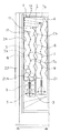
図1は、本発明の第1の実施例を示す商品収納装置1を備えた自動販売機の側断面図である。図に示すように、この自動販売機は、本体21と、本体21の前面開口部21aを開閉する扉22と、本体21内に配設された商品収納装置1等から構成されている。そして、この本体21は断熱箱体から構成され、内部の商品収納装置1内に収納された商品Sを図示しない冷却装置や加温装置によって冷却あるいは加温して販売することができる。
【0015】
商品収納装置1は、従来と同様に、商品を前方から投入する商品投入口11と、上下方向に蛇行状に延びて内部に投入商品を収納する商品収納通路2と、商品収納通路2の下方に配設され販売動作に基づいて商品収納通路2内に収納される商品Sを最下方から1個ずつ販売する商品搬出機構3を備える。また、本実施例の場合、商品収納装置1は前側の隣り合った2本の商品収納通路2から成る前側商品通路ユニット1aと、後ろ側の隣り合った2本の商品収納通路2から成る後側商品通路ユニット1bとから構成されている。
【0016】
前側商品通路ユニット1aにおける2本の商品収納通路2は、予め定められた間隙を介して左右方向に対向して配設された一対の側板4と、この側板4間の前部に配設され前側の商品収納通路(第1の商品収納通路)2aの前側通路壁を形成する前部通路案内板5と、側板4間の後部に配設され同様に後側の商品収納通路(第2の商品収納通路)2bの後側通路壁を形成する後部通路案内板6と、側板4間の略中央に配設され隣接する2本の商品収納通路2a、2bのそれぞれに向かう凸部7a、7bを上下方向交互に連続するように形成した通路仕切板(仕切部材)7と、前側の商品収納通路2aに向かう通路仕切板7の凸部(第1の凸部)7aからさらに前側の商品収納通路2a側に突出した位置に設けられた第1の通路規制部材8と、後側の商品収納通路2bに向かう通路仕切板7の凸部(第2の凸部)7bからさらに後側の商品収納通路2b側に突出した位置に設けられた第2の通路規制部材9とから構成されている。すなわち、側板4と前部通路案内板5と通路仕切板7と第1の通路規制部材8とから前側の商品収納通路2aが形成され、側板4と後部通路案内板6と通路仕切板7と第2の通路規制部材9とから後側の商品収納通路2bが形成されている。また、通路仕切板7の前後面は、前側の商品収納通路2aの壁面と後側の商品収納通路2bの壁面をそれぞれ形成し、前部通路案内板5および後部通路案内板6は、前後方向に向かう凹凸部を上下方向交互に形成して蛇行状に伸び、それぞれ前側の商品収納通路2aおよび後側の商品収納通路2bの通路壁を構成する。
【0017】
このように商品収納装置1を構成することにより、隣接する商品収納通路2a、2bを仕切る通路仕切板7の構造を簡単にすることができるとともに、商品収納通路2a、2b間の無駄なスペースを無くすことができる。さらに商品収納通路2a、2b内に通路規制部材8、9をそれぞれ配設することにより、商品収納通路2a、2bの前後方向の間隔を規制して投入商品Sの商品収納通路2a、2b内での縦立ち等を防止することができる。これによって、通路形成部材の製作が簡単で、商品収納効率が良く、商品詰まりが少ない商品収納装置1を提供することができる。
【0018】
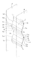
図2は本発明の前記実施例の通路仕切板7を示す部分斜視図である。図に示すように通路仕切板7は、前側の商品収納通路2aに向かう凸部7aを垂直面(第1の垂直面)7aaと該垂直面7aaの上下端部から後方に屈曲する上下斜面7ab、7acから構成し、後側の商品収納通路2bに向かう凸部7bを垂直面(第2の垂直面)7baと該垂直面7baの上下端部から前方に屈曲する上下斜面7bb、7bcから構成し、前側の商品収納通路2aに向かう凸部7aを構成する下斜面(第1の下斜面)7acと後側の商品収納通路2bに向かう凸部7bを構成する上斜面(第2の上斜面)7bbとが連続し、後側の商品収納通路2bに向かう凸部7bを構成する下斜面(第2の下斜面)7bcと前側の商品収納通路2aに向かう凸部7aを構成する上斜面(第1の上斜面)7abとが連続するように形成されている。
【0019】
このように通路仕切板7を、前後位置の異なる垂直面7aa、7baを上下に連ねて波形状に曲折する形状にすることにより、波形状の谷部に商品Sのはまり込みを防止して商品Sの流れを良くするとともに、波形状の振幅を小さくして、通路仕切板7を加工・製作するための金型等を簡易にすることができ、製造コストを引き下げることができる。
【0020】
さらに、第1の通路規制部材8および第2の通路規制部材9は、それぞれ通路仕切板7の前後面と平行に左右の側板間に横架された軸心8a、9aと、該軸心8a、9aを中心に回転自在に構成された棒状部材8b、9bから形成されている。これによって、商品収納通路2内を落下する商品Sが、通路規制部材8、9と当接するときの摩擦抵抗を少なくして商品Sの流れを良くし、商品収納通路2内での商品詰まりを少なくすることができる。
【0021】
以上のように前側商品通路ユニット1aは構成される。また、本発明の商品収納装置1を構成する後側商品通路ユニット1bについては、前側商品通路ユニット1aと略同様に構成される。
【0022】
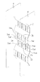
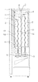
図3は本発明の第2の実施例を示す商品収納装置1を備えた自動販売機の側面断面図である。また、図4は前記第2の実施例の仕切板7を示す部分斜視図である。なお、図3および図4において、第1の実施例と同一部分には同一符号を付している。図に示すように、第2の実施例においては、前記第1の実施例において通路仕切板7の凸部7a、7bの商品収納通路2側にそれぞれ設けられた第1の通路規制部材8と第2の通路規制部材9に代わって、第1の通路規制突出部7adと第2の通路規制突出部7bdが、通路仕切板7の凸部7a、7bを構成する垂直面7aa、7baをそれぞれの商品収納通路2側に3箇所突出させて形成されている。このように構成することによって、通路仕切板7と第1の通路規制突出部7adおよび第2の通路規制突出部7bdを一体に形成することができ、部品点数および組立工数を削減することができ、製造コストを削減することができる。また、第1の通路規制突出部7adと第2の通路規制突出部7bdは上下端を通路仕切板7に支持されて中央部を突出して形成されるため、変形しずらく、またプレス加工により容易に形成可能である。このため、通路仕切板7の板厚を薄くすることが可能であるとともに、加工コストを安価にすることができる。ここで、通路仕切板7の凸部7aと凸部7b、および第1の通路規制突出部7adと第2の通路規制突出部7bdの形状を同様に形成することが望ましい。これによって、通路仕切板7は、その前後面の違いがなくなり、取り扱いを容易にして加工、組立をさらに容易にすることができる。
【0023】
また、商品通路壁を形成する前部通路案内板5および後部通路案内板6の上下方向の蛇行形状を、同様に形成することが望ましい。これによって、前部通路案内板5および後部通路案内板6を加工・製作するための金型等を共通にすることができ、製造コストを安くすることができるとともに、生産までのリードタイムを短くすることが可能である。
【0024】
なお、上記実施例においては、隣接する2本の商品収納通路2を備える商品通路ユニット1a、1bを前後方向に2列配設した商品収納装置1について説明したが、本発明はこの実施例に限られるものではなく、本発明の趣旨を包含する範囲で応用可能であり、例えば、3本以上の商品収納通路2を隣接して備える形態の自動販売機の商品収納装置1においても、応用実施可能である。
【0025】
以上説明したように請求項1に係る発明によれば、仕切部材の構造を簡単にするとともに、隣接する商品収納通路間の無駄なスペースをなくすことができ、さらに商品収納通路の前後方向の間隔を通路規制部材によって規制することで投入商品の商品収納通路内での縦立ち等を防止するとともに、商品収納通路内を落下する商品が商品規制部材と当接するときの摩擦抵抗を少なくして商品流れをスムーズにすることができる。これらによって、通路形成部材の製作が容易で、商品収納効率が良く、商品詰まりが少ない品質の良い自動販売機の商品収納装置を提供することが可能になる。
【図面の簡単な説明】
【図1】本発明の第1の実施例を示す商品収納装置を備えた自動販売機の側断面図である。
【図2】本発明の第1の実施例の通路仕切板を示す部分斜視図である。
【図3】本発明の第2の実施例を示す商品収納装置を備えた自動販売機の側断面図である。
【図4】本発明の第2の実施例の通路仕切板を示す部分斜視図である。
【図5】従来の商品収納装置を備える自動販売機の側断面を示す図である。
【符号の説明】
1 商品収納装置
2 商品収納通路
2a 前側の商品収納通路(第1の商品収納通路)
2b 後側の商品収納通路(第2の商品収納通路)
4 側板
7 通路仕切板(仕切部材)
7a 凸部(第1の凸部)
7aa 垂直面(第1の垂直面)
7ab 上斜面(第1の上斜面)
7ac 下斜面(第1の下斜面)
7ad 第1の通路規制突出部
7b 凸部(第2の凸部)
7ba 垂直面(第2の垂直面)
7bb 上斜面(第2の上斜面)
7bc 下斜面(第2の下斜面)
7bd 第2の通路規制突出部
8 第1の通路規制部材
8a 軸心
8b 棒状部材
9 第2の通路規制部材
8a 軸心
8b 棒状部材[0001]
BACKGROUND OF THE INVENTION
The present invention relates to a product storage device for a vending machine in which a plurality of rows of product storage passages are provided that meander in the vertical direction and extend and store products stacked therein.
[0002]
[Prior art]
FIG. 5 is a side sectional view showing a conventional vending machine equipped with such a conventional product storage device. As shown in the figure, the
[0003]
By the way, as shown in the figure, the
[0004]
The
[0005]
Therefore, a configuration described in Japanese Patent Laid-Open No. 8-77446 has already been proposed as a configuration for solving these problems. In this configuration, for example, a long corrugated passage forming member is disposed between adjacent product storage passages, and the corrugated shape is used to smoothly drop the product S in the product storage passage. A prevention member for preventing the product S from getting stuck in the valley portion is provided by cutting and raising. By comprising in this way, the number of parts which comprise a goods storage passage can be reduced, and the useless space of a partition part can be eliminated. In addition, it is possible to improve the flow of products in the product storage passage and reduce failures such as product clogging.
[0006]
[Problems to be solved by the invention]
By the way, in the configuration described in the above publication, the prevention member for preventing the product S from getting stuck is formed by cutting and raising a cantilevered plate piece in a valley portion of a passage forming member formed in a wave shape. . For this reason, when the plate | board thickness of a channel | path formation member is made thin, the intensity | strength of a cut-and-raised part will be weak and it will deform | transform easily. In addition, the peak portion of the passage forming member forms one wall surface of the product storage passage and has a function of preventing the product clogging by restricting the passage width by the protruding portion. It was necessary to form large. For this reason, in order to manufacture the passage forming member , it is necessary to process a thick steel plate into a wave shape with a large amplitude, which causes an increase in the size of the processing die and a decrease in productivity, resulting in an increase in manufacturing cost, etc. There was a problem.
[0007]
The present invention, along with lowering the production cost by readily processable with pleasure without and easy deformed shape such as a passage forming member, and reduce the number of parts, eliminates wasted space, in product storage passage An object of the present invention is to provide a product storage device for a vending machine that improves the flow of products and reduces failures such as product jams.
[0008]
[Means for Solving the Problems]
In order to solve the above-mentioned problems, the invention according to
[0009]
According to this configuration, the structure of the partition member can be simplified, and a useless space between adjacent product storage passages can be eliminated. Further, by regulating the interval in the front-rear direction of the product storage passage by the passage regulating member, it is possible to prevent the vertical standing of the input product in the product storage passage, and to smooth the flow of the product.
[0011]
Moreover, in the
[0013]
DETAILED DESCRIPTION OF THE INVENTION
Embodiments of the present invention will be described with reference to the drawings. In addition, the same code | symbol is used regarding the same structure as the past.
[0014]
FIG. 1 is a side sectional view of a vending machine including a
[0015]
As in the prior art, the
[0016]
The two
[0017]
By configuring the
[0018]
FIG. 2 is a partial perspective view showing the
[0019]
In this way, the
[0020]
Further, the first
[0021]
As described above, the front
[0022]
FIG. 3 is a side sectional view of a vending machine provided with a
[0023]
In addition, it is desirable that the front and rear
[0024]
In the above-described embodiment, the
[0025]
As described above, according to the first aspect of the present invention, the structure of the partition member can be simplified, the useless space between adjacent product storage passages can be eliminated, and the space between the product storage passages in the front-rear direction is further reduced. Is controlled by the passage restricting member to prevent the input product from standing upright in the product storage passage, and the product is reduced in friction resistance when the product falling in the product storage passage comes into contact with the product restricting member. The flow can be made smooth. Accordingly, it is possible to provide a merchandise storage device for a vending machine with a good quality, in which the passage forming member can be easily manufactured, the merchandise storage efficiency is good, and the product clogging is small.
[Brief description of the drawings]
FIG. 1 is a side sectional view of a vending machine provided with a product storage device according to a first embodiment of the present invention.
FIG. 2 is a partial perspective view showing a passage partition plate according to the first embodiment of the present invention.
FIG. 3 is a side sectional view of a vending machine equipped with a product storage device according to a second embodiment of the present invention.
FIG. 4 is a partial perspective view showing a passage partition plate according to a second embodiment of the present invention.
FIG. 5 is a side cross-sectional view of a vending machine including a conventional product storage device.
[Explanation of symbols]
DESCRIPTION OF
2b Rear product storage passage (second product storage passage)
4
7a Convex part (first convex part)
7aa Vertical plane (first vertical plane)
7ab upper slope (first upper slope)
7ac Lower slope (first lower slope)
7ad 1st channel | path
7ba Vertical plane (second vertical plane)
7bb Upper slope (second upper slope)
7bc Lower slope (second lower slope)
7bd Second passage
Claims (1)
隣接する第1の商品収納通路と第2の商品収納通路とを仕切るとともに、前記第1の商品収納通路に向かう第1の凸部と前記第2の商品収納通路に向かう第2の凸部とを上下方向交互に連続するように形成した板状部材からなり、その前後面が前記第1の商品収納通路と第2の商品収納通路の壁面をそれぞれ形成する仕切部材と、前記第1の凸部からさらに前記第1の商品収納通路側に突出した位置に設けられた第1の通路規制部材と、前記第2の凸部からさらに前記第2の商品収納通路側に突出した位置に設けられた第2の通路規制部材とを備え、前記第1の通路規制部材および前記第2の通路規制部材は、それぞれ前記第1の商品収納通路および第2の商品収納通路を左右方向に横断する棒状部材からなり、前記棒状部材はその軸心周りに回転自在に配設されたことを特徴とする自動販売機の商品収納装置。In a product storage device of a vending machine in which a plurality of product storage passages are arranged in parallel in the front-rear direction, meandering in the vertical direction between a pair of left and right side plates, and stacking and storing products inside.
The first product storage passage and the second product storage passage that are adjacent to each other are partitioned, and the first convex portion that faces the first product storage passage and the second convex portion that faces the second product storage passage, And a partition member whose front and rear surfaces respectively form the wall surfaces of the first product storage passage and the second product storage passage, and the first protrusions. A first passage regulating member provided at a position further projecting toward the first product storage passage from the portion, and a position projecting further toward the second product storage passage from the second convex portion. A second passage restricting member, and the first passage restricting member and the second passage restricting member are bar-shaped that traverse the first product storage passage and the second product storage passage in the left-right direction, respectively. The rod-shaped member is around its axis Product storage device of a vending machine, characterized in that is rotatably disposed.
Priority Applications (1)
| Application Number | Priority Date | Filing Date | Title |
|---|---|---|---|
| JP2001274583A JP4457539B2 (en) | 2001-09-11 | 2001-09-11 | Vending machine product storage device |
Applications Claiming Priority (1)
| Application Number | Priority Date | Filing Date | Title |
|---|---|---|---|
| JP2001274583A JP4457539B2 (en) | 2001-09-11 | 2001-09-11 | Vending machine product storage device |
Publications (2)
| Publication Number | Publication Date |
|---|---|
| JP2003085635A JP2003085635A (en) | 2003-03-20 |
| JP4457539B2 true JP4457539B2 (en) | 2010-04-28 |
Family
ID=19099589
Family Applications (1)
| Application Number | Title | Priority Date | Filing Date |
|---|---|---|---|
| JP2001274583A Expired - Fee Related JP4457539B2 (en) | 2001-09-11 | 2001-09-11 | Vending machine product storage device |
Country Status (1)
| Country | Link |
|---|---|
| JP (1) | JP4457539B2 (en) |
-
2001
- 2001-09-11 JP JP2001274583A patent/JP4457539B2/en not_active Expired - Fee Related
Also Published As
| Publication number | Publication date |
|---|---|
| JP2003085635A (en) | 2003-03-20 |
Similar Documents
| Publication | Publication Date | Title |
|---|---|---|
| US4287992A (en) | Rack structure | |
| GB2426727A (en) | Manufacture method for inner-fin tube and manufacture device for the same | |
| JP4457539B2 (en) | Vending machine product storage device | |
| US7118368B2 (en) | Mold table for food products and method of making said table | |
| US4691604A (en) | Anti-jamming die | |
| JP2001283314A (en) | Vending machine product unloading device | |
| JP4457541B2 (en) | Product storage device for vending machine and manufacturing method thereof | |
| JPH0877446A (en) | vending machine | |
| JPH0648081U (en) | vending machine | |
| JP2676566B2 (en) | Product storage shelves | |
| JP2009169746A (en) | Article chute for vending machine | |
| JP4360032B2 (en) | Vending machine product storage rack | |
| JP3208316B2 (en) | vending machine | |
| JP3360721B2 (en) | Baking mold and product collection method | |
| JPH06266946A (en) | Serpentine rack device for vending machines | |
| JP2018049555A (en) | Vending machine product storage device | |
| JP2003157468A (en) | Vending machine | |
| JP4930243B2 (en) | Product storage rack | |
| JPS6319897Y2 (en) | ||
| JP2001216562A (en) | Vending machine product unloading device | |
| JP4049076B2 (en) | vending machine | |
| JPH0716273U (en) | vending machine | |
| JP2002329246A (en) | Vending machine serpentine storage rack | |
| JPH10105821A (en) | Automatic vending machine | |
| JPH0684175U (en) | Fins for heat exchanger |
Legal Events
| Date | Code | Title | Description |
|---|---|---|---|
| RD02 | Notification of acceptance of power of attorney |
Free format text: JAPANESE INTERMEDIATE CODE: A7422 Effective date: 20060703 |
|
| RD04 | Notification of resignation of power of attorney |
Free format text: JAPANESE INTERMEDIATE CODE: A7424 Effective date: 20060704 |
|
| A621 | Written request for application examination |
Free format text: JAPANESE INTERMEDIATE CODE: A621 Effective date: 20080715 |
|
| RD02 | Notification of acceptance of power of attorney |
Free format text: JAPANESE INTERMEDIATE CODE: A7422 Effective date: 20081215 |
|
| RD04 | Notification of resignation of power of attorney |
Free format text: JAPANESE INTERMEDIATE CODE: A7424 Effective date: 20090219 |
|
| A977 | Report on retrieval |
Free format text: JAPANESE INTERMEDIATE CODE: A971007 Effective date: 20091016 |
|
| A131 | Notification of reasons for refusal |
Free format text: JAPANESE INTERMEDIATE CODE: A131 Effective date: 20091020 |
|
| A521 | Written amendment |
Free format text: JAPANESE INTERMEDIATE CODE: A523 Effective date: 20091217 |
|
| TRDD | Decision of grant or rejection written | ||
| A01 | Written decision to grant a patent or to grant a registration (utility model) |
Free format text: JAPANESE INTERMEDIATE CODE: A01 Effective date: 20100119 |
|
| A01 | Written decision to grant a patent or to grant a registration (utility model) |
Free format text: JAPANESE INTERMEDIATE CODE: A01 |
|
| A61 | First payment of annual fees (during grant procedure) |
Free format text: JAPANESE INTERMEDIATE CODE: A61 Effective date: 20100201 |
|
| R150 | Certificate of patent or registration of utility model |
Free format text: JAPANESE INTERMEDIATE CODE: R150 Ref document number: 4457539 Country of ref document: JP Free format text: JAPANESE INTERMEDIATE CODE: R150 |
|
| FPAY | Renewal fee payment (event date is renewal date of database) |
Free format text: PAYMENT UNTIL: 20130219 Year of fee payment: 3 |
|
| S531 | Written request for registration of change of domicile |
Free format text: JAPANESE INTERMEDIATE CODE: R313531 |
|
| FPAY | Renewal fee payment (event date is renewal date of database) |
Free format text: PAYMENT UNTIL: 20130219 Year of fee payment: 3 |
|
| R350 | Written notification of registration of transfer |
Free format text: JAPANESE INTERMEDIATE CODE: R350 |
|
| FPAY | Renewal fee payment (event date is renewal date of database) |
Free format text: PAYMENT UNTIL: 20130219 Year of fee payment: 3 |
|
| S111 | Request for change of ownership or part of ownership |
Free format text: JAPANESE INTERMEDIATE CODE: R313111 |
|
| FPAY | Renewal fee payment (event date is renewal date of database) |
Free format text: PAYMENT UNTIL: 20130219 Year of fee payment: 3 |
|
| R350 | Written notification of registration of transfer |
Free format text: JAPANESE INTERMEDIATE CODE: R350 |
|
| R250 | Receipt of annual fees |
Free format text: JAPANESE INTERMEDIATE CODE: R250 |
|
| R250 | Receipt of annual fees |
Free format text: JAPANESE INTERMEDIATE CODE: R250 |
|
| R250 | Receipt of annual fees |
Free format text: JAPANESE INTERMEDIATE CODE: R250 |
|
| R250 | Receipt of annual fees |
Free format text: JAPANESE INTERMEDIATE CODE: R250 |
|
| R250 | Receipt of annual fees |
Free format text: JAPANESE INTERMEDIATE CODE: R250 |
|
| R250 | Receipt of annual fees |
Free format text: JAPANESE INTERMEDIATE CODE: R250 |
|
| LAPS | Cancellation because of no payment of annual fees |