JP4476112B2 - Compressor drive unit - Google Patents
Compressor drive unit Download PDFInfo
- Publication number
- JP4476112B2 JP4476112B2 JP2004357057A JP2004357057A JP4476112B2 JP 4476112 B2 JP4476112 B2 JP 4476112B2 JP 2004357057 A JP2004357057 A JP 2004357057A JP 2004357057 A JP2004357057 A JP 2004357057A JP 4476112 B2 JP4476112 B2 JP 4476112B2
- Authority
- JP
- Japan
- Prior art keywords
- rotor
- rotational speed
- brushless motor
- compressor
- piston
- Prior art date
- Legal status (The legal status is an assumption and is not a legal conclusion. Google has not performed a legal analysis and makes no representation as to the accuracy of the status listed.)
- Expired - Fee Related
Links
Images
Landscapes
- Control Of Positive-Displacement Pumps (AREA)
- Control Of Motors That Do Not Use Commutators (AREA)
Description
この発明は圧縮機の駆動装置に関し、特に、シリンダ内でピストンを駆動させて気体を圧縮するブラシレスモータを備えた圧縮機において、ブラシレスモータを回転駆動させる駆動装置に関する。 The present invention relates to a drive device for a compressor, and more particularly, to a drive device that rotates a brushless motor in a compressor having a brushless motor that compresses gas by driving a piston in a cylinder.
従来より、圧縮機に含まれるブラシレスモータを駆動する方法として、回転子の回転に伴って固定子の電動子巻線に誘起される電圧を利用して回転子の位置を検出し、その検出結果に基づいてインバータを制御し、電動子巻線に電流を供給してブラシレスモータを駆動させるセンサレス方式が知られている。 Conventionally, as a method of driving a brushless motor included in a compressor, the position of the rotor is detected using the voltage induced in the stator winding of the stator as the rotor rotates, and the detection result There is known a sensorless system that controls an inverter based on the above and supplies a current to an armature winding to drive a brushless motor.
圧縮機の起動時は、回転子が停止した状態では電動子巻線に誘起電圧が発生しないため、まず所定の転流パルスをインバータに与えて回転子と固定子の相を一致させる相固定運転を行ない、次いで所定の転流パルスをインバータに与えて同期運転を行って回転子の回転数を上昇させ、位置検出が可能となる同期回転数に到達した後にセンサレス運転を行なう(たとえば特許文献1参照)。
しかし、従来の駆動方法では、単にインバータへの転流パルスの供給を停止して圧縮機を停止させていたので、圧縮機を停止させる毎にピストンがシリンダ内の任意の位置で停止し、圧縮機の起動時におけるモータの負荷トルクが起動毎に変化し、圧縮機の起動が不安定になるという問題があった。 However, in the conventional driving method, the compressor is stopped by simply stopping the supply of commutation pulses to the inverter, so the piston stops at an arbitrary position in the cylinder each time the compressor is stopped. There has been a problem that the load torque of the motor at the time of starting the machine changes every time it starts, and the starting of the compressor becomes unstable.
それゆえに、この発明の主たる目的は、圧縮機を安定に起動させることが可能な圧縮機の駆動装置を提供することである。 Therefore, a main object of the present invention is to provide a compressor drive device capable of stably starting a compressor.
この発明に係る圧縮機の駆動装置は、シリンダ内でピストンを駆動させて気体を圧縮するブラシレスモータを備えた圧縮機において、ブラシレスモータを回転駆動させる駆動装置であって、ブラシレスモータの複数の電動子巻線に駆動電流を供給するインバータと、複数の電動子巻線の誘起電圧に基づいて、ブラシレスモータの固定子に対する回転子の位置を検出する位置検出手段と、位置検出手段の検出結果に基づいてインバータを制御する制御手段を備えたものである。 A compressor driving device according to the present invention is a driving device that rotates a brushless motor in a compressor having a brushless motor that compresses gas by driving a piston in a cylinder, and includes a plurality of electric motors of the brushless motor. Based on the inverter that supplies the drive current to the child winding, the position detection means that detects the position of the rotor relative to the stator of the brushless motor based on the induced voltage of the plurality of armature windings, and the detection result of the position detection means those having a control unit for controlling the inverter based.
この制御手段は、圧縮機の駆動停止が指示されたことに応じて、回転子の回転数を低下させるセンサレス運転手段と、センサレス運転手段によって回転子の回転数が同期回転数に低下されたことに応じて、ブラシレスモータを同期運転させて回転子の回転数をさらに低下させる同期運転手段と、同期運転手段によって回転子の回転数が予め定められた回転数に低下されたことに応じて、ブラシレスモータを相固定運転させる相固定運転手段と、相固定運転手段によってブラシレスモータが相固定運転されたことに応じて、位置検出手段の検出結果に基づいて回転子を予め定められた位置に停止させる停止手段を含む。
好ましくは、ピストンは、シリンダ内において第1および第2の死点間で往復動する。ピストンが第1の死点から第2の死点に移動することによってシリンダ内に気体が吸い込まれ、ピストンが第2の死点から第1の死点に移動することによってシリンダ内において気体が圧縮され、回転子が予め定められた位置で停止したときピストンは第2の死点で停止する。 The control means, in response to the driving stop of the compressor is instructed, a sensorless operation means for reducing the rotational speed of the rotor, the rotational speed of the rotor is reduced to synchronous speed by sensorless operation means depending on the synchronous operation means for further reducing the rotational speed of the rotor by the synchronous operation of the brushless motor, in response to that is lowered to the rotational speed the rotational speed of the rotor is predetermined by the synchronous operation means, Phase-fixed operation means for phase-fixing operation of the brushless motor, and stopping the rotor at a predetermined position based on the detection result of the position detection means in response to the phase-less operation of the brushless motor by the phase-fixed operation means Including stopping means.
Preferably, the piston reciprocates between the first and second dead centers in the cylinder. Gas is sucked into the cylinder by moving the piston from the first dead center to the second dead center, and gas is compressed in the cylinder by moving the piston from the second dead center to the first dead center. When the rotor stops at a predetermined position, the piston stops at the second dead center.
この発明に係る圧縮機の駆動装置では、圧縮機の駆動停止が指示されたことに応じて、回転子の回転数を低下させ、回転子の回転数が同期回転数に低下されたことに応じて、ブラシレスモータを同期運転させて回転子の回転数をさらに低下させ、回転子の回転数が予め定められた回転数に低下されたことに応じてブラシレスモータを相固定運転させ、位置検出手段の検出結果に基づいて回転子を予め定められた位置に停止させる。したがって、ピストンを常に同じ位置で停止させることができるので、圧縮機の起動時におけるモータの負荷トルクを一定にすることができ、圧縮機を安定に起動させることができる。 In the compressor driving device according to the present invention, in response to an instruction to stop driving the compressor, the rotational speed of the rotor is decreased, and the rotational speed of the rotor is decreased to the synchronous rotational speed. The brushless motor is operated synchronously to further reduce the rotational speed of the rotor, and the brushless motor is phase-fixed in response to the rotational speed of the rotor being reduced to a predetermined rotational speed to detect the position. The rotor is stopped at a predetermined position based on the detection result. Therefore, since the piston can always be stopped at the same position, the load torque of the motor when starting the compressor can be made constant, and the compressor can be started stably.
実施の形態を説明する前に、まずこの発明の原理について説明する。この発明は、センサレスのブラシレスモータを備えた圧縮機においても、運転中の無通電相に発生する誘起電圧から回転子の位置情報を得て運転していることに着目し、その位置情報を回転子が停止に至るまで保持するものである。すなわち、圧縮機を運転させると、ピストンが1往復する時の負荷トルク変動に応じて回転子の回転速度が変化する。この回転子の回転速度の変化は、固定子に対する回転子の位置(ピストン位置)と相関がある。 Before describing the embodiment, the principle of the present invention will be described first. The present invention pays attention to the fact that a compressor equipped with a sensorless brushless motor is operated by obtaining position information of a rotor from an induced voltage generated in a non-energized phase during operation, and the position information is rotated. The child holds it until it stops. That is, when the compressor is operated, the rotational speed of the rotor changes according to the load torque fluctuation when the piston reciprocates once. This change in the rotational speed of the rotor has a correlation with the position of the rotor (piston position) with respect to the stator.
圧縮機を停止させる際、運転中に見つけた相関関係が崩れないように、回転子が停止するまで回転制御を行なう。起動時に同期運転からセンサレス運転モードに切換える同期回転数まではセンサレス運転で回転子の回転数を下げて行き、回転子の回転数が同期回転数に到達したら同期運転に切換え、さらに回転数を下げて相固定運転を行なう。相固定運転を行いながら、回転子が所定の位置になったときにインバータへの転流パルスの供給を停止してピストンを停止させる。このような制御を運転停止毎に行なうことで起動時のピストン位置を一定にし、圧縮機の起動の安定化を図る。以下、この発明について図面を用いて詳細に説明する。 When stopping the compressor, rotation control is performed until the rotor stops so that the correlation found during operation does not collapse. At the time of startup, the rotation speed of the rotor is reduced by the sensorless operation until the synchronous rotation speed is switched from the synchronous operation to the sensorless operation mode. When the rotation speed of the rotor reaches the synchronous rotation speed, the operation is switched to the synchronous operation, and the rotation speed is further reduced. Phase-fixed operation. While performing the phase locking operation, when the rotor reaches a predetermined position, the supply of the commutation pulse to the inverter is stopped to stop the piston. By performing such control every time the operation is stopped, the piston position at the time of starting is made constant, and the starting of the compressor is stabilized. The present invention will be described in detail below with reference to the drawings.
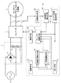
図1は、この発明の一実施の形態によるセンサレスDCブラシレスモータ圧縮機1の駆動装置の構成を示す回路ブロック図である。図1において、この駆動装置は、コンバータ3、インバータ7、位置検出手段8および制御装置9を備える。コンバータ3は、交流電圧を直流電圧に変換してインバータ7に与える。コンバータ3は、交流電源2から出力される交流電圧(たとえば100V)を整流して直流電圧(この場合は280V)を生成する倍電圧整流回路4と、生成された直流電圧を安定化させるコンデンサ5,6とを含む。
FIG. 1 is a circuit block diagram showing the configuration of a drive device for a sensorless DC
インバータ7は、制御装置9から与えられる転流パルスによって制御され、コンバータ3からの直流電圧を3相交流電圧に変換する。この3相交流電圧は、圧縮機1に含まれるブラシレスモータの3つの電動子巻線に与えられる。インバータ7は、3相ブリッジ接続された6つのトランジスタと、各トランジスタに逆並列に接続されたダイオードとを含む周知のものである。
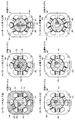
図2(a)〜(f)および図3(a)〜(f)は、圧縮機1の要部の構成および動作を示す図である。図2(a)〜(f)および図3(a)〜(f)において、圧縮機1のブラシレスモータは、固定子20と、その中心に回転自在に設けられた回転子22を含む。固定子20の内周側には、回転子22の外周面に向けて6つのポールP0〜P5が等角度間隔で突設されており、対向する2つのポールP0とP3,P1とP4,P2とP5の各々には、1つの電動子巻線21が巻回されている。3つの電動子巻線21に3相交流電流を流すことにより、ポールP0とP3,P1とP4,P2とP5の各々をS極またはN極に交互に変化させて回転磁界を発生させる。
2 (a) to 2 (f) and FIGS. 3 (a) to 3 (f) are diagrams showing the configuration and operation of the main part of the
また、回転子22の外周面には、永久磁石のN極とS極が交互に合せて4極配置されている。回転子22の端面の所定位置には、シャフトクランク23が取付けられ、シャフトの先端にはピストン24が固定されている。ピストン24は、シリンダ25内で往復動自在に設けられている。回転子22が1回転すると、ピストン24は1往復する。
Further, on the outer peripheral surface of the
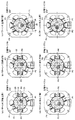
このような構成の圧縮機では、ピストン24が1往復するときの駆動パターンには12のパターン0〜11があることが分かっている。図2(a)〜(f)および図3(a)〜(f)は、それぞれパターン0〜11を示している。パターン11,0〜4は気体をシリンダ25内に吸込む吸込工程であり、パターン5〜8はシリンダ25内で気体を圧縮する圧縮工程であり、パターン9,10は圧縮された気体を排出弁(図示せず)を介して排出する排出工程である。
In the compressor having such a configuration, it is known that there are 12
詳しく説明すると、パターン0(吸込工程)では、ポールP0,P3がN極にされるとともにポールP1,P4がS極にされ、回転子22の2つのN極とポールP0,P3との反発力と、回転子22の2つのN極とポールP1,P4との吸引力とにより、シャフトクランク23は図中285度の位置から315度の位置まで回転移動する。これに応じてピストン24は図中上方向に移動し、シリンダ25内に気体が吸込まれる。
More specifically, in the pattern 0 (suction process), the poles P0 and P3 are set to the N pole and the poles P1 and P4 are set to the S pole, and the repulsive force between the two N poles of the
次にパターン1(吸込工程)では、ポールP0,P3がN極に維持されるとともにポールP2,P5がS極にされ、回転子22の2つのS極とポールP2,P5との反発力と、回転子22の2つのS極とポールP0,P3との吸引力とにより、シャフトクランク23は図中315度の位置から345度の位置まで回転移動する。これに応じてピストン24は図中上方向に移動し、シリンダ25内に気体が吸込まれる。
Next, in pattern 1 (suction process), the poles P0 and P3 are maintained at the N pole and the poles P2 and P5 are set at the S pole, and the repulsive force between the two S poles of the
次いでパターン2(吸込工程)では、ポールP1,P4がN極にされるとともにポールP2,P5がS極に維持され、回転子22の2つのN極とポールP1,P4との反発力と、回転子22の2つのN極とポールP2,P5との吸引力とにより、シャフトクランク23は図中345度の位置から15度の位置まで回転移動する。シャフトクランク23が0度の位置に到達してピストン24が上死点に到達した後、ピストン24は図中下側に移動するが、ピストン24の高速移動によってシリンダ25内が負圧になっているので、引き続き気体の吸込みが行なわれる。以下同様にして回転子22が図中時計針回転方向に回転し、パターン3,4(吸込工程)でも、パターン2と同様にして気体の吸込みが行なわれる。
Next, in pattern 2 (suction process), the poles P1 and P4 are set to the N pole and the poles P2 and P5 are maintained to the S pole, and the repulsive force between the two N poles of the
パターン5(圧縮工程)では、パターン2〜4に続いてピストン24が図中下方向に移動し、シリンダ25内の気体が圧縮されて負圧から正圧に転じる。パターン6〜8でシリンダ25内の気体がさらに圧縮され、パターン8ではシャフトクランク23が180度の位置に到達してピストン24が下死点に到達した後、ピストン24は図中上側に移動する。高速移動するピストン24の移動に遅延して、パターン9,10で排出弁(図示せず)が開き、シリンダ25内で圧縮された気体が排出弁を介して排出される。ピストン24がさらに上方向に移動してシャフトクランク23が255度の位置に到達すると、パターン11でシリンダ25内が負圧になって排出弁が閉じ、再度気体の吸込みが行なわれる。
In the pattern 5 (compression process), the
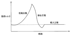
図4は、圧縮機1の負荷トルクの時刻変化を示す図である。図4において、気体がシリンダ25内に吸込まれる吸込工程では負荷トルクは低く略一定であるが、気体がシリンダ25内で圧縮される圧縮工程では負荷トルクが急激に上昇し、排出弁が開いてシリンダ25から気体が排出される排出工程では負荷トルクは急激に低下する。このように1サイクル内で負荷トルクが変化すると、それに応じてブラシレスモータの回転子22の回転速度が変化する。したがって、回転子22の回転速度の変化を検出することにより、負荷トルク、駆動パターン、ピストン24の位置を検出することができる。
FIG. 4 is a diagram showing the time change of the load torque of the
図1に戻って、位置検出手段8は、回転子22の回転に応じて3つの電動子巻線21に誘起される電圧を検出し、その検出結果に基づいてパターン0〜11に同期する位置検出信号を出力する。制御装置9は、位置検出手段8からの位置検出信号に基づいて転流パルスを生成し、インバータ7を制御する。
Returning to FIG. 1, the position detection means 8 detects the voltages induced in the three
すなわち制御装置9は、ソフトウェアで構成され、回転速度検出手段10、ピストン位置検出手段11、デューティ調整手段12、転流手段13、相固定運転手段14、同期運転手段15、起動手段16、および停止手段17を含む。
That is, the
回転速度検出手段10は、位置検出手段8から与えられる位置検出信号の間隔を検出し、その検出結果に基づいて回転子22の回転速度およびその変化パターンを検出する。ピストン位置検出手段11は、回転速度検出手段10によって検出された回転速度の変化パターンと、図4で示した予め記憶している負荷トルクの変化パターンとを比較し、現時点の駆動パターンがパターン0〜11のうちのいずれのパターンであるかを検出し、さらにピストン24のシリンダ25内における現在位置を検出する。
The rotation speed detection means 10 detects the interval of the position detection signals given from the position detection means 8, and detects the rotation speed of the
デューティ調整手段12は、センサレス運転時には、回転速度検出手段10で検出された固定子22の回転速度と、ピストン位置検出手段11で検出されたピストン24の位置とに基づいてデューティを調整し、調整したデューティを示す信号を転流手段13に与える。転流手段13は、デューティ調整手段12から与えられたデューティを示す信号に基づいて転流パルスを生成し、その転流パルスによってインバータ7を制御する。
During sensorless operation, the
相固定運転手段14は、起動手段16および停止手段17によって制御され、相固定運転を指示する信号をデューティ調整手段12に与える。その信号に応答してデューティ調整手段12は、転流手段13およびインバータ7を介して圧縮機1のブラシレスモータを相固定運転させる。ここで、相固定運転とは、予め定められた低い周波数の3相交流電圧をブラシレスモータに供給し、低い周波数の回転磁界を発生させて固定子20と回転子22の相を一致させる運転である。相固定運転は、一般には、同期運転の始動性を高めるために同期運転前に行なわれるが、本願発明では圧縮機の停止動作時にも行なわれる。この相固定モードでは、固定子22の回転速度は遅いので、インバータ7への転流パルスの供給を停止すると、固定子20が即座に停止する。なお、固定子22が高速で回転しているときに転流パルスの供給を停止しても、回転子22は即座には停止せず、慣性で回転し続ける。
The phase fixed operation means 14 is controlled by the start means 16 and the stop means 17 and gives a signal instructing the phase fixed operation to the duty adjustment means 12. In response to the signal, the duty adjustment means 12 causes the brushless motor of the
同期運転手段15は、起動手段16および停止手段17によって制御され、同期運転モードを指示する信号をデューティ調整手段12に与える。その信号に応答してデューティ調整手段12は、転流手段13およびインバータ7を介して圧縮機1のブラシレスモータを同期運転させる。ここで、同期運転とは、一般には、ブラシレスモータの起動時は電動子巻線22に誘起される電圧が低く、位置検出手段8が誘起電圧を検出することができないので、誘起電圧の検出が可能となる回転速度まで強制的に転流、加速を行ない、センサレス運転への準備を行なうものであるが、本願発明では圧縮機1の停止動作時にも行なわれる。同期運転手段12は、ブラシレスモータの停止前に同期運転が指示されたことに応じて、相固定運転が可能となる回転速度まで強制的に転流、減速を行ない、相固定運転への準備を行なう。
The synchronous operation means 15 is controlled by the start means 16 and the stop means 17 and gives a signal instructing the synchronous operation mode to the duty adjustment means 12. In response to the signal, the duty adjustment means 12 causes the brushless motor of the
起動手段16は、圧縮機1の起動が指示されたことに応じて相固定運転手段14に相固定運転の開始を指示し、所定時間後に相固定運転を停止させるとともに同期運転手段15に同期運転の開始を指示し、回転子22の回転数が同期回転数に到達したことに応じて同期運転を停止させる。起動時の同期運転が停止されると、デューティ調整手段12によってセンサレス運転が開始される。
The starting means 16 instructs the phase-fixed operation means 14 to start the phase-fixed operation in response to the start-up of the
停止手段17は、圧縮機1の停止が指示されたことに応じて、デューティ調整手段12に減速運転の開始を指示する信号を与える。その信号に応答してデューティ調整手段12は、転流手段13およびインバータ7を介して圧縮機1のブラシレスモータの回転数を徐々に低下させる。停止手段17は、回転速度検出手段10の検出結果に基づき、回転子22の回転数が同期回転数に到達したことに応じて同期運転手段15に同期運転の開始を指示する信号を同期運転手段15に与える。その信号に応答して同期運転手段15は、回転子22の回転数を徐々に低下させる。
The stop means 17 gives a signal instructing the duty adjustment means 12 to start the deceleration operation in response to an instruction to stop the
停止手段17は、回転速度検出手段10の検出結果に基づき、回転子22の回転数が予め定められた回転数に到達したことに応じて、同期運転手段15に同期運転を停止させるとともに相固定手段14に相固定運転の開始を指示する信号を相固定運転手段14に与える。停止手段17は、相固定運転が所定時間行なわれた後に、ピストン位置検出手段11の検出結果に基づき、相固定運転を停止させ、固定子22を予め定められた位置(たとえば図2(c)のパターン2の位置)に停止させてピストン24を停止させる。
Based on the detection result of the rotation speed detection means 10, the stop means 17 causes the synchronous operation means 15 to stop the synchronous operation and phase-lock in response to the rotation speed of the
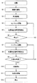
図5は、図1に示した制御装置9の動作を示すフローチャートである。図5において、ステップS1においてブラシレスモータの起動が指示され、ステップS2において相固定運転が指示され、所定の転流パルスがインバータ7に与えられて回転子22と固定子20の相を一致させる相固定運転が行なわれる。次いでステップS3において同期運転が指示され、所定の転流パルスがインバータ7に与えられて電動子巻線21の誘起電圧の検出が可能になるまで回転子22の回転数を上昇させる同期運転が行なわれる。回転子22の回転数が誘起電圧の検出が可能な同期回転数に到達すると、ステップS4でセンサレス運転が開始される。
FIG. 5 is a flowchart showing the operation of the
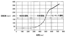
図6は、ブラシレスモータの起動時において、固定子20で生成される回転磁界の回転数の時刻変化を示す図である。図6において、最初の250msでは、回転磁界の回転数は略25rpmに固定されて相固定運転が行なわれる。次いで同期運転が行われて回転磁界および回転子22の回転数が300rpmに到達すると、センサレス運転が行われ、回転磁界および回転子22は所望の回転数に設定される。
FIG. 6 is a diagram showing the time change of the rotational speed of the rotating magnetic field generated by the
センサレス運転の期間は、ステップS5において位置検出信号の間隔が検出され、その検出結果に基づいて回転速度、ピストン位置が検出され、それらの検出結果に基づいて所望の回転数が維持される。センサレス運転中は、図4で示した負荷トルク変動を伴いながら、気体圧縮動作が行なわれる。 During the sensorless operation, the position detection signal interval is detected in step S5, the rotation speed and the piston position are detected based on the detection result, and the desired rotation speed is maintained based on the detection result. During the sensorless operation, the gas compression operation is performed with the load torque fluctuation shown in FIG.
次にステップS6において、圧縮機1の停止が指示されたかどうかを判別し、圧縮機1の停止が指示されていない場合はステップS4に戻り、圧縮機1の停止が指示されている場合はステップS7に進む。
Next, in step S6, it is determined whether or not the stop of the
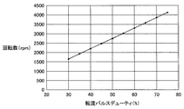
ステップS7ではセンサレス運転が行なわれ、ステップS8では位置検出信号の間隔が検出され、その検出結果に基づいて回転速度、ピストン位置が検出され、それらの検出結果に基づいて、転流パルスを制御しながら回転数を低下させて行く。このとき、図7に示される転流パルスデューティ(%)と回転数(rpm)の関係からソフトウェアにて圧縮機1のDC特性を算出し、転流パルスデューティを徐々に下げて行く。
In step S7, sensorless operation is performed. In step S8, the interval of the position detection signal is detected. Based on the detection result, the rotational speed and the piston position are detected, and the commutation pulse is controlled based on the detection result. While decreasing the rotation speed. At this time, the DC characteristics of the
ステップS9において、起動時に同期運転からセンサレス運転に切換えた同期回転数(300rpm)に回転子22の回転数が到達したかどうかを判別し、同期回転数に到達していない場合はステップS7に戻り、同期回転数に到達した場合はステップS10に進む。
In step S9, it is determined whether or not the rotational speed of the
ステップS10では同期運転が指示され、所定の転流パルスがインバータ7に与えられて相固定運転が可能になるまで回転子22の回転数を低下させる同期運転が行なわれる。回転子22の回転数が相固定運転が可能な回転数(たとえば20rpm)に到達すると、ステップS11において相固定運転が指示され、所定の転流パルスがインバータ7に与えられて回転子22と固定子20の相を一致させる相固定運転が行なわれる。ステップS12において、ピストン24がシリンダ25内の所定の位置に到達したことが検出され、インバータ7への転流パルスの供給が停止されて回転子22の回転が停止され、ピストン24が停止される。
In step S10, a synchronous operation is instructed, and a predetermined commutation pulse is applied to the
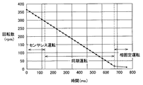
図8は、ブラシレスモータの停止時において、固定子20で生成される回転磁界の回転数の時刻変化を示す図である。図8において、圧縮機1の停止が指示されると、センサレス運転において回転磁界の回転数が徐々に低下される。回転子22の回転数が300rpmに到達すると、同期運転が行われ、回転磁界の回転数はさらに低下される。回転子22の回転数が20rpmに到達すると、回転数が固定されて相固定運転が行なわれる。ピストン24が所定の位置に到達すると、インバータ7への転流パルスの供給が停止されて回転子22の回転が停止され、ピストン24が停止される。
FIG. 8 is a diagram illustrating the time change of the rotational speed of the rotating magnetic field generated by the
この実施の形態では、圧縮機1の停止が指示されたことに応じて回転数を徐々に低下させ、所定の回転数に到達したことに応じて相固定運転を行ない、ピストン24を所定の位置に停止させる。したがって、起動時の負荷トルクを一定にすることができ、起動動作の安定化を図ることができる。
In this embodiment, the rotational speed is gradually decreased in response to an instruction to stop the
今回開示された実施の形態はすべての点で例示であって制限的なものではないと考えられるべきである。本発明の範囲は上記した説明ではなくて特許請求の範囲によって示され、特許請求の範囲と均等の意味および範囲内でのすべての変更が含まれることが意図される。 The embodiment disclosed this time should be considered as illustrative in all points and not restrictive. The scope of the present invention is defined by the terms of the claims, rather than the description above, and is intended to include any modifications within the scope and meaning equivalent to the terms of the claims.
1 圧縮機、2 交流電源、3 コンバータ、4 倍電圧整流回路、5,6 コンデンサ、7 インバータ、8 位置検出手段、9 制御装置、10 回転速度検出手段、11 ピストン位置検出手段、12 デューティ調整手段、13 転流手段、14 相固定運転手段、15 同期運転手段、16 起動手段、17 停止手段、20 固定子、21 電動子巻線、22 回転子、23 シャフトクランク、24 ピストン、25 シリンダ、P0〜P5 ポール。
DESCRIPTION OF
Claims (2)
前記ブラシレスモータの複数の電動子巻線に駆動電流を供給するインバータ、
前記複数の電動子巻線の誘起電圧に基づいて、前記ブラシレスモータの固定子に対する回転子の位置を検出する位置検出手段、および
前記位置検出手段の検出結果に基づいて前記インバータを制御する制御手段を備え、
前記制御手段は、
前記圧縮機の駆動停止が指示されたことに応じて、前記回転子の回転数を低下させるセンサレス運転手段、
前記センサレス運転手段によって前記回転子の回転数が同期回転数に低下されたことに応じて、前記ブラシレスモータを同期運転させて前記回転子の回転数をさらに低下させる同期運転手段、
前記同期運転手段によって前記回転子の回転数が予め定められた回転数に低下されたことに応じて、前記ブラシレスモータを相固定運転させる相固定運転手段、および
前記相固定運転手段によって前記ブラシレスモータが相固定運転されたことに応じて、前記位置検出手段の検出結果に基づいて前記回転子を予め定められた位置に停止させる停止手段を含むことを特徴とする、圧縮機の駆動装置。 In a compressor provided with a brushless motor that compresses gas by driving a piston in a cylinder, the drive device that rotationally drives the brushless motor,
An inverter for supplying a drive current to a plurality of armature windings of the brushless motor;
Position detecting means for detecting a position of a rotor relative to a stator of the brushless motor based on induced voltages of the plurality of armature windings; and control means for controlling the inverter based on a detection result of the position detecting means. With
Wherein,
Sensorless operation means for reducing the rotational speed of the rotor in response to an instruction to stop driving the compressor ;
Synchronous operation means for further reducing the rotational speed of the rotor by synchronously operating the brushless motor in response to the rotational speed of the rotor being reduced to the synchronous rotational speed by the sensorless operating means;
In response to the lowered rotational speed rotational speed is predetermined for the rotor by the synchronous operation unit, the brushless motor phase fixed operation is allowed Ru phase fixed driving means, and
Characterized by comprising stop means for stopping the rotor at a predetermined position based on a detection result of the position detection means in response to the brushless motor being phase-fixed by the phase-fixing operation means. A compressor drive device.
前記ピストンが前記第1の死点から第2の死点に移動することによって前記シリンダ内に前記気体が吸い込まれ、前記ピストンが前記第2の死点から第1の死点に移動することによって前記シリンダ内において前記気体が圧縮され、
前記回転子が前記予め定められた位置で停止したとき前記ピストンは前記第2の死点で停止することを特徴とする、請求項1に記載の圧縮機の駆動装置。 The piston reciprocates between first and second dead centers in the cylinder;
When the piston moves from the first dead center to the second dead center, the gas is sucked into the cylinder, and the piston moves from the second dead center to the first dead center. The gas is compressed in the cylinder;
It is the piston when the front SL rotor is stopped at a position where said predetermined, characterized in that stops at the second dead center, the driving device of the compressor according to claim 1.
Priority Applications (1)
| Application Number | Priority Date | Filing Date | Title |
|---|---|---|---|
| JP2004357057A JP4476112B2 (en) | 2004-12-09 | 2004-12-09 | Compressor drive unit |
Applications Claiming Priority (1)
| Application Number | Priority Date | Filing Date | Title |
|---|---|---|---|
| JP2004357057A JP4476112B2 (en) | 2004-12-09 | 2004-12-09 | Compressor drive unit |
Publications (2)
| Publication Number | Publication Date |
|---|---|
| JP2006166658A JP2006166658A (en) | 2006-06-22 |
| JP4476112B2 true JP4476112B2 (en) | 2010-06-09 |
Family
ID=36668039
Family Applications (1)
| Application Number | Title | Priority Date | Filing Date |
|---|---|---|---|
| JP2004357057A Expired - Fee Related JP4476112B2 (en) | 2004-12-09 | 2004-12-09 | Compressor drive unit |
Country Status (1)
| Country | Link |
|---|---|
| JP (1) | JP4476112B2 (en) |
Families Citing this family (5)
| Publication number | Priority date | Publication date | Assignee | Title |
|---|---|---|---|---|
| JP5119025B2 (en) | 2008-03-31 | 2013-01-16 | 株式会社日立産機システム | Motor control device, air compressor, air conditioner, passenger conveyor control device and conveyor control device |
| KR101367680B1 (en) | 2012-10-29 | 2014-03-12 | 삼성전기주식회사 | Apparatus for generating control signal for driving a motor |
| JP6610461B2 (en) * | 2016-07-27 | 2019-11-27 | アイシン精機株式会社 | Crank mechanism motor and vacuum pump |
| KR102342001B1 (en) * | 2020-05-26 | 2021-12-24 | 어보브반도체 주식회사 | Control apparatus of compressor and method for controlling compressor |
| CN112460771A (en) * | 2020-11-30 | 2021-03-09 | 珠海格力电器股份有限公司 | Compressor control method, device and system and storage medium |
-
2004
- 2004-12-09 JP JP2004357057A patent/JP4476112B2/en not_active Expired - Fee Related
Also Published As
| Publication number | Publication date |
|---|---|
| JP2006166658A (en) | 2006-06-22 |
Similar Documents
| Publication | Publication Date | Title |
|---|---|---|
| CN102239630B (en) | Motor drive device, and compressor and refrigerator using same | |
| US8084970B2 (en) | Electrical machine and method of controlling the same | |
| EP1375907B1 (en) | Engine starting device | |
| US8242725B2 (en) | Method for operating sensorless and brushless motors | |
| WO2004084401A1 (en) | Electrically powered compressor | |
| EP1612925A3 (en) | A brushless DC motor controller | |
| JP4515432B2 (en) | Compressor drive method | |
| KR20080103846A (en) | Motor control device and method | |
| JP4476112B2 (en) | Compressor drive unit | |
| JP3672637B2 (en) | Compressor motor control device | |
| JP2007092686A (en) | Compressor drive unit | |
| JP2015065730A (en) | Motor start-up controller and air compressor | |
| CN115839332B (en) | A method for starting a piston compressor and a compressor starting device | |
| KR100859077B1 (en) | Start control method of compressor drive motor | |
| WO2007116730A1 (en) | Apparatus and method for controlling reciprocal compressor | |
| JP4289003B2 (en) | Method and apparatus for driving brushless DC motor | |
| JP4531180B2 (en) | Synchronous motor and method for starting synchronous motor | |
| JPH09327194A (en) | Control method of brushless motor | |
| JP2015065729A (en) | Motor start-up controller and air compressor | |
| JP4046266B2 (en) | Starting method of brushless rotating electrical machine for driving internal combustion engine | |
| JP3283377B2 (en) | DC motor synchronous starter | |
| KR100677876B1 (en) | Alignment control method of brushless DC motor | |
| JP2004328850A (en) | How to start compressor motor of inverter refrigerator | |
| KR20100058203A (en) | Control method of compressor | |
| EP1753123A2 (en) | Methods and apparatus for controlling a motor/generator |
Legal Events
| Date | Code | Title | Description |
|---|---|---|---|
| A621 | Written request for application examination |
Free format text: JAPANESE INTERMEDIATE CODE: A621 Effective date: 20070302 |
|
| A977 | Report on retrieval |
Free format text: JAPANESE INTERMEDIATE CODE: A971007 Effective date: 20091124 |
|
| A131 | Notification of reasons for refusal |
Free format text: JAPANESE INTERMEDIATE CODE: A131 Effective date: 20091201 |
|
| A521 | Written amendment |
Free format text: JAPANESE INTERMEDIATE CODE: A523 Effective date: 20100125 |
|
| TRDD | Decision of grant or rejection written | ||
| A01 | Written decision to grant a patent or to grant a registration (utility model) |
Free format text: JAPANESE INTERMEDIATE CODE: A01 Effective date: 20100302 |
|
| A01 | Written decision to grant a patent or to grant a registration (utility model) |
Free format text: JAPANESE INTERMEDIATE CODE: A01 |
|
| A61 | First payment of annual fees (during grant procedure) |
Free format text: JAPANESE INTERMEDIATE CODE: A61 Effective date: 20100309 |
|
| R150 | Certificate of patent or registration of utility model |
Free format text: JAPANESE INTERMEDIATE CODE: R150 |
|
| FPAY | Renewal fee payment (event date is renewal date of database) |
Free format text: PAYMENT UNTIL: 20130319 Year of fee payment: 3 |
|
| FPAY | Renewal fee payment (event date is renewal date of database) |
Free format text: PAYMENT UNTIL: 20130319 Year of fee payment: 3 |
|
| FPAY | Renewal fee payment (event date is renewal date of database) |
Free format text: PAYMENT UNTIL: 20140319 Year of fee payment: 4 |
|
| LAPS | Cancellation because of no payment of annual fees |