JP4491994B2 - Coil device for automotive glass antenna - Google Patents
Coil device for automotive glass antenna Download PDFInfo
- Publication number
- JP4491994B2 JP4491994B2 JP2001191370A JP2001191370A JP4491994B2 JP 4491994 B2 JP4491994 B2 JP 4491994B2 JP 2001191370 A JP2001191370 A JP 2001191370A JP 2001191370 A JP2001191370 A JP 2001191370A JP 4491994 B2 JP4491994 B2 JP 4491994B2
- Authority
- JP
- Japan
- Prior art keywords
- circuit board
- choke coil
- leg
- frequency choke
- coil
- Prior art date
- Legal status (The legal status is an assumption and is not a legal conclusion. Google has not performed a legal analysis and makes no representation as to the accuracy of the status listed.)
- Expired - Fee Related
Links
Images


Landscapes
- Coils Or Transformers For Communication (AREA)
- Details Of Aerials (AREA)
Description
【0001】
【発明の属する技術分野】
本発明は、自動車ガラスアンテナ用のコイル装置に関する。
【0002】
【従来の技術】
従来、図3に示すとおり、多数本のヒータ線22とヒータ線22に給電する複数のバスバ15a、15b、15cとを有する通電加熱式のデフォッガ23が自動車の後部窓ガラス板21に設けられており、バスバ15a、15bと直流電源10との間にチョークコイル19及び高周波チョークコイル1(後述する図2における高周波チョークコイル31に相当)が接続されている自動車用ガラスアンテナが知られている。
【0003】
この従来例では、デフォッガ23の給電点14にケーブル27を接続して、
デフォッガ23に励起された受信信号をデフォッガ23の給電点14、ケーブル27を介して、受信機20に送っていた。
【0004】
この従来例で用いていたコイル装置を図2に示した(特開平5−75321号参照)。この従来のコイル装置では、樹脂製のケース34にコイル芯32に巻かれた高周波チョークコイル31が収納され、コイルの一端35aは脚部33aと電気的に接続され、コイルの他端35bは脚部33c及び端子片33bと電気的に接続されていた。
【0005】
脚部33aはバスバ15a上に半田にて接着され、脚部33cはダミーパターン(不図示)上に半田にて接着されており、端子片33bがチョークコイル19にリード線28を介して接続されていた。
【0006】
このため、デフォッガの給電点14をバスバ15aとは別に設ける必要があり、後部窓ガラス板21の有効なスペース利用の点で無駄となる問題があった。また、デフォッガの給電点14にケーブル27を接続する工程が必要になり、生産性が悪い問題があった。
【0007】
さらに、デフォッガの給電点14を設ける代わりに給電点をバスバ上に設けようとしても、車種によってはバスバが窓枠に隠れるため、複数の端子をバスバ上に設けることができない問題もあった。
【0008】
【発明が解決しようとする課題】
本発明は、従来技術の有する前述の欠点を解消する自動車ガラスアンテナ用のコイル装置の提供を目的とする。
【0009】
【課題を解決するための手段】
本発明は、前述の課題を解決すべくなされたものであり、高周波チョークコイルと、回路基板と、ケーブルとが備えられており、
回路基板の片側には金属製の第1の脚部が設けられ、回路基板の他の側には金属製の第2の脚部が設けられており、さらに、回路基板には金属製の端子片が設けられており、
回路基板には少なくとも3つの孔が設けられており、
高周波チョークコイルの一端は第1の孔に挿入されて固着手段により回路基板に固着されており、
高周波チョークコイルの他端は第2の孔に挿入されて固着手段により回路基板に固着されており、
回路基板の上面と高周波チョークコイルの下部との間には所定の間隔が設けられ、高周波チョークコイルの下方の回路基板の箇所には第3の孔が設けられ、さらに、ケーブルの一端は第3の孔に挿入されて固着手段により回路基板に固着されており、
高周波チョークコイルの一端と、第1の脚部と、ケーブルの一端とは電気的に接続されており、
高周波チョークコイルの他端と端子片とは電気的に接続されていることを特徴とする自動車ガラスアンテナ用のコイル装置を提供する。
【0010】
【発明の実施の形態】
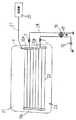
以下、本発明を図面に従って詳細に説明する。図1は本発明の自動車ガラスアンテナ用のコイル装置の一実施例の構成図である。
【0011】
図1において、1は高周波チョークコイル、2はコイル芯、3は金属製の端子片、4は回路基板、5aは高周波チョーク1のコイルの一端、5bは高周波チョークコイル1の他端、6aは金属製の第1の脚部、6bは金属製の第2の脚部、7はケーブル、7aはケーブルの一端、8は必要に応じて設けられるコンデンサ、9a、9b、9cは半田、Lは回路基板4の上面と高周波チョークコイル1の下部との間隔である。
【0012】
本発明の自動車ガラスアンテナ用のコイル装置には、高周波チョークコイル1と、回路基板4と、ケーブル7とが備えられている。回路基板4の片側には第1の脚部6aが設けられ、回路基板4の他の側には第2の脚部6bが設けられている。脚部6a、6bをそれぞれ回路基板4に設ける手段は、ハトメ金具等の金属片により、回路基板4と脚部6a、6bとをそれぞれ挟み込んでもよく、回路基板4の上に設けられた導体パターンと脚部6a、6bとをそれぞれ半田等により接着してもよく、脚部6a、6bを回路基板4に接着剤によりそれぞれ接着してもよく、特に限定されない。
【0013】
他端5bと第2の脚部6bとの間の回路基板4の箇所には金属製の端子片3が設けられている。図1では端子片3は回路基板4の上面から上方に伸長している。端子片3を回路基板4に設ける手段は、上記した脚部6a、脚部6bを回路基板4に設ける手段と同様である。
【0014】
回路基板4には3つの孔(不図示)が設けられており、一端5aは第1の孔に挿入されて半田付け等の固着手段により回路基板1に固着されている。高周波チョークコイル1の他端5bは第2の孔に挿入されて半田付け等の固着手段により回路基板4に固着されている。
【0015】
回路基板4の上面と高周波チョークコイル1の下部との間には所定の間隔Lが設けられている。高周波チョークコイル1の下方の回路基板4の箇所には第3の孔が設けられ、一端7a近傍は回路基板4の上面と高周波チョークコイル1の下部との間に配され、さらに、一端7aは第3の孔に挿入されて半田付け等の固着手段により回路基板4に固着されている。
【0016】
一端5aと、第1の脚部6aと、一端7aとは半田付け等の接続手段により電気的に接続されている。他端5bと端子片3とは半田付け等の接続手段により電気的に接続されている。他端5bと第2の脚部6bとは半田付け等の接続手段により電気的に接続されていてもよいが電気的に接続されていない方が好ましい。その理由は、第1の脚部6aと第2の脚部6bとが同じバスバに固着しても一端5aと他端5bとが短絡しないからである。なお、第1の脚部6aと第2の脚部6bとを同じバスバに固着する場合には、ダミーパターンは不要である。
【0017】
コイル芯2の形状は円筒形が好ましい。コイル芯2の材料としては、フェライト、センダスト等が通常用いられるが、これに限定されず、高周波特性を向上させるものであれば他の材料も使用できる。
【0018】
コンデンサ8は、第1の脚部6aとケーブル7との間に電気的に接続されるように必要に応じて設けられるものである。すなわち、本発明の自動車ガラスアンテナ用のコイル装置が後部窓ガラス板21に取付けられる場合には、コンデンサ8は、受信機20の入力端とバスバとの間に電気的に接続されるようになり、直流阻止の機能を有する。コンデンサ8が、第1の脚部6aとケーブル7との間に電気的に接続されるようにするには、回路基板4に設けられた導体パターンによるものであっても、他の手段であってもよい。
【0019】
図3に示す自動車用ガラスアンテナ装置に本発明の自動車ガラスアンテナ用のコイル装置が使用できる。例えば、第1の脚部6a及び第2の脚部6bをバスバ15aに半田付けする。ケーブル7の他端(不図示)は受信機20の入力端に電気的に接続する。
【0020】
バスバ15a、15bと直流電源10との間に、チョークコイル19と高周波チョークコイル1との直列接続回路を接続し、AM放送帯にてチョークコイル19のインピーダンスを大きくすることによって、直流電源10からデフォッガ23へ直流電流は流すものの、放送帯域の受信信号電流は遮断している。デフォッガ23に励起されるAM放送帯の受信電流が車体にできるだけ漏れないようにするためである。
【0021】
高周波チョークコイル1は、FM放送帯等の高周波帯において、高インピーダンスとなるもので、これらはFM放送帯等の高周波帯では誘導性のインダクタンスを有する。
【0022】
FM放送帯等の高周波帯においては、チョークコイル19の自己共振周波数が低く、チョークコイル19のインピーダンスに容量性が現れて通常低インピーダンスとなるので、高周波チョークコイル1がこれを代行する。なお、11はノイズ吸収用のコンデンサである。高周波チョークコイル1は0.1〜100μH程度が通常使用される。
【0023】
ここで、高周波帯としては、FM放送帯の他、テレビVHF帯(90〜108MHz、170〜222MHz)、テレビUHF帯(470〜770MHz)、北米及び欧州のテレビVHF帯(45〜86MHz、175〜225MHz)、自動車電話用の800MHz帯(810〜960MHz)、自動車電話用の1.5GHz帯(1.429〜1.501GHz)及びUHF帯(300MHz〜3GHz)等が挙げられる。
【0024】
【実施例】
図1に示すような自動車ガラスアンテナ用のコイル装置を製作した。各部の寸法、定数等の仕様は以下のとおりである。脚部6aは、脚部6aに孔(不図示)を設け、この孔と第1の孔とを合わせ、円筒状のハトメ金具を両孔に貫通させてかしめることにより回路基板4に固着した。脚部6bも回路基板4に設けた第4の孔(不図示)を用いて同様の手段で回路基板4に固着した。一端5aは第1の孔に貫通させたハトメ金具に挿入させて半田付けした。
【0025】
端子3は端子3に孔(不図示)を設け、この孔と第2の孔とを合わせ、円筒状のハトメ金具を両孔に貫通させてかしめることにより回路基板4に固着した。他端5bは第2の孔に貫通させたハトメ金具に挿入させて半田付けした。ケーブル7としては樹脂被膜付きの銅製のリード線を用いた。
高周波チョークコイル1の巻き数 8ターン、
高周波チョークコイル1の巻線の直径 1.6mm、
高周波チョークコイル1の巻線の材質 銅、
コイル芯2の形状 円筒形、
コイル芯2の直径 3.5mm、
コイル芯2の円筒の長さ 17.0mm、
コイル芯2の材質 Mn−Znフェライト、
脚部6a、6bの材質 銅の表面に錫メッキを施したもの、
端子片3の材質 銅の表面に錫メッキを施したもの。
【0026】
図3に示す自動車用ガラスアンテナ装置に、本発明の自動車ガラスアンテナ用のコイル装置を使用した。第1の脚部6a及び第2の脚部6bをバスバ15aに半田付けした。ケーブル7の他端は受信機20の入力端に電気的に接続した。AM放送帯及びFM放送帯を受信したところ良好に受信できた。
【0027】
【発明の効果】
本発明では、第1の脚部と、ケーブルの一端とが電気的に接続されているために、第1の脚部をバスバに電気的に接続することによりデフォッガに励起された受信信号をケーブルを介して、受信機に送ることができる。
【0028】
したがって、デフォッガの給電点をバスバとは別に設ける必要がなく、後部窓ガラス板の有効なスペース利用が図れる。さらに、デフォッガの給電点にケーブルを接続する工程が不要になり、生産性を向上できる。
【0029】
さらに、回路基板の上面と高周波チョークコイルの下部との間には所定の間隔が設けられており、高周波チョークコイルの一端近傍が所定の間隔に配されているため、コイル装置自体が小型化できる。
【図面の簡単な説明】
【図1】本発明の自動車ガラスアンテナ用のコイル装置の一実施例の構成図。
【図2】従来の自動車ガラスアンテナ用のコイル装置の構成図。
【図3】従来の自動車ガラスアンテナの構成図。
【符号の説明】
1:高周波チョークコイル
2:コイル芯
3:金属製の端子片
4:回路基板
5a:高周波チョークのコイルの一端、
5b:高周波チョークコイルの他端
6a:金属製の第1の脚部
6b:金属製の第2の脚部
7:ケーブル
7a:ケーブルの一端
8:必要に応じて設けられるコンデンサ
9a、9b、9c:半田
L:回路基板4の上面と高周波チョークコイル1の下部との間隔[0001]
BACKGROUND OF THE INVENTION
The present invention relates to a coil device for an automobile glass antenna.
[0002]
[Prior art]
Conventionally, as shown in FIG. 3, an electrically heated
[0003]
In this conventional example, a
The reception signal excited by the
[0004]
The coil device used in this conventional example is shown in FIG. 2 (see Japanese Patent Laid-Open No. 5-75321). In this conventional coil device, a high
[0005]
The leg portion 33a is bonded to the
[0006]
For this reason, it is necessary to provide the
[0007]
Furthermore, there is a problem that even if an attempt is made to provide a power supply point on the bus bar instead of providing the defogger
[0008]
[Problems to be solved by the invention]
An object of the present invention is to provide a coil device for an automobile glass antenna that eliminates the above-mentioned drawbacks of the prior art.
[0009]
[Means for Solving the Problems]
The present invention has been made to solve the above-described problems, and includes a high-frequency choke coil, a circuit board, and a cable.
A metal first leg is provided on one side of the circuit board, a metal second leg is provided on the other side of the circuit board, and a metal terminal is provided on the circuit board. A piece is provided,
The circuit board has at least three holes,
One end of the high-frequency choke coil is inserted into the first hole and fixed to the circuit board by fixing means,
The other end of the high frequency choke coil is inserted into the second hole and fixed to the circuit board by the fixing means.
A predetermined gap is provided between the upper surface of the circuit board and the lower part of the high-frequency choke coil, a third hole is provided at a position of the circuit board below the high-frequency choke coil, and one end of the cable is connected to the third hole. Is fixed to the circuit board by the fixing means inserted in the hole of
One end of the high frequency choke coil, the first leg, and one end of the cable are electrically connected,
The other end of the high-frequency choke coil and the terminal piece are electrically connected to provide a coil device for an automobile glass antenna.
[0010]
DETAILED DESCRIPTION OF THE INVENTION
Hereinafter, the present invention will be described in detail with reference to the drawings. FIG. 1 is a block diagram of an embodiment of a coil device for an automobile glass antenna according to the present invention.
[0011]
In FIG. 1, 1 is a high frequency choke coil, 2 is a coil core, 3 is a metal terminal piece, 4 is a circuit board, 5a is one end of a coil of the
[0012]
The coil device for an automobile glass antenna of the present invention includes a high
[0013]
A
[0014]
The
[0015]
A predetermined distance L is provided between the upper surface of the
[0016]
The one end 5a, the first leg 6a, and the one
[0017]
The shape of the
[0018]
The capacitor 8 is provided as necessary so as to be electrically connected between the first leg 6 a and the cable 7. That is, when the coil device for an automobile glass antenna of the present invention is attached to the rear
[0019]
The coil apparatus for automobile glass antennas of the present invention can be used for the automobile glass antenna apparatus shown in FIG. For example, the first leg 6a and the
[0020]
By connecting a series connection circuit of the
[0021]
The high
[0022]
In the high frequency band such as the FM broadcasting band, the self-resonant frequency of the
[0023]
Here, as the high frequency band, in addition to the FM broadcast band, the television VHF band (90 to 108 MHz, 170 to 222 MHz), the television UHF band (470 to 770 MHz), the North American and European television VHF bands (45 to 86 MHz, 175 to 175) 225 MHz), 800 MHz band (810-960 MHz) for automobile telephones, 1.5 GHz band (1.429-1.501 GHz), UHF band (300 MHz-3 GHz) for automobile telephones, and the like.
[0024]
【Example】
A coil device for an automobile glass antenna as shown in FIG. 1 was manufactured. Specifications of dimensions and constants of each part are as follows. The leg portion 6a is fixed to the
[0025]
The
The number of turns of the high-
The winding diameter of the high
High-
The shape of the
The diameter of the
The length of the cylinder of the
Material of
The material of the
[0026]
The coil apparatus for automobile glass antennas of the present invention was used for the automobile glass antenna apparatus shown in FIG. The first leg 6a and the
[0027]
【The invention's effect】
In the present invention, since the first leg and the one end of the cable are electrically connected, the received signal excited by the defogger by electrically connecting the first leg to the bus bar is cabled. Can be sent to the receiver.
[0028]
Therefore, it is not necessary to provide a power supply point for the defogger separately from the bus bar, and an effective space utilization of the rear window glass plate can be achieved. Furthermore, the process of connecting the cable to the power supply point of the defogger becomes unnecessary, and the productivity can be improved.
[0029]
Furthermore, a predetermined gap is provided between the upper surface of the circuit board and the lower portion of the high-frequency choke coil, and the vicinity of one end of the high-frequency choke coil is arranged at a predetermined gap, so that the coil device itself can be reduced in size. .
[Brief description of the drawings]
FIG. 1 is a configuration diagram of an embodiment of a coil device for an automobile glass antenna according to the present invention.
FIG. 2 is a configuration diagram of a conventional coil device for an automobile glass antenna.
FIG. 3 is a configuration diagram of a conventional automobile glass antenna.
[Explanation of symbols]
1: High frequency choke coil 2: Coil core 3: Metal terminal piece 4: Circuit board 5a: One end of a high frequency choke coil,
5b: the other end 6a of the high-frequency choke coil: the
Claims (1)
回路基板の片側には金属製の第1の脚部が設けられ、回路基板の他の側には金属製の第2の脚部が設けられており、さらに、回路基板には金属製の端子片が設けられており、
回路基板には少なくとも3つの孔が設けられており、
高周波チョークコイルの一端は第1の孔に挿入されて固着手段により回路基板に固着されており、
高周波チョークコイルの他端は第2の孔に挿入されて固着手段により回路基板に固着されており、
回路基板の上面と高周波チョークコイルの下部との間には所定の間隔が設けられ、高周波チョークコイルの下方の回路基板の箇所には第3の孔が設けられ、さらに、ケーブルの一端は第3の孔に挿入されて固着手段により回路基板に固着されており、
高周波チョークコイルの一端と、第1の脚部と、ケーブルの一端とは電気的に接続されており、
高周波チョークコイルの他端と端子片とは電気的に接続されていることを特徴とする自動車ガラスアンテナ用のコイル装置。A high-frequency choke coil, a circuit board, and a cable are provided.
A metal first leg is provided on one side of the circuit board, a metal second leg is provided on the other side of the circuit board, and a metal terminal is provided on the circuit board. A piece is provided,
The circuit board has at least three holes,
One end of the high-frequency choke coil is inserted into the first hole and fixed to the circuit board by fixing means,
The other end of the high frequency choke coil is inserted into the second hole and fixed to the circuit board by the fixing means.
A predetermined gap is provided between the upper surface of the circuit board and the lower part of the high-frequency choke coil, a third hole is provided at a position of the circuit board below the high-frequency choke coil, and one end of the cable is connected to the third hole. Is fixed to the circuit board by the fixing means inserted in the hole of
One end of the high frequency choke coil, the first leg, and one end of the cable are electrically connected,
A coil device for an automobile glass antenna, wherein the other end of the high-frequency choke coil and the terminal piece are electrically connected.
Priority Applications (1)
| Application Number | Priority Date | Filing Date | Title |
|---|---|---|---|
| JP2001191370A JP4491994B2 (en) | 2001-06-25 | 2001-06-25 | Coil device for automotive glass antenna |
Applications Claiming Priority (1)
| Application Number | Priority Date | Filing Date | Title |
|---|---|---|---|
| JP2001191370A JP4491994B2 (en) | 2001-06-25 | 2001-06-25 | Coil device for automotive glass antenna |
Publications (2)
| Publication Number | Publication Date |
|---|---|
| JP2003008322A JP2003008322A (en) | 2003-01-10 |
| JP4491994B2 true JP4491994B2 (en) | 2010-06-30 |
Family
ID=19030004
Family Applications (1)
| Application Number | Title | Priority Date | Filing Date |
|---|---|---|---|
| JP2001191370A Expired - Fee Related JP4491994B2 (en) | 2001-06-25 | 2001-06-25 | Coil device for automotive glass antenna |
Country Status (1)
| Country | Link |
|---|---|
| JP (1) | JP4491994B2 (en) |
Families Citing this family (3)
| Publication number | Priority date | Publication date | Assignee | Title |
|---|---|---|---|---|
| DE102004001899A1 (en) | 2004-01-14 | 2005-08-11 | Md Elektronik Gmbh | Trap arrangement |
| JP4898505B2 (en) * | 2007-03-19 | 2012-03-14 | スミダコーポレーション株式会社 | Window system |
| CN103990882B (en) * | 2014-05-08 | 2016-01-20 | 福耀玻璃工业集团股份有限公司 | A kind of apparatus and method antenna terminal is welded on vehicle glass |
Family Cites Families (4)
| Publication number | Priority date | Publication date | Assignee | Title |
|---|---|---|---|---|
| JPH0514029A (en) * | 1991-06-28 | 1993-01-22 | Asahi Glass Co Ltd | Circuit module for automobile glass antenna |
| JPH05191124A (en) * | 1992-01-08 | 1993-07-30 | Asahi Glass Co Ltd | Automotive glass antenna |
| JPH09205313A (en) * | 1996-01-26 | 1997-08-05 | Asahi Glass Co Ltd | Inductance element for automobile glass antenna and automobile glass antenna |
| JP4374784B2 (en) * | 2000-02-24 | 2009-12-02 | 旭硝子株式会社 | Terminal device for glass antenna |
-
2001
- 2001-06-25 JP JP2001191370A patent/JP4491994B2/en not_active Expired - Fee Related
Also Published As
| Publication number | Publication date |
|---|---|
| JP2003008322A (en) | 2003-01-10 |
Similar Documents
| Publication | Publication Date | Title |
|---|---|---|
| US5923298A (en) | Multiband reception antenna for terrestrial digital audio broadcast bands | |
| KR19980070946A (en) | Car glass antenna device | |
| US20010054982A1 (en) | Glass antenna for an automobile | |
| US5650791A (en) | Multiband antenna for automotive vehicle | |
| US5945957A (en) | Window glass antenna apparatus | |
| US7034756B2 (en) | Antenna coil device | |
| JP2003008322A (en) | Coil device for automotive glass antenna | |
| JP2002118406A (en) | Automotive glass antenna | |
| JPH0969712A (en) | Automotive glass antenna | |
| JP2737165B2 (en) | Automotive glass antenna device | |
| JP3648910B2 (en) | Vehicle antenna | |
| JPH11340721A (en) | Automotive glass antenna | |
| JPH09107218A (en) | Glass antenna device for vehicles | |
| JPH09130120A (en) | Diversity glass antenna for automobile | |
| JP2000101323A (en) | Automotive glass antenna device | |
| JP2003008319A (en) | Portable terminal | |
| JPH08316719A (en) | Window glass antenna device | |
| JPH09181513A (en) | Automotive glass antenna device | |
| JPH09205313A (en) | Inductance element for automobile glass antenna and automobile glass antenna | |
| JP3630031B2 (en) | Glass antenna device for automobile | |
| JP3744214B2 (en) | Glass antenna device for automobile | |
| JP3069067B2 (en) | Automotive glass antenna device | |
| JPH10107528A (en) | Glass antenna device for vehicles | |
| JPH08321712A (en) | High frequency glass antenna for automobile and diversity glass antenna device for automobile | |
| JPH07321530A (en) | Glass antenna for automobile shortwave reception |
Legal Events
| Date | Code | Title | Description |
|---|---|---|---|
| A621 | Written request for application examination |
Free format text: JAPANESE INTERMEDIATE CODE: A621 Effective date: 20080509 |
|
| A977 | Report on retrieval |
Free format text: JAPANESE INTERMEDIATE CODE: A971007 Effective date: 20100121 |
|
| TRDD | Decision of grant or rejection written | ||
| A01 | Written decision to grant a patent or to grant a registration (utility model) |
Free format text: JAPANESE INTERMEDIATE CODE: A01 Effective date: 20100316 |
|
| A01 | Written decision to grant a patent or to grant a registration (utility model) |
Free format text: JAPANESE INTERMEDIATE CODE: A01 |
|
| A61 | First payment of annual fees (during grant procedure) |
Free format text: JAPANESE INTERMEDIATE CODE: A61 Effective date: 20100329 |
|
| FPAY | Renewal fee payment (event date is renewal date of database) |
Free format text: PAYMENT UNTIL: 20130416 Year of fee payment: 3 |
|
| FPAY | Renewal fee payment (event date is renewal date of database) |
Free format text: PAYMENT UNTIL: 20130416 Year of fee payment: 3 |
|
| S531 | Written request for registration of change of domicile |
Free format text: JAPANESE INTERMEDIATE CODE: R313531 |
|
| FPAY | Renewal fee payment (event date is renewal date of database) |
Free format text: PAYMENT UNTIL: 20130416 Year of fee payment: 3 |
|
| R371 | Transfer withdrawn |
Free format text: JAPANESE INTERMEDIATE CODE: R371 |
|
| S531 | Written request for registration of change of domicile |
Free format text: JAPANESE INTERMEDIATE CODE: R313531 |
|
| FPAY | Renewal fee payment (event date is renewal date of database) |
Free format text: PAYMENT UNTIL: 20130416 Year of fee payment: 3 |
|
| R350 | Written notification of registration of transfer |
Free format text: JAPANESE INTERMEDIATE CODE: R350 |
|
| LAPS | Cancellation because of no payment of annual fees |