JP4502964B2 - Method for dividing bonded substrates - Google Patents
Method for dividing bonded substrates Download PDFInfo
- Publication number
- JP4502964B2 JP4502964B2 JP2006076799A JP2006076799A JP4502964B2 JP 4502964 B2 JP4502964 B2 JP 4502964B2 JP 2006076799 A JP2006076799 A JP 2006076799A JP 2006076799 A JP2006076799 A JP 2006076799A JP 4502964 B2 JP4502964 B2 JP 4502964B2
- Authority
- JP
- Japan
- Prior art keywords
- glass substrate
- substrate
- thin film
- cutter wheel
- bonded
- Prior art date
- Legal status (The legal status is an assumption and is not a legal conclusion. Google has not performed a legal analysis and makes no representation as to the accuracy of the status listed.)
- Expired - Fee Related
Links
Images








Classifications
-
- Y—GENERAL TAGGING OF NEW TECHNOLOGICAL DEVELOPMENTS; GENERAL TAGGING OF CROSS-SECTIONAL TECHNOLOGIES SPANNING OVER SEVERAL SECTIONS OF THE IPC; TECHNICAL SUBJECTS COVERED BY FORMER USPC CROSS-REFERENCE ART COLLECTIONS [XRACs] AND DIGESTS
- Y02—TECHNOLOGIES OR APPLICATIONS FOR MITIGATION OR ADAPTATION AGAINST CLIMATE CHANGE
- Y02P—CLIMATE CHANGE MITIGATION TECHNOLOGIES IN THE PRODUCTION OR PROCESSING OF GOODS
- Y02P40/00—Technologies relating to the processing of minerals
- Y02P40/50—Glass production, e.g. reusing waste heat during processing or shaping
- Y02P40/57—Improving the yield, e-g- reduction of reject rates
Landscapes
- Liquid Crystal (AREA)
- Nonmetal Cutting Devices (AREA)
- Processing Of Stones Or Stones Resemblance Materials (AREA)
- Re-Forming, After-Treatment, Cutting And Transporting Of Glass Products (AREA)
- Devices For Indicating Variable Information By Combining Individual Elements (AREA)
Description
本発明は、貼り合わせ基板の分断方法に関する。 The present invention relates to a method for dividing a bonded substrate.
有機エレクトロルミネセンス(EL)素子を用いた有機ELディスプレイは、液晶表示素子(LCD)を用いたディスプレイと比べて、自発光型のためバックライトが不要、このためさらなる極薄化が可能、また低消費電力であり、応答速度も早い、など多くの利点を有することから、近年、LCDディスプレイに代わる次世代のフラットパネルディスプレイ(FPD)として、開発が急速に進んでいる。 Compared with displays using liquid crystal display elements (LCD), organic EL displays using organic electroluminescence (EL) elements are self-luminous and therefore do not require a backlight. Since it has many advantages such as low power consumption and high response speed, in recent years, it has been rapidly developed as a next-generation flat panel display (FPD) replacing the LCD display.
有機EL素子は、ガラス基板上に、透明陽極層、有機正孔注入層、有機発光層、金属電極層(陰極)がこの順に積層されてなり、素子に直流電圧を印加することにより陽極から正孔、陰極から電子がそれぞれ有機正孔注入層に注入され、有機発光層内で電子と正孔が再結合して励起状態を形成し、その励起状態から基底状態への移行過程で発光が行われるものである。このようになる有機EL素子も、例えば大規模集積回路(LSI)等の半導体チップと同様、脆性基板上に多数個をマトリックス状に形成し、基板を各素子単位に切断分離するといった工程を経て製造される。 An organic EL device is formed by laminating a transparent anode layer, an organic hole injection layer, an organic light emitting layer, and a metal electrode layer (cathode) in this order on a glass substrate. Electrons are injected from the hole and the cathode into the organic hole injection layer, and the electrons and holes recombine in the organic light emitting layer to form an excited state. Light emission occurs during the transition from the excited state to the ground state. It is what is said. The organic EL elements having such a configuration are formed through a process in which a large number of organic EL elements are formed in a matrix on a brittle substrate, and the substrate is cut and separated into individual elements, like a semiconductor chip such as a large-scale integrated circuit (LSI). Manufactured.
ところで、ガラス、シリコン、セラミックスなどの脆性基板の切断分離に用いられる方法としては、基板を、高速で回転する50〜200μm程度の厚みのダイヤモンドブレードにより切削し、基板に切断用溝を形成するダイシングと、0.6〜2mm程度の厚みを有するダイヤモンド製のカッターホイールで基板の表面を傷つけて基板の厚み方向に垂直クラックを発生させるスクライビングの2つが代表的である。 By the way, as a method used for cutting and separating brittle substrates such as glass, silicon, and ceramics, dicing is performed by cutting the substrate with a diamond blade having a thickness of about 50 to 200 μm that rotates at high speed to form a cutting groove on the substrate. Two typical examples are scribing, in which the surface of the substrate is damaged by a diamond cutter wheel having a thickness of about 0.6 to 2 mm to generate vertical cracks in the thickness direction of the substrate.
ダイシングは、上記したようにスクライビングのカッターホイールに比べて極めて薄いブレードを用いるものであるから、上記有機EL素子のような表面に薄膜や凸部が形成された基板を切断するのにあたってそれら薄膜や凸部を損傷しにくいので好適な方法といえる。 As described above, dicing uses a blade that is extremely thin compared to a scribing cutter wheel. Therefore, when cutting a substrate having a thin film or a convex portion formed on the surface thereof, such as the organic EL element, It can be said that it is a suitable method because it is difficult to damage the convex portion.
ところが、ダイシングにあっては、ブレードが切削している領域で摩擦熱が発生し、切削はこの領域に冷却水を供給しながら行われることから、金属電極層及び金属端子等の金属部分を有している有機EL素子にとっては決して望ましい方法とはいえない。つまり、ダイシングによる場合は、ダイシング後の冷却水の除去に完全を期すことが実際には難しく、冷却水の除去が不完全で残留水分があると有機EL素子の上記金属部分に腐食が発生するおそれがある。また、ダイシングはスクライビングに比べて切断時間が長く、延いては生産性がよくないといった問題もある。 However, in dicing, frictional heat is generated in the region where the blade is cutting, and the cutting is performed while supplying cooling water to this region, so there are metal parts such as metal electrode layers and metal terminals. This is not a desirable method for an organic EL device. In other words, in the case of dicing, it is actually difficult to completely remove the cooling water after dicing. If the cooling water is not completely removed and there is residual moisture, the metal portion of the organic EL element is corroded. There is a fear. In addition, dicing has a problem that the cutting time is longer than that of scribing and the productivity is not good.
これに対してスクライビングは冷却水が一切不要であるためダイシングによる場合よりも製品歩留りがよく、しかも切断時間がダイシングに比べて短いため生産性に優れるといった利点を有している。 On the other hand, scribing has the advantage that the product yield is better than that obtained by dicing because no cooling water is required, and the productivity is high because the cutting time is shorter than that of dicing.
しかしながら、スクライビングにあっては、ダイシングとは全く異質の問題がある。すなわち、スクライビングは、ダイシングとは異なり、基板上に薄膜があるとスクライブが困難であることから、スクライビングによる切断分離が行われる場合には、発光部を含む凸部や薄膜はカッターホイールを差し入れることのできる間隔をもって基板表面に形成される。そして、凸部や薄膜間に露出する基板面をカッターホイールでスクライブすることになるが、図28に示すように、従来のカッターホイールHは、ホイールの両側面間の中央に刃先稜線Cがあるため、スクライブの位置Sは、カッターホイールHが凸部や薄膜Xと干渉することのないよう凸部や薄膜Xから十分離れた箇所とならざるをえない。ところがこのようにスクライブの位置Sが凸部や薄膜Xから離れた位置にあると、素子1個当たりの基板の大きさが必要以上に大きくなってしまうといった問題があった。 However, in scribing, there is a completely different problem from dicing. In other words, unlike dicing, scribing is difficult when there is a thin film on the substrate, so when cutting and separating are performed by scribing, the cutter wheel is inserted into the convex part and thin film including the light emitting part. It is formed on the substrate surface with an interval that can be measured. Then, the substrate surface exposed between the protrusions and the thin film is scribed with a cutter wheel. As shown in FIG. 28, the conventional cutter wheel H has a cutting edge ridge line C at the center between both side surfaces of the wheel. For this reason, the scribe position S must be a location sufficiently away from the convex portion and the thin film X so that the cutter wheel H does not interfere with the convex portion and the thin film X. However, when the scribe position S is at a position away from the convex portion or the thin film X, there is a problem that the size of the substrate per element becomes larger than necessary.
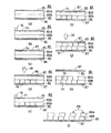
図30(a)〜(d)は、それぞれ、液晶マザー基板等の貼り合わせガラス基板を所望の裁断位置にて裁断する従来の手順の一例として、液晶マザー基板の第1の分断方法を、工程毎に説明する断面図である。なお、以下の説明では、便宜上、液晶マザー基板である一対のガラス基板を互いに対向して貼り合わせて形成される貼り合わせガラス基板71の一方側のガラス基板をガラス基板7A、他方側のガラス基板をガラス基板7Bとする。
30 (a) to 30 (d) show a first method for cutting a liquid crystal mother substrate as an example of a conventional procedure for cutting a laminated glass substrate such as a liquid crystal mother substrate at a desired cutting position. It is sectional drawing demonstrated for every. In the following description, for convenience, a glass substrate on one side of a
(1)まず、図30(a)に示すように、貼り合わせガラス基板71のガラス基板7Aを上側にして、貼り合わせガラス基板71を第1のスクライブ装置上に載置し、ガラス基板7Aに対して、ガラスカッターホイール72を用いてスクライブしてスクライブラインSaを形成する。
(1) First, as shown in FIG. 30A, the laminated
(2)次に、ガラス基板7AにスクライブラインSaを形成した貼り合わせガラス基板71の表裏を反転させて、第2のスクライブ装置に搬送する。そして、この第2のスクライブ装置にて、図30(b)に示すように、貼り合わせガラス基板71のガラス基板7Bに対して、ガラスカッターホイール72を用いてスクライブして、スクライブラインSbをスクライブラインSaに平行に形成する。なお、液晶マザー基板では、複数の液晶パネルが形成され、この各液晶パネルが形成される一方のガラス基板の側縁部上に端子を形成する必要があるために、ガラス基板7Bに形成されるスクライブラインSbは、ガラス基板7Aに形成されたスクライブラインSaと、水平方向にスクライブ位置が互いにずれるように形成されることが多い。
(2) Next, the front and back of the laminated
(3)次に、ガラス基板7A及びガラス基板7BのそれぞれにスクライブラインSa及びSbが形成された貼り合わせガラス基板71を、ガラス基板7A及びガラス基板7Bの上下を反転させることなく、ガラス基板7Bを上側にして、第1のブレイク装置に搬送する。この第1のブレイク装置では、図30(c)に示すように、貼り合わせガラス基板71は、マット74上に載置され、貼り合わせガラス基板71のガラス基板7Bに対して、ブレイクバー73がガラス基板7Aに形成されたスクライブラインSaに沿って押し付けられる。これにより、下側のガラス基板7Bは、スクライブラインSaから上方に向かって垂直クラックが伸長し、ガラス基板7Aは、スクライブラインSaに沿ってブレイクされる。
(3) Next, the laminated
(4)次に、ガラス基板7Aがブレイクされた貼り合わせガラス基板71を、ガラス基板7A及びガラス基板7Bの上下を反転させて、ガラス基板7Aを上側にして、第2のブレイク装置に搬送する。この第2のブレイク装置では、図30(d)に示すように、貼り合わせガラス基板71は、マット74上に載置され、貼り合わせガラス基板71のガラス基板7Aに対して、ブレイクバー73がガラス基板7Bに形成されたスクライブラインSbに沿って押し付けられる。これにより、下側のガラス基板7Bは、スクライプラインSbに沿ってブレイクされる。
(4) Next, the laminated
上記(1)〜(4)の各工程を実施することにより、貼り合わせガラス基板71は、所望の位置にて2つに分断される。
By performing each process of said (1)-(4), the
上記の工程(3)及び(4)で示されているように、上側に位置するガラス板にブレイクバー73が押し付けられることによって、下側のガラス基板がブレイクされる。例えば、図30(c)に示すように、上側のガラス基板7Bに、プレクバー73を押し付けると、ガラス基板7A及びガラス基板7Bは、ブレイクパー73の押し付けられた部分が下方に撓んだ状態になり、ガラス基板7Aに生じていたスクライブラインSaの垂直方向の亀裂(垂直クラック)を両側へ広げる向きに力が加わる。これにより、その垂直クラックが上方に伸長して、ガラス基板7Aの上部に達することにより、ガラス基板7Aが分断される。一方、上側のガラス基板7Bに形成されたスクライブラインSbには、下側のガラス基板の場合と反対に、亀裂(垂直クラック)を両側から抑え込む力が作用するため、上側のガラス基板7Bはブレイクされない。
As shown in the above steps (3) and (4), the lower glass substrate is broken by pressing the
工程(3)及び(4)にて実施されるブレイク工程において、例えば、図30(c)に示すように、下面側のガラス基板7AのスクライブラインSaでの垂直クラックの深さが浅いと、ガラス基板7Aをブレイクするために比較的大きな押し付け力を加えることが必要となる。しかしながら、ブレイクバー73による押し付け力が強過ぎる場合には、上側のガラス基板7Bが同時にブレイクされるおそれがある。この場合、下側のガラス基板7Aでは、垂直クラックがほぼ垂直方向に延びてブレイクが進むため問題を生じないが、上側のガラス基板7Bでは、ブレイクバー73により押し付ける力が加えられる位置と、ガラス基板7Bに形成されたスクライブラインSbの位置とが異なっており、上側のガラス基板7Bをブレイクするような向きの力が作用しないため、斜め方向の分断面が形成されるおそれがある。また、亀裂の部分が互いに衝突して、その箇所に欠け(水平クラック)が生じるおそれもある。このような斜め方向の分断面、欠け等が発生した貼り合わせガラス基板は、液晶パネルとしての商品価値が消失する。
In the breaking step performed in the steps (3) and (4), for example, as shown in FIG. 30 (c), if the depth of the vertical crack in the scribe line Sa of the
そこで、本願出願人は、特許文献1の「貼り合わせガラス基板の裁断方法」にて、このような問題を解決することのできる脆性基板の分断方法を提案した。
In view of this, the applicant of the present application has proposed a method for cutting a brittle substrate that can solve such a problem in “Cut method for bonded glass substrate” in
図31(a)〜(d)は、それぞれ、この特許文献1に記載された脆性材料を分断する第2の分断方法について、工程毎に説明する断面図である。以下、図31(a)〜(d)に基づいて、この特許文献1に記載された方法について説明する。
FIGS. 31A to 31D are cross-sectional views illustrating the second dividing method for dividing the brittle material described in
なお、以下の説明では、上記図30(a)〜(d)と同様、便宜上、液晶マザー基板である一対のガラス基板を互いに対向して貼り合わせて形成される貼り合わせガラス基板71の一方側のガラス基板をガラス基板7A、他方側のガラス基板をガラス基板7Bとする。
In the following description, as in FIGS. 30A to 30D, for convenience, one side of a bonded
(1)まず、図31(a)に示すように、貼り合わせガラス基板71のガラス基板7Aを上側にして、第1のスクライブ装置上に載置し、ガラス基板7Aに対して、ガラスカッターホイール72を用いてスクライブラインSaを形成する。
(1) First, as shown in FIG. 31 (a), the
(2)次に、ガラス基板7AにスクライブラインSaを形成した貼り合わせガラス基板71の表裏を反転させて、第1のブレイク装置に搬送する。この第1のブレイク装置では、図31(b)に示すように、貼り合わせガラス基板71は、マット74上に載置され、貼り合わせガラス基板71のガラス基板7Bに対して、ブレイクバー73がガラス基板7Aに形成されたスクライブラインSaに沿って押し付けられる。これにより、下側のガラス基板7Aでは、スクライブラインSaから上方に向かって垂直クラックが伸長し、ガラス基板7AはスクライブラインSaに沿ってブレイクされる。
(2) Next, the front and back of the
(3)次に、ガラス基板7Aがブレイクされた貼り合わせガラス基板71を、ガラス基板7A及びガラス基板7Bの表裏を反転させることなく、第2のスクライブ装置に搬送する。そして、この第2のスクライブ装置にて、図31(c)に示すように、貼り合わせガラス基板71のガラス基板7Bに対して、ガラスカッターホイール72を用いてスクライブして、スクライブラインSbをスクライブラインSaに平行に形成する。なお、液晶マザー基板では、複数の液晶パネルが形成され、この各液晶パネルが形成される一方のガラス基板の側縁部上に端子を形成する必要があるために、ガラス基板7Bに形成されるスクライブラインSbは、ガラス基板7Aに形成されたスクライブラインSaと、水平方向にスクライブ位置が互いにずれるように形成されることが多い。
(3) Next, the bonded
(4)次に、その貼り合わせガラス基板71の表裏を反転させて、ガラス基板7Aを上側にして、第2のブレイク装置へ搬送する。この第2のブレイク装置では、図31(d)に示すように、貼り合わせガラス基板71は、マット74上に載置され、貼り合わせガラス基板71のガラス基板7Aに対して、ガラス基板7Bに形成されたスクライブラインSbの対向する部分に、ブレイクバー73をスクライブラインSbに沿って押し付ける。これにより、下側のガラス基板7Bは、スクライブラインSbに沿ってブレイクされる。上記(1)〜(4)の各工程を実施することにより、貼り合わせガラス基板71は、所望の位置にて分断される。
(4) Next, the front and back surfaces of the bonded
この脆性材料の第2の分断方法では、工程(2)及び(4)に示されるように、ブレイク工程時には、ブレイク対象となる下側のガラス基板にはスクライブラインが形成されているが、上側のガラス基板にはスクライブラインが存在しないため、下側のガラス基板と同時に、上側のガラス基板がブレイクされることはない。このため、前述の図30(a)〜(d)にて示す第1の分断方法で問題となっている斜め方向の分断面、欠け等が発生するおそれは解消される。 In this second method for cutting a brittle material, as shown in steps (2) and (4), a scribe line is formed on the lower glass substrate to be broken at the time of the breaking step. Since there is no scribe line in the glass substrate, the upper glass substrate is not broken simultaneously with the lower glass substrate. For this reason, the possibility of the occurrence of the oblique section, chipping, etc., which is a problem in the first cutting method shown in FIGS. 30 (a) to 30 (d), is solved.
図7には、この第1及び第2の分断方法に使用されるガラスカッターホイール72の回転軸に直交する方向から見た正面図を示している。このガラスカッターホイール72は、ホイール径φ、ホイール厚Wのディスク状とされ、ホイールの周囲に鈍角の刃先角αの刃先が形成されている。
In FIG. 7, the front view seen from the direction orthogonal to the rotating shaft of the
本願出願人は、特許文献2の「ガラスカッターホイール」にて、上記図7に示されるガラスカッターホイール72を改良して、更に、深い垂直クラックを形成することのできるガラスカッターホイールを開示している。
The applicant of the present application discloses a glass cutter wheel that can improve the
図29(a)及び(b)は、それぞれこの特許文献2に記載のガラスカッターホイールの正面図及び回転軸に沿う方向から見た側面図を示している。
29 (a) and 29 (b) show a front view of a glass cutter wheel described in
このガラスカッターホイール25は、ホイールの周囲に形成された刃先の稜線部に凹凸を形成している。即ち、刃先の稜線部25aに、U字状もしくはV字状の溝25bが形成されている。この溝25bは、刃先の稜線部25aから深さhに、ピッチP毎に切り欠くことにより形成されている。このような溝25bが形成されていることにより、高さhの突起jがピッチPの間隔毎に形成された形状を有している。
The
また、図29(a),(b)では、ガラスカッターホイールの稜線部に形成される溝を分かり易くするために、溝を大きくして描いているが、実際には、この溝は、肉眼で見ることができないミクロンオーダーのサイズである。 In FIGS. 29 (a) and 29 (b), the groove formed in the ridge line portion of the glass cutter wheel is drawn to make it easier to understand, but in actuality, this groove is not visible to the naked eye. It is a micron-order size that cannot be seen with.
下記の表1には、ホイール径φ、ホイール厚W等の具体的な数値を示しており、一例として,タイプ1とタイプ2の2種類を示している。
Table 1 below shows specific numerical values such as wheel diameter φ, wheel thickness W, etc., and two types of

ところが、上記した稜線部に凹凸が形成されたガラスカッターホイールは、従来のガラスカッターホイールに比較して、スクライブ性能を大幅に向上させることができるが、稜線部の全周にわたって、精密な凹凸を形成したものであるため、稜線部に凹凸を加工形成するために、長時間を要し、加工性に問題を有している。また、上記のような、稜線部に凹凸が形成されたガラスカッターホイール25を用いて、図31に示す第2の分断方法を行うと、工程(3)において、上側のガラス基板7Bをスクライブした時点で、このガラス基板7Bに深い垂直クラックのスクライブラインSbが形成されて、実質的に、貼り合わせガラス基板71が分断された状態になる場合がある。そのため、工程(3)から工程(4)に移行するために、貼り合わせガラス基板71を、吸引パッド等で吸引して第2のブレイク装置に搬送する際に、分断された貼り合わせガラス基板71の一部分が、第2のスクライブ装置に残される場合があり、さらには、貼り合わせガラス基板71の搬送中に、分断された貼り合わせガラス基板71の一部分が落下する場合があり、貼り合わせガラス基板71を分断するライン装置が正常に作動しなくなるおそれがある。
However, the glass cutter wheel with irregularities formed on the ridgeline described above can greatly improve the scribing performance compared with the conventional glass cutter wheel, but it has precise irregularities over the entire circumference of the ridgeline part. Since it is formed, it takes a long time to process the concavo-convex portions in the ridge line portion, and there is a problem in workability. Moreover, when the 2nd parting method shown in FIG. 31 was performed using the
更に、こうした一連の分断工程では、スクライブ装置が用いられ、0.6〜2mm程度の厚みを有するダイヤモンド製のカッターホイールによって、上記のように、それぞれの基板の表面をスクライブして基板の厚み方向に垂直クラックを発生させ、適宜ブレイクして垂直クラックを伸展させて、分断を行っている。このスクライブ工程においては、切り屑(カレット)が多少に拘らず必然的に発生する。この貼り合わせ基板は、こうしたカレットが残存すると、貼り合わせ基板にキズがつき、貼り合わせ基板の品質を損ねる原因となる。このため、カレットの除去作業を適宜行うことが必要である。 Furthermore, in such a series of cutting steps, a scribing device is used, and the surface of each substrate is scribed by a diamond cutter wheel having a thickness of about 0.6 to 2 mm as described above in the thickness direction of the substrate. The vertical cracks are generated in the cracks, and the breaks are made as appropriate to extend the vertical cracks. In this scribing process, chips (cullet) are inevitably generated regardless of the amount. In the bonded substrate, when such cullet remains, the bonded substrate is scratched, and the quality of the bonded substrate is deteriorated. For this reason, it is necessary to appropriately perform cullet removal work.
ところが、スクライブ時に発生したカレットの除去作業は、手間がかかり、しかも完全に除去することが困難な場合もある。また、このカレットの除去によりガラス基板表面にキズがつくという問題がある。このキズは液晶表示ガラス基板においても好ましいものではないが、とりわけプロジェクター基板においては、キズが微小なものであっても、投影するとそのキズが拡大され、プロジェクター基板としての品質は低下し、信頼性を確保できず、歩留りは低下する。 However, the work of removing the cullet generated at the time of scribing takes time and may be difficult to remove completely. Further, there is a problem that the glass substrate surface is scratched by the removal of the cullet. Although this scratch is not preferable even in a liquid crystal display glass substrate, even in the case of a projector substrate, even if the scratch is minute, the scratch is enlarged when projected, the quality as a projector substrate is lowered, and reliability Cannot be secured, and the yield decreases.
本発明は、以上の従来の問題点を解決するためになされたものであり、貼り合わせ基板、とりわけプロジェクター基板の分断工程において発生するカレットによって表面にキズがつくことを回避することができ、品質のよい貼り合わせ基板を提供するとともに、貼り合わせ基板を分断するのに十分な垂直クラックを得て、スクライブラインに沿った精確な分断を行なうことができる貼り合わせ基板の分断方法を提供する。 The present invention has been made in order to solve the above-described conventional problems, and can prevent the surface from being scratched by a cullet generated in the cutting process of a bonded substrate, particularly a projector substrate. In addition to providing a good bonded substrate, there is provided a method for dividing a bonded substrate capable of obtaining a vertical crack sufficient to divide the bonded substrate and performing accurate dividing along a scribe line.
本発明の請求項1に対応する発明の貼り合わせ基板の分断方法(発明1)は、一対のガラス基板を対向して貼り合わせた貼り合わせ基板を分断する方法であって、当該貼り合わせ基板の両面に薄いフィルムを貼り付けた状態で、当該薄いフィルムの上からカッターホイールを用いてガラス基板にスクライブを行う工程と、前記スクライブ工程後、スクライブされた前記ガラス基板上の前記薄いフィルム上に、当該薄いフィルムより厚みが大きく、かつ、粘着力の強い保護フィルムを貼り付け、その後、当該保護フィルムを、前記薄いフィルムとともにスクライブされたガラス基板から剥離させる工程を有することを特徴とするものである。 The method for dividing a bonded substrate of the invention corresponding to claim 1 of the present invention (Invention 1) is a method of dividing a bonded substrate in which a pair of glass substrates are bonded to each other. In a state where a thin film is attached to both surfaces, a step of scribing a glass substrate using a cutter wheel from above the thin film, and after the scribing step, on the thin film on the scribed glass substrate, It is characterized by having a step of attaching a protective film having a thickness larger than that of the thin film and having a strong adhesive force, and then peeling the protective film from the glass substrate scribed together with the thin film. .
以上の構成により、スクライブ工程において発生するカレットはガラス基板に付着しない。 With the above configuration, the cullet generated in the scribe process does not adhere to the glass substrate.
この構成において、スクライブ工程時に発生したカレットは、保護フィルムに密着し、この保護フィルムを剥がす際に薄いフィルムとともに除去される。 In this configuration, the cullet generated during the scribing process adheres to the protective film, and is removed together with the thin film when the protective film is peeled off.
また、上記構成において、上記貼り合わせ基板の両面に薄いフィルムを貼り付けた後、下層のガラス基板側の前記薄いフィルム上にこのフィルムより厚みが大きく、かつ、粘着力の弱い第1の保護フィルムを貼り付けた状態で、上層のガラス基板側の薄いフィルム面側からスクライブすることにより、当該上層のガラス基板に、垂直クラックを形成し、その後、その上層のガラス基板上の薄いフィルム上に、当該薄いフィルムより厚みが大きく、かつ、粘着力の強い第2の保護フィルムを貼り付けるとともに、当該第2の保護フィルムが貼り付けられた前記上層のガラス基板が下層側に、前記第1の保護フィルムが貼り付けられた下層のガラス基板が上層側になるように、前記貼り合わせ基板を反転させ、第1の保護フィルムを剥がした後、上層に位置させたガラス基板をその薄いフィルム面側からスクライブすることにより、当該上層に位置させたガラス基板に垂直クラックを形成し、その後、その上層に位置させたガラス基板上の薄いフィルム上に当該薄いフィルムより厚みが大きく、且つ、粘着力の強い第2の保護フィルムをさらに貼り付けた後、上層及び下層のガラス基板にそれぞれ貼り付けられた第2の保護フィルムを、薄いフィルムとともに上層及び下層のガラス基板から剥離させるように構成してもよい。 Moreover, in the said structure, after sticking a thin film on both surfaces of the said bonding board | substrate, the thickness is larger than this film on the said thin film of the lower glass substrate side, and a 1st protective film with weak adhesive force in a state of paste, by scribing a thin film surface side of the upper layer of the glass substrate side, to the upper layer of the glass substrate, forming a vertical crack, then a thin have on the film on the glass substrate of the upper layer A second protective film having a thickness larger than that of the thin film and having a strong adhesive force is attached to the upper glass substrate to which the second protective film is attached on the lower layer side. After the first protective film is peeled off by inverting the bonded substrate so that the lower glass substrate to which the protective film is attached is on the upper layer side, By scribing the glass substrate positioned in the layer from the thin film surface side, a vertical crack is formed in the glass substrate positioned in the upper layer, and then on the thin film on the glass substrate positioned in the upper layer. After the second protective film having a thickness larger than that of the thin film and having a strong adhesive force is further attached, the second protective film attached to the upper layer and the lower glass substrate, together with the thin film, You may comprise so that it may peel from a lower glass substrate.
この構成では、上記の構成同様、スクライブ工程時にカレットが生じてもガラス基板に付着せず、ガラス基板をキズつけない。また、下側となるガラス基板に貼り付けられた第1及び第2の保護フィルムにより、スクライブ時においてスクライブテーブルとの直接接触から貼り合わせ基板を有効に保護する。最終的に第2の保護フィルムを剥がすことにより、薄いフィルムもともにガラス基板から剥がれるので、ガラス基板上に残存するカレットが第2の保護フィルムとともに除去され、清浄なガラス基板面を確保できる。 In this configuration, as in the above configuration, even if cullet is generated during the scribing process, it does not adhere to the glass substrate and the glass substrate is not damaged. In addition, the first and second protective films attached to the lower glass substrate effectively protect the bonded substrate from direct contact with the scribe table during scribing. By finally peeling off the second protective film, both thin films are peeled off from the glass substrate, so that the cullet remaining on the glass substrate is removed together with the second protective film, and a clean glass substrate surface can be secured.
本発明の請求項3に対応する発明の貼り合わせ基板の分断方法(発明2)は、ガラス基板とシリコン基板とを対向して貼り合わせた貼り合わせ基板を分断する方法であって、前記ガラス基板に薄いフィルムを貼り付けた状態で、当該薄いフィルムの上からカッターホイールを用いてガラス基板にスクライブを行なう工程と、前記スクライブ工程後、前記ガラス基板上の前記薄いフィルム上に、当該薄いフィルムより厚みが大きく、かつ、粘着力の強い保護フィルムを貼り付け、その後、その保護フィルムを、薄いフィルムとともに前記ガラス基板から剥離させる工程を有することによって特徴付けられる。 A method for dividing a bonded substrate according to a third aspect of the present invention (Invention 2) is a method for dividing a bonded substrate in which a glass substrate and a silicon substrate are bonded to each other, the glass substrate In a state where a thin film is attached to the glass substrate, a step of scribing the glass substrate from above the thin film using a cutter wheel, and after the scribing step, on the thin film on the glass substrate, from the thin film It is characterized by having a step of attaching a protective film having a large thickness and strong adhesive force, and then peeling the protective film together with the thin film from the glass substrate .
以上の構成により、発明2は、発明1同様、スクライブ工程において発生するカレットはガラス基板に付着しない。
With the above configuration, the
この構成では、スクライブ工程時に発生したカレットは、保護フィルムに密着し、この保護フィルムを剥がす際に薄いフィルムとともに除去される。 In this configuration, the cullet generated during the scribing process adheres to the protective film and is removed together with the thin film when the protective film is peeled off.
上記構成において、前記ガラス基板上に薄いフィルムを貼り付けた後、前記シリコン基板を下層に位置させた状態で、上層のガラス基板側の薄いフィルム面側からスクライブすることにより、当該上層のガラス基板の下面に到る垂直クラックを形成し、その後、その上層のガラス基板上の前記薄いフィルム上に、当該薄いフィルムより厚みが大きく、かつ、粘着力の強い保護フィルムを貼り付けるとともに、前記下層のシリコン基板が上層側になるように、当該貼り合わせ基板を反転させ、上層に位置させたシリコン基板をスクライブした後、このシリコン基板が下層側になるように、当該貼り合わせ基板を反転させ、上層に位置させたガラス基板側を加圧することにより、シリコン基板に垂直クラックを形成するように構成してもよい。 In the above configuration, after attaching a thin film on the glass substrate, in a state of being positioned with the silicon substrate in the lower layer, by scribing a thin film surface side of the upper layer of the glass substrate, the upper glass substrate of the vertical crack formed leading to the lower surface, then the thin film on the glass substrate of the upper layer, large thickness than the thin film, and, together with the paste strong protective film of adhesive strength, the lower layer The bonded substrate is inverted so that the silicon substrate is on the upper layer side, and after scribing the silicon substrate positioned on the upper layer, the bonded substrate is inverted so that the silicon substrate is on the lower layer side. A vertical crack may be formed in the silicon substrate by pressurizing the glass substrate side positioned in the silicon substrate.
この構成では、貼り合わせ基板を構成する一方の基板はシリコン基板を用いているので、スクライブによるカレットの発生による影響を受けない。もう一方のガラス基板にのみ、薄いフィルムを貼り付け、この状態でスクライブするので、スクライブ工程時にカレットが生じてもガラス基板に付着せず、ガラス基板をキズつけない。さらに、カレットを除去するために保護フィルムを貼り付け、この保護フィルムを剥がすと、薄いフィルムとともにガラス基板から剥がれるので、カレットを保護できる。
In this configuration, since one substrate constituting the bonded substrate is a silicon substrate, it is not affected by the occurrence of cullet due to scribing. Since a thin film is attached only to the other glass substrate and scribed in this state, even if cullet is generated during the scribing process, it does not adhere to the glass substrate and the glass substrate is not scratched. Further, when a protective film is attached to remove the cullet and the protective film is peeled off, the cullet can be protected because it peels off from the glass substrate together with the thin film .
また、以上の構成において、上記スクライブを行う手段として、カッターホイールを用いるとともに、このカッターホイールは、その刃先稜線部が全周にわたって溝が形成された第1のカッターホイール、あるいは、溝が形成された領域と、溝が形成されていない領域が所定の割合で形成された第2のカッターホイールを選択的に用いてもよい。 Further, in the above configuration, a cutter wheel is used as the means for performing the scribing, and the cutter wheel is formed with a first cutter wheel having a groove formed on the entire edge of the blade edge line or a groove. The second cutter wheel in which the region and the region where no groove is formed is formed at a predetermined ratio may be selectively used.
これらのカッターホイールを用いることにより、脆性材料の基板の分断が可能となる。さらに第1のカッターホイールを用いた場合、ガラス基板下面に到る垂直クラックが得られる。一方、第2のカッターホイールを用いた場合、周期的に深さが変化する垂直クラックが得られる。 By using these cutter wheels, the substrate of the brittle material can be divided. Furthermore, when the 1st cutter wheel is used, the vertical crack which reaches the glass substrate lower surface is obtained. On the other hand, when the second cutter wheel is used, a vertical crack whose depth periodically changes is obtained.
以下、本発明の実施の形態について図を参照して説明する。 Hereinafter, embodiments of the present invention will be described with reference to the drawings.
図1は、本実施の形態に適用されるカッターホイールの正面図、図15は、図1に示すカッターホイールによるスクライビングの状態を示す正面図である。 FIG. 1 is a front view of a cutter wheel applied to the present embodiment, and FIG. 15 is a front view showing a scribing state by the cutter wheel shown in FIG.
このカッターホイール1は、刃先稜線2が、ホイールの両側面3,4間の中心5よりいずれか一方の側面(図示例では左側面3)寄りに偏位されるとともに、ホイールの中心に挿通孔6が形成されたものである。刃先稜線2の偏位度合いが大きい程、つまり中心5から刃先稜線2までの距離が長くなる程、換言すると図示例では左側面3と刃先稜線2との距離が短くなる程、図15に示すように、スクライビングの際に素子の凸部や薄膜Xにより近づいてスクライブすることができるので好ましい。このようになるカッターホイール1の大きさとしては、例えば、ホイールの厚みwが0.65mm、刃先稜線2における直径φが2〜3mm、ホイールの左側面3から刃先稜線2までの距離kが30〜150μm、挿通孔6の内径dが0.8mmとされるが、この大きさに限定されるものではない。なお、図15において符号Gは脆性基板を示す。
The
上記のようになるカッターホイール1で脆性材料基板Gのスクライビングを行うには、図15に示すように、カッターホイール1を、刃先稜線2が寄っている方の側面が素子の凸部や薄膜Xに臨むようにして脆性材料基板Gにあてがわれる。ここで、素子Xは脆性材料基板G上にマトリックス状に配列されているので、一方の列の素子に沿ってそれらの凸部や薄膜Xの直近をスクライブし、1本のスクライブラインEを形成したならば、次にカッターホイール1を180度反転して、先の列に隣接する列の素子に沿ってそれらの凸部や薄膜Xの直近をスクライブし、次のスクライブラインFを形成する。
In order to perform scribing of the brittle material substrate G with the
スクライビングに際しては、このように、1本のスクライブラインの形成を完了する毎にカッターホイール1を180度反転させる他に、2個のカッターホイール1,1を、図15に示すような関係となるよう、すなわち2個のカッターホイール1,1が並列に、且つ、相互の刃先稜線2,2が最も離れた位置となるよう配されたチップホルダー(図示省略)を使用してもよい。このように2個のカッターホイール1,1を用いた場合は、スクライブヘッドを各素子間に1回走らせるだけで、隣接する各素子の凸部や薄膜X,Xにそれぞれ近接した箇所E,Fを同時にスクライブすることが可能となり、上記のように1本のスクライブラインが形成される毎にカッターホイール1を180度反転させる必要がなくなり、作業性が向上する。また、2個のカッターホイール1,1は、動作プログラムにより、選択的に、同時または個別にスクライブすることができるようになっている。
At the time of scribing, in addition to reversing the
次に、図2(a)は、刃先稜線に突起を形成したカッターホイールの正面図である。また、図2(b)は同ホイールの部分拡大図を伴う側面図である。ここでは、カッターホイール11の刃先稜線21に、拡大図Aに示すように、U字形状の溝71を切り欠くことで、高さhの突起81をピッチPの間隔で得ている。
Next, Fig.2 (a) is a front view of the cutter wheel which formed the processus | protrusion in the blade edge ridgeline. Moreover, FIG.2 (b) is a side view with the elements on larger scale of the wheel. Here, as shown in the enlarged view A in the cutting
ここで例示したホイール11は、ホイール径(φ) が2. 5mm、ホイール厚(w) が0. 65mm、刃先角度(α) が125°、突起数が125個、突起の高さ(h) が5μm、ピッチ(P) が63μmであり、このガラスカッターホイール11を用い、刃先荷重2. 6Kgf、スクライブ速度300mm/secの条件で1. 1mm厚のガラス板をスクライブした時のガラス断面を図16に示している。
The
図16において、ガラス板Gの上面にあるくぼみLがスクライブ時に生じたガラスの溝であり、これをスクライブラインと称している(このラインは紙面に対し垂直方向に延在する) 。このスクライブラインLの刻設と同時に、このスクライブラインLから直下方向に延びるクラック(垂直クラック) Kが発生するが、この場合、ガラス板Gを板厚方向にほぼ貫通するような長いクラック(実測962μm) が発生している。 In FIG. 16, a recess L on the upper surface of the glass plate G is a glass groove formed during scribing, and this is called a scribe line (this line extends in a direction perpendicular to the paper surface). Simultaneously with the engraving of the scribe line L, a crack (vertical crack) K is generated extending downward from the scribe line L. In this case, a long crack (actually measured through the glass plate G in the thickness direction) is generated. 962 μm).
このように、突起81を設けたカッターホイール11は、刃先荷重を大きくしても、水平クラックの発生はなく、その荷重の大きさに比例する深さで長い垂直クラックKが得られる。この垂直クラックKが長いと、次工程のブレイク作業において、スクライブラインに沿った精確なブレイクが行え、歩留りが向上する。又、ブレイク作業が容易なことから、ブレイク工程の内容を緩和あるいは簡素化でき、場合によってはブレイク工程を省略することも可能となる。
As described above, the
図3は、上記とは異なる形状を有する突起82の例を示しており、刃先稜線22にV字形状の溝72を切り欠くことで突起82を形成している。
FIG. 3 shows an example of the
図4は、さらに上記とは異なる形状を有する突起83の例を示しており、刃先稜線23に鋸形状の溝73を切り欠くことで突起83を形成している。
FIG. 4 further shows an example of the
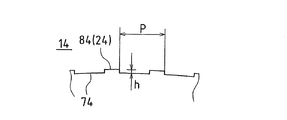
図5は、またさらに上記とは異なる形状を有する突起84の例を示しており、刃先稜線24に矩形の溝74を切り欠くことで突起84を形成している。
FIG. 5 shows an example of the
上述のカッターホイール1は、挿通孔6を有しており、この挿通孔6に軸(図示省略)を挿通して図示しないスクライブヘッドのチップホルダに装着されるが、図6に示すように、ホイールの両側面3,4に軸9をホイールと一体的に突設してもよい。
The
この場合、軸管理が容易となる。すなわち、カッターホイール1の使用に際しては、カッターホイール1の中心に設けられた挿通孔6に軸を挿通するが、ホイール径は数ミリメートルと小さく、それ故、軸の径は1ミリメートル以下となることもある。このように、微小な軸の管理は煩雑であるところ、軸9がホイールと一体であれば、軸管理が容易となるのである。
In this case, axis management becomes easy. That is, when the
図8は、本実施の形態に適用されるカッターホイール16を示す側面図である。
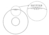
このカッターホイール16は、図8に示すように、刃先稜線部を溝が形成された領域Aと溝が形成されていない領域Bとを有するものとしている。このような溝が形成された領域Aの稜線部の全周(A領域十B領域)に対する比率(以下、全周に対する領域Aの比率と称する)は、カッターホイール16の稜線に溝を形成する加工性を考慮すると、3/4以下であることが好ましい。このような比率であれば、溝を形成するための加工に長時間を要することがなく、加工性に優れたものとすることができる。
FIG. 8 is a side view showing the
As shown in FIG. 8, the
また、全周に対する領域Aの比率3/4以下であって、1/4より大きい範囲であると、後述の図23に示すような、周期的に深さが変化する垂直クラックが得られる。ただし、全周に対する領域Aの比率がこのような範囲である場合には、上記の周期的なクラックを得るためには、限られた条件にすることが必要になる。 Further, when the ratio of the area A to the entire circumference is 3/4 or less and is in a range larger than 1/4, a vertical crack whose depth periodically changes as shown in FIG. 23 described later is obtained. However, when the ratio of the area A to the entire circumference is in such a range, it is necessary to set a limited condition in order to obtain the above-described periodic cracks.
これに対して、全周に対する領域Aの比率が1/4以下の範囲にすると、広い条件で安定して周期的に深さが変化する垂直クラックが得られる。全周に対する領域Aの比率が、この範囲に設定されていると、スクライブラインを形成した脆性基板を搬送する場合に、搬送途中で脆性材料基板の一部分が分断して落下する等の問題が生じることを防ぐために適している。 On the other hand, when the ratio of the area A to the entire circumference is set to a range of ¼ or less, a vertical crack whose depth is stably and periodically changed under a wide condition can be obtained. When the ratio of the area A to the entire circumference is set within this range, when a brittle substrate having a scribe line formed is conveyed, there arises a problem that a portion of the brittle material substrate is divided and dropped during the conveyance. Suitable to prevent that.
稜線部のA領域に形成される溝6bは、ミクロンオーダーで意図的に周期的に加工されたものであり、刃先稜線を形成する研削加工の際に、必然的に形成されるサブミクロンオーダーの研磨条痕とは区別される。
The
図9は、他の実施の形態のガラスカッターホイールの例を示しており、図9(a)は、刃先全周を6領域に区分して、領域Aと領域Bとが交互に形成されるように設定したものである。図9(b)は、刃先全周を8領域に区分して、領域Aと領域Bとを交互に形成されるように設定したものである。 FIG. 9 shows an example of a glass cutter wheel according to another embodiment, and FIG. 9A divides the entire periphery of the cutting edge into six regions, and regions A and regions B are alternately formed. It is set as follows. FIG. 9B is a diagram in which the entire periphery of the cutting edge is divided into eight regions, and regions A and regions B are alternately formed.
図9(b)では、溝が形成された領域AがA1〜A4の複数の領域にわたって形成され、溝が形成されていない領域BがB1〜B4の複数の領域にわたって形成されている。各領域A1〜A4及びB1〜B4の長さは、例えば、
A1=A2=A3=A4 A1+A2十A3十A4=A
B1=B2=B3=B4 B1+B2+B3+B4=B
A/B=1
となるように設定される。この場合、各領域A1〜A4が全て等しく、また、B1〜B4が全て等しくなっている。また、A/B=1となっているので、領域Aの全周に対する比率は、2/4となっている。
In FIG. 9B, a region A in which a groove is formed is formed over a plurality of regions A1 to A4, and a region B in which no groove is formed is formed over a plurality of regions B1 to B4. The length of each region A1 to A4 and B1 to B4 is, for example,
A1 = A2 = A3 = A4 A1 + A2 + A3 + A4 = A
B1 = B2 = B3 = B4 B1 + B2 + B3 + B4 = B
A / B = 1
Is set to be In this case, all the areas A1 to A4 are all equal, and B1 to B4 are all equal. Since A / B = 1, the ratio of the area A to the entire circumference is 2/4.
また、別の例では、
A1=A2≠A3≠A4 A1+A2十A3十A4=A
B1=B2≠B3≠B4 B1+B2+B3+B4=B
A/B=1
となるように設定される。この場合、各領域A1〜A4及びB1〜B4で、A3及びA4が、A1及びA2と異なっており、また、B3及びB4が、B1及びB2と異なっている。また、全体として、A/B=1となっているので、領域Aの全周に対する比率は、2/4となっている。
In another example,
A1 = A2 ≠ A3 ≠ A4 A1 + A2 + A3 + A4 = A
B1 = B2 ≠ B3 ≠ B4 B1 + B2 + B3 + B4 = B
A / B = 1
Is set to be In this case, in each of the regions A1 to A4 and B1 to B4, A3 and A4 are different from A1 and A2, and B3 and B4 are different from B1 and B2. Moreover, since A / B = 1 as a whole, the ratio of the area A to the entire circumference is 2/4.
さらに他の例では、
A1=A2≠A3≠A4 A1+A2十A3十A4=A
B1=B2≠B3≠B4 B1+B2十B3十B4=B
A/B=3/1
となるように設定される。この場合、各領域A1〜A4及びB1〜B4で、A3及びA4が、A1及びA2と異なっており、また、B3及びB4が、B1及びB2と異なっている。また、全体として、A/B=3/1となっているので、領域Aの全周に対する比率は、3/4となっている。
In yet another example,
A1 = A2 ≠ A3 ≠ A4 A1 + A2 + A3 + A4 = A
B1 = B2 ≠ B3 ≠ B4 B1 + B2 + B3 + B4 = B
A / B = 3/1
Is set to be In this case, in each of the regions A1 to A4 and B1 to B4, A3 and A4 are different from A1 and A2, and B3 and B4 are different from B1 and B2. Further, since A / B = 3/1 as a whole, the ratio of the area A to the entire circumference is 3/4.
このカッターホイール16は、このホイール16に挿通される軸と一体的に形成されてもよい。一体的に形成する方法としては素材よりホイールと軸とを一体に研削加工する方法、刃先と軸とを接着および/またはろう付けする方法等が用いられる。
The
図23は、上記のカッターホイール16を用いてガラス基板にスクライブラインを形成した場合にガラス基板に発生する垂直クラックを概略的に示す模式図である。
FIG. 23 is a schematic diagram schematically showing a vertical crack generated in the glass substrate when a scribe line is formed on the glass substrate using the
カッターホイール16を用いたスクライブにより生じるスクライブラインは、カッターホイールの稜線部において、溝が形成されたA領域により形成されたスクライブラインSA と、溝が形成されていないB領域により形成されたスクライブラインSB とで、垂直クラックの深さが異なっており濃淡が確認された。即ち、スクライブラインSA では、稜線部に形成された凹凸により深い垂直クラックDA が形成され、スクライブラインSB では、稜線部に凹凸が形成されていないため、浅い垂直クラックDB が形成されることが確認された。
Scribe scribe line caused by scribing using a
このように、本実施形態のカッターホイール16を用いたスクライブでは、垂直クラックの深さが周期的に変化していることから、本実施の形態では、そのスクライブ性能は、図7の従来のカッターホイール72におけるスクライブ性能と図2のカッターホイール11におけるスクライブ性能との中間になることがわかる。さらに、カッターホイールの全周に対して、溝が形成された領域Aと溝が形成されていない領域Bとの比率を適宜変更することにより、所望のスクライブ特性を得ること、すなわち、ガラス基板を分断するための所望の垂直のクラックのライン(スクライブライン)が得られる。
Thus, in the scribe using the
以下、本実施の形態に適用されるカッターホイールの具体例I〜Vについて説明する。 Hereinafter, specific examples I to V of the cutter wheel applied to the present embodiment will be described.
(具体例I)
図10に、具体例Iのカッターホイールの形態を示し、下記の表2には、本具体例Iの
カッターホイールのホイール径等の寸法を示している。
( Specific example I )
In FIG. 10, the form of the cutter wheel of the specific example I is shown, and Table 2 below shows dimensions such as the wheel diameter of the cutter wheel of the specific example I.
割)の部分に一箇所、同じ深さの溝(7μm)が連続して形成されるように設定している。
このカッターホイール16を用いて、厚み0.7mmの無アルカリガラスに対して、刃先荷重0.16〜0.40MPa、スクライブ速度400mm/secとして、スクライブを行った。この具体例Iのカッターホイール16を用いたスクライブでは、図23に示
すように、垂直クラックの深さが周期的に変化するスクライブラインが形成され、0.18MPaの荷重を用いた場合、図23の深い垂直クラックDA は、約400μm、浅い垂直クラックDB は、約100μmとなった。
Using this
(具体例II)
図11に具体例IIのカッターホイール16の形態を示し、下記の表3には、本具体例II
のカッターホイールのホイール径等の寸法を示している。
( Specific example II )
FIG. 11 shows the configuration of the
The wheel diameter of the cutter wheel is shown.
割)の長さに、二箇所にわたって、同じ深さの溝(7μm)が連続して形成された領域A1及びA2を設けている。各溝が形成された領域、A1及びA2は、カッターホイール16の中心軸を挟んで反対側になるように設定されている。
このカッターホイール16を用いて、厚み0.7mmの無アルカリガラスに対して、刃先荷重0.16〜0.40MPa、スクライブ速度400mm/secとして、スクライブを行った。この具体例IIのカッターホイール16を用いたスクライブでは、図23に示すように、垂直クラックの深さが周期的に変化するスクライブラインが形成され、0.20MPaの荷重を用いた場合、図23の深い垂直クラックDA は、約400μm、浅い垂直クラックDB は、約100μmとなった。
Using this
(具体例III )
図12に具体例III のカッターホイール16の形態を示し、下記の表4には、本具体例IIIのカッターホイール16のホイール径等の寸法を示している。
( Specific example III )
FIG. 12 shows a configuration of the
このカッターホイール16を用いて、厚み0.7mmの無アルカリガラスに対して、刃先荷重0.16〜0.40MPa、スクライブ速度400mm/secとして、スクライブを行った。この具体例III のカッターホイール16を用いたスクライブでは、図23に示すように、垂直クラックの深さが周期的に変化するスクライブラインが形成され、0.20MPaの荷重を用いた場合、図23の深い垂直クラックDA は、約400μm、浅い垂直クラックDB は、約100μmとなった。
Using this
(具体例IV)
図13に具体例IVのカッターホイール16の形態を示し、下記の表5には、本具体例IVのカッターホイール16のホイール径等の寸法を示している。
( Specific example IV )
FIG. 13 shows the configuration of the
このカッターホイール16を用いて、厚み0.7mmの無アルカリガラスに対して、刃先荷重0. 16〜0.40MPa、スクライブ速度400mm/secとして、スクライブを行った。この具体例IVのガラスカッターホイール16を用いたスクライブでは、図23に示すように、垂直クラックの深さが周期的に変化するスクライブラインが形成され、0.22MPaの荷重を用いた場合、図23の深い垂直クラックDA は、約400μm、浅い垂直クラックDB は、約100μmとなった。
Using this
(具体例V)
図14に具体例Vのカッターホイール16の形態を示し、下記の表6には、本具体例V
のカッターホイール16のホイール径等の寸法を示している。
( Specific example V )
Figure 14 shows the form of the
The dimensions of the
て、3,5,7,7,7,5,3μmの深さの溝が、この順に形成されるように設定されている。
このカッターホイール16を用いて、厚み0.7mmの無アルカリガラスに対して、刃先荷重0.16〜0.40MPa、スクライブ速度400mm/secとして、スクライブを行った。この具体例Vのカッターホイールを用いたスクライブでは、図23に示すよ
うに、垂直クラックの深さが周期的に変化するスクライブラインが形成され、0. 29MPaの荷重を用いた場合、図23の深い垂直クラックDA は、約400μm、浅い垂直クラックDB は、約100μmとなった。
Using this
さらに、上記具体例I〜Vの結果により、複数個にわたって形成されている各溝のピッ
チは、1〜20mmのホイール径に応じて20〜200μmであることが好ましく、また、複数個の溝の深さは、1〜20mmのホイール径に応じて、2〜200μmであることが好ましいことが明らかになっている。
Further, according to the results of the above specific examples I to V , the pitch of each groove formed over a plurality is preferably 20 to 200 μm according to the wheel diameter of 1 to 20 mm. It has been found that the depth is preferably 2 to 200 μm, depending on the wheel diameter of 1 to 20 mm.
上記したカッターホイールの説明に用いた図においては、カッターホイールの稜線に形成される溝を分かり易くするために、溝を大きく描いているが、実際には、この溝は、肉眼で見ることができないミクロンオーダーのサイズである。
−スクライブ装置−
図17は、上記したカッターホイールを装着したスクライブ装置の一実施の形態を示す概略正面図である。
In the drawing used to describe the cutter wheel, the groove formed on the ridge line of the cutter wheel is drawn large in order to make it easy to understand, but in actuality, this groove can be seen with the naked eye. The micron order size is not possible.
-Scribe device-
FIG. 17 is a schematic front view showing an embodiment of a scribing device equipped with the cutter wheel described above.
図18は、図17のスクライブ装置の側面図である。 FIG. 18 is a side view of the scribing apparatus of FIG.
このスクライブ装置は、載置された脆性材料基板Gを真空吸着手段によって固定する水平回転可能なテーブル51と、このテーブル51をY方向(紙面に直交する方向)に移動可能に支承する平行な一対の案内レール52,52と、この案内レール52,52に沿ってテーブル51を移動させるボールネジ53と、X方向(この図における左右方向)に沿ってテーブル51の上方に架設されたガイドバー54と、このガイドバー54にX方向に摺動可能に設けられたスクライブヘッド55と、このスクライブヘッド55を摺動させるモータ56と、スクライブヘッド55の下部に昇降動可能且つ首振り自在に設けられたチップホルダ57と、このチップホルダ57の下端に回転可能に装着された上述のカッターホイール1と、ガイドバー54の上方に設置されテーブル51上の脆性材料基板Gに表示されたアラインメントマークを認識する一対のCCDカメラ58とを備えたものである。また、上記スクライブヘッド55内には、1本のスクライブラインの形成が完了する毎に前述の如くカッターホイール1を180度反転させるべくチップホルダ57を180度反転させるカッターホイール反転手段が内蔵されている。
This scribing apparatus includes a horizontally rotatable table 51 for fixing a placed brittle material substrate G by a vacuum suction means, and a pair of parallel supports for movably supporting the table 51 in the Y direction (direction perpendicular to the paper surface).
また、スクライブ装置は、上記したようなカッターホイール反転手段を設けずに、2個のチップホルダ57,57に2個のカッターホイール1,1を並列に、且つ、相互の刃先稜線2,2が最も離れた位置となるよう取り付けてもよい。このように2個のカッターホイール1,1を用いた場合は、スクライブヘッドを各素子間を1回走らせるだけで、隣接する各素子の凸部や薄膜X,Xにそれぞれ近接した箇所E,Fを同時にスクライブすることが可能(図15参照)となり、上記のように1本のスクライブラインが形成される毎にカッターホイール1を180度反転させる必要がなくなり、作業性が向上する。
Further, the scribing device does not include the cutter wheel reversing means as described above, and the two
さらに、2個のカッターホイール1,1は、動作プログラムにより、選択的に、同時または個別にスクライブすることができるようになっており、スクライブヘッド55には2個のチップホルダ57,57を個別に昇降させることができる昇降手段を内蔵している。
次に、本発明の実施形態に適用されるカッターホイールを備えた分断装置を用いて貼り合わせガラス基板を分断する方法について説明する。
Further, the two
Next, a method for cutting a laminated glass substrate using a cutting apparatus equipped with a cutter wheel applied to an embodiment of the present invention will be described.
図24(a)〜(c)は、それぞれ、本実施の形態に適用されるカッターホイールを備えた分断装置を用いて貼り合わせガラス基板10を分断する方法を、工程毎に説明する断面図である。なお、以下の説明では、便宜上、液晶マザー基板である一対のガラス基板を互いに対向して貼り合わせて形成される貼り合わせガラス基板の一方側のガラス基板をガラス基板10A、他方側のガラス基板をガラス基板10Bとする。
Figure 24 (a) ~ (c), respectively, a method of dividing the
(1)まず、図24(a)に示すように、貼り合わせガラス基板10のガラス基板10Aを上側にして、貼り合わせガラス基板10を第1のスクライブ装置上に載置し、ガラス基板10Aに対して、図1のカッターホイールの稜線に図2に示す溝を形成したカッターホイール11を用い、スクライブしてスクライブラインSa’を形成する。このガラスカッターホイール11を用いて形成されるスクライブラインSa’は、図24(b)に示すように、ガラス基板10Aの下面付近にまで到達するような深い垂直クラックVaが形成されている。
(1) First, as shown in FIG. 24 (a), the
(2)次に、ガラス基板10AにスクライブラインSa’を形成した貼り合わせガラス基板10の表裏を反転させて、第2のスクライブ装置に搬送する。そして、この第2のスクライブ装置にて、図24(b)に示すように、貼り合わせガラス基板10のガラス基板10Bに対して、図1のカッターホイール1の稜線に図8に示す溝を形成したカッターホイール16を用い、スクライブして、スクライブラインSa’に平行に、スクライブラインSb’を形成する。この第2のスクライブ装置は、具体例I〜Vのいずれかに記載され
たカッターホイールを使用しており、このカッターホイール16を用いて形成されるスクライブラインSb’は、浅く形成された部分と深く形成された部分が交互に周期的に変化する垂直クラックVbが形成される。なお、液晶マザー基板では、複数の液晶パネルが形成され、この各液晶パネルが形成される一方のガラス基板の側縁部上に端子を形成する必要があるために、ガラス基板10Bに形成されるスクライブラインSb’は、ガラス基板10Aに形成されたスクライブラインSa’と、水平方向にスクライブ位置が互いにずれるように形成されることが多い。
(2) Next, the front and back of the
(3)次に、ガラス基板10A及びガラス基板10BのそれぞれにスクライブラインSa’及びSb’が形成された貼り合わせガラス基板10を、ガラス基板10A及びガラス基板10Bの上下を反転させて、ガラス基板10Aを上側にして、ブレイク装置に搬送する。このブレイク装置では、図24(c)に示すように、貼り合わせガラス基板10は、マット44上に載置され、貼り合わせガラス基板10のガラス基板10Aに対して、ブレイクバー39をガラス基板10Bに形成されたスクライブラインSb’に沿って押し付ける。これにより、下側のガラス基板10Bは、スクライブラインSb’から上方に向かって垂直クラックが伸長し、ガラス基板10Bは、スクライブラインSb’に沿ってブレイクされる。
(3) Next, the
上記(1)〜(3)の工程を順次行うことにより、貼り合わせガラス基板10は分断される。
The
既述したようにカッターホイール16によるスクライブでは、浅く形成された部分と深く形成された部分が交互に周期的に変化する垂直クラックVbが形成され、垂直クラックVbがガラス基板の厚み方向に完全に貫通した状態とはならない。このため、上記の工程(2)において、第2のスクライブ装置からブレイク装置に、貼り合わせガラス基板10を搬送する途中で、ガラス基板10Aが完全に分断された状態になっていても、ガラス基板10Aが、ガラス基板10Bにシール剤で貼り合わされた状態になっているため貼り合わせガラス基板10が分離するおそれはない。
As described above, the scribing by the
図25(a)〜(d)は、それぞれ、本実施の形態に適用されるカッターホイール1を備えた分断装置を用いて貼り合わせガラス基板10を分断する第2の方法を工程毎に説明する断面図である。なお、以下の説明では、便宜上、液晶マザー基板である一対のガラス基板を互いに対向して貼り合わせて形成される貼り合わせガラス基板の一方側のガラス基板をガラス基板10A、他方側のガラス基板をガラス基板10Bとする。
Each of FIGS. 25A to 25D describes a second method for dividing the
(1)まず、図25(a)に示すように、貼り合わせガラス基板10のガラス基板10Aを上側にして、貼り合わせガラス基板10を第1のスクライブ装置上に載置し、ガラス基板10Aに対して、カッターホイール1(または15、16)を用いてスクライブしてスクライブラインScを形成する。
(1) First, as shown in FIG. 25A, the
(2)次に、ガラス基板10AにスクライブラインScを形成した貼り合わせガラス基板10の表裏を反転させて、第1のブレイク装置に搬送する。この第1のブレイク装置では、図25(b)に示すように、貼り合わせガラス基板10は、マット44上に載置され、貼り合わせガラス基板10のガラス基板10Bに対して、ブレイクバー39をガラス基板10Aに形成されたスクライブラインScに沿って押し付ける。これにより、下側のガラス基板10Aは、スクライブラインScから上方に向かって垂直クラックが伸長し、ガラス基板10Aは、スクライブラインScに沿ってブレイクされる。
(2) Next, the front and back of the bonded
(3)次に、ガラス基板10Aが分断された貼り合わせガラス基板10を、ガラス基板10A及びガラス基板10Bの表裏を反転させることなく、第2のスクライブ装置に搬送する。そして、この第2のスクライブ装置にて、図25(c)に示すように、貼り合わせガラス基板のガラス基板10Bに対して、カッターホイール16を用いてスクライブして、スクライブラインSdをスクライブラインScに平行に形成する。なお、液晶マザー基板では、複数の液晶パネルが形成され、この各液晶パネルが形成される一方のガラス基板の側縁部上に端子を形成する必要があるために、ガラス基板10Bに形成されるスクライブラインSdは、ガラス基板10Aに形成されたスクライブラインScと、水平方向にスクライブ位置が互いにずれるように形成されることが多い。
(3) Next, the bonded
(4)次に、その貼り合わせガラス基板10の表裏を反転させて、ガラス基板10Aを上側にして、第2のブレイク装置に搬送する。この第2のブレイク装置では図25(d)に示すように、貼り合わせガラス基板は、マット44上に載置され、貼り合わせガラス基板10のガラス基板10Aに対して、ブレイクバー39をガラス基板10Bに形成されたスクライブラインSdに沿って押し付ける。これにより、下側のガラス基板10Bは、スクライブラインSdから上方に向かって垂直クラックが伸長し、ガラス基板10Bは、スクライブラインSdに沿ってブレイクされる。工程(3)でのガラス基板10BへのスクライブラインSdの形成による垂直クラックを、図25(d)において、Vdで示している。
(4) Next, the front and back sides of the bonded
上述のように、ガラスカッターホイール16によるスクライブでは、浅く形成された部分と深く形成された部分が交互に周期的に変化する垂直クラックVdが形成され、垂直クラックVdがガラス基板の厚み方向に完全に貫通した状態とはならない。このため、上記の工程(4)において、第2のスクライブ装置から第2のブレイク装置に、貼り合わせガラス基板10を搬送する途中で、ガラス基板10Aが完全に分断された状態になっていても、ガラス基板10Bが分断された状態にはならず、貼り合わせガラス基板10が分断するおそれはない。上記においては、貼り合わせガラス基板のスクライブ方法について説明したが、特別な場合として、他の脆性材料基板をスクライブすることもでき、この場合においても、他の脆性材料基板に浅い形成された部分と深く形成された部分とが周期的に変化するように垂直クラックを形成することができる。そして、このような周期的に深さが異なる垂直クラックを形成することで、脆性材料基板を搬送途中に完全分断が生じることなく、次工程に送ることが可能になる。
−本発明の貼り合わせ基板の分断方法−
(実施例1)
図26(a)〜(i)は、本発明の実施例1を説明するための工程図である。また、図27はその工程に対応して用いられる装置の配置を示す模式図である。図27(a)は工程順に対応する装置を略一列に並べて配置した例を示す。また、図27(b)は対応する装置を搬送ロボットの周りに配置させた例である。
本実施例1は脆性材料基板の一種であるガラス基板を互いに対向して貼り合わせて形成される平面表示パネルマザーガラス基板80の分断方法である。
平面表示パネルマザーガラス基板80の一方側のガラス基板をガラス基板80A、他方側のガラス基板をガラス基板80Bとし、ガラス基板80A及びガラス基板80Bのガラスの材質が例えば、無アルカリガラスとする。また、カッターホイールには周期的に深さが変化する垂直クラックがガラス基板に対して得られる図8のカッターホイール16を用いた。
As described above, the scribing by the
-Method for cutting a bonded substrate of the present invention-
Example 1
FIGS. 26A to 26I are process diagrams for explaining the first embodiment of the present invention. FIG. 27 is a schematic diagram showing the arrangement of apparatuses used corresponding to the process. FIG. 27A shows an example in which the devices corresponding to the process order are arranged in a line. FIG. 27B shows an example in which the corresponding device is arranged around the transfer robot.
Example 1 is a method for dividing a flat display panel
One side of the flat display panel
(1)まず、第1のフィルム処理装置201は液晶マザーガラス基板の製造工程における偏光板の貼り付け装置に用いられている貼り付け機構と同様の機構を備えており、図26(a)に示すように、平面表示パネルマザーガラス基板80の両面に薄いフィルム85を貼り付ける。この薄いフィルム85は上記基板の分断に先立って貼り付けられることが好ましく、厚さが10μm前後である。また、下層のガラス基板80B側の薄いフィルム85上にこのフィルム85と比べて厚みが大きく、かつ、粘着力の弱い第1の保護フィルム86を貼り付ける。なお、この第1の保護フィルム86は、厚さは40〜80μmである。
(1) First, the first
(2)次に、この平面表示パネルマザーガラス基板80を、搬送ロボットR1により第1のスクライブ装置202に搬送し、図26(b)に示すように、上層のガラス基板側の薄いフィルム85側からカッターホイール16でスクライブすることにより、上層のガラス基板80Aに浅い周期的に深さが変化した垂直クラックVeを形成する。この垂直クラックVeを形成することにより、以降の装置への平面表示パネルマザーガラス基板を搬送する際、上記のマザーガラス基板からそのガラス基板の一部分が脱落することを防止することができると同時にブレイク工程での分断操作の簡便化を図ることができる。
(2) Next, the flat display panel
(3)その後、この第1の保護フィルム86を貼り付けた平面表示パネルマザーガラス基板80を搬送ロボットR2により第2のフィルム処理装置203へ搬送する。この第2のフィルム処理装置203には、液晶マザーガラス基板の製造工程における偏光板の貼り付け装置に用いられている貼り付け機構と同様の機構を備えており、図26(c)に示すように、その上層のガラス基板80A上に薄いフィルム85と比べて厚みが大きく、かつ、粘着力の強い第2の保護フィルム87を貼り付ける。この第2の保護フィルム87は、第1の保護フィルム86同様、厚さは40〜80μmである。
(3) Thereafter, the flat display panel
(4)さらに、この平面表示パネルマザーガラス基板80を、ガラス基板80Aが下層側になるように反転させ、搬送ロボットR3により第1のブレイク装置204に搬送し、図26(d)に示すように、ガラス基板80B側をブレイクバー39で加圧することにより、ガラス基板80Aに形成された浅い周期的に深さが変化した垂直クラックVeを垂直クラックVE に伸展させる。
(4) Further, the flat display panel
(5) そして、この平面表示パネルマザーガラス基板80を搬送ロボットR4により第3のフィルム処理装置205へ搬送し、少なくとも1つの吸引パッドを備えたロボットにより、吸着パッドで第1の保護フィルム86の一つのコーナーを吸引保持し、この吸着パッドを平面表示パネルマザーガラス基板80の対角線方向に移動させるとともに上昇させて第1の保護フィルム86を剥がす。
(5) The flat display panel
(6)次に、この平面表示パネルマザーガラス基板80を搬送ロボットR5により第2のスクライブ装置206へ搬送し、図26(e)に示すように、この第1の保護フィルム86を剥がした平面表示パネルマザーガラス基板80のガラス基板80Bをその薄いフィルム85側からカッターホイール16でスクライブすることにより、上層に位置させたガラス基板80Bに浅い周期的に深さが変化した垂直クラックVfを形成する。この垂直クラックVfを形成することにより、以降の装置への平面表示パネルマザーガラス基板を搬送する際、上記のマザーガラス基板からそのガラス基板の一部分が脱落することを防止することができる。
(6) Next, the flat display panel
(7)その後、この平面表示パネルマザーガラス基板80を搬送ロボットR6により第4のフィルム処理装置207へ搬送する。この第4のフィルム処理装置207には、液晶マザーガラス基板の製造工程における偏光板の貼り付け装置に用いられている貼り付け機構と同様の機構を備えており、図26(f)に示すように、その上層に位置させたガラス基板80B上の薄いフィルム85上に、さらに、第2の保護フィルム87を貼り付ける。
(7) Thereafter, the flat display panel
(8)さらに、この平面表示パネルマザーガラス基板80を、このガラス基板80Bが下層側になるように反転させ、搬送ロボットR7により第2のブレイク装置208へ搬送し、図26(g)に示すように、上層に位置させたガラス基板80A側をブレイクバー39で加圧することにより、ガラス基板80Bに形成された浅い周期的に変化した垂直クラックVfを垂直クラックVF に伸展させる。
(8) Further, the flat display panel
(9)次に、この平面表示パネルマザーガラス基板80を搬送ロボットR8により第5のフィルム処理装置209へ搬送し、図26(h)に示すように、ガラス基板80Aに貼られた第2の保護フィルム87を、少なくとも1つの吸引パッドを備えたロボットにより、吸着パッドで第2の保護フィルム87の一つのコーナーを吸引保持し、この吸着パッドを平面表示パネルマザーガラス基板の対角線方向に移動させるとともに上昇させて薄いフィルム85とともに上層に位置させたガラス基板80Aから剥離させる。
(9) Next, the flat display panel
(10)次に、この平面表示パネルマザーガラス基板80を搬送ロボットR9により分離装置210へ搬送する。この分離装置210には、球面形状のテーブルとテーブルに載置される基板をテーブル吸引固着する吸引手段とテーブルの上方へ基板を突き上げる突き上げピンと製品をピックアップするロボットrを備えており、図26(i)に示すように、球面形状のテーブル(図26では基板が分離されている状態をわかり易くするため平面状のテーブルで示している。)に平面表示パネルマザーガラス基板80を載置し、吸引固着させて垂直クラックVE 、VF に沿って製品110毎に分離する。そして、図示はしていないが、UV照射してガラス基板80Bに貼られた第2の保護フィルム87及び薄いフィルム85の粘着力を弱め、上記の球面形状のテーブルの下側よりピンを製品110へ向けて突き出すとともにロボットrにて製品110を保持して取り出す。
(10) Next, the flat display panel
以上の実施例1の工程において、工程(1)で平面表示パネルマザーガラス基板80の両面に薄いフィルム85が貼り付けられ、工程(2)でのスクライブはこの薄いフィルム85上で行なわれる。この時、カレットが生じても、薄いフィルム85上に散乱するだけで、ガラス基板80Aには付着しないので、ガラス基板80Aにキズがつくことを回避できる。また、下側となるガラス基板には、第1の保護フィルム86が貼り付けられており、スクライブ時には、平面表示パネルマザーガラス基板80の下面に位置する第1の保護フィルム86によってガラス基板80Bは平面表示パネル用マザー基板を保持するテーブルと直接に接することが無いため、基板表面にキズがつくことから保護される。工程(3)においては、ガラス基板80A上に第2の保護フィルムが貼られ、工程(4)においてはガラス基板80Aが下層側になるように平面表示パネル用マザー基板を反転させ、第1のブレイク装置のテーブルに載置され、ブレイクバー39によりガラス基板80Aが分断される。工程(5)において保護フィルム86を剥がしても、この第1の保護フィルム86の粘着力が、その直下の薄いフィルム85より小さいので薄いフィルム85がガラス基板80Bから剥がれることはない。工程(7)においては、第2の保護フィルム87をガラス基板80Bに貼り付け、この状態で平面表示パネルマザーガラス基板80の上下を反転させることにより、第2の保護フィルム87が平面表示パネルマザーガラス基板80の下面に位置し、第2の保護フィルム87によってガラス基板80Aは平面表示パネル用マザー基板を保持するテーブルと直接に接することが無いため、基板表面にキズがつくことから保護される。また、工程(9)においては、第2の保護フィルム87をガラス基板80Aに貼り付けた後、剥がすと第2の保護フィルム87の粘着力が、その直下の薄いフィルム85より大きいのでその直下の薄いフィルム85とともにガラス基板80Aから剥がれる。この工程により、ガラス基板80A上に残存するカレットが第2の保護フィルム87とともに除去される。
(実施例2)
本実施例2は、脆性材料基板の一種であるガラス基板とシリコン基板を互いに対向して貼り合わせて形成される反射型プロジェクター基板の分断方法である。 反射型プロジェクター基板の一方側のガラス基板をガラス基板80A、他方側のシリコン基板をシリコン基板80Cとし、ガラス基板80Aのガラスの材質が例えば、無アルカリガラスとする。また、カッターホイールには、垂直クラックの深さがガラス基板内で周期的に変化する垂直クラックが得られる図8のカッターホイール16を用いた。
In the process of Example 1 described above, the
(Example 2)
The second embodiment is a method for dividing a reflective projector substrate that is formed by bonding a glass substrate and a silicon substrate, which are a kind of brittle material substrate, facing each other. The
シリコン基板80Cを図8のカッターホイール16でスクライブしたときに得られる垂直クラックは連続した浅いものとなる。
The vertical cracks obtained when the silicon substrate 80C is scribed with the
従って、上記の条件での分断工程は図26のガラス基板80Bがシリコン基板80Cに置き替わるのみで第1の実施形態を示す図26と同一の分断工程となる。このためここでは分断工程の説明を省略する。
(実施例3)
本実施例3は、脆性材料基板の一種であるガラス基板とガラス基板を互いに対向して貼り合わせて形成される透過型プロジェクター基板の分断方法である。
透過型プロジェクター基板の一方側のガラス基板をガラス基板80A、他方側のガラス基板を80Bとし、ガラス基板80A及びガラス基板80Bのガラスの材質が例えば、石英ガラスとする。また、カッターホイールには図2のカッターホイール11または図8のカッターホイール16を用いた。
Therefore, the cutting process under the above conditions is the same as the cutting process shown in FIG. 26 showing the first embodiment, except that the
(Example 3)
The third embodiment is a method for dividing a transmissive projector substrate formed by bonding a glass substrate, which is a kind of brittle material substrate, and a glass substrate to face each other.
The glass substrate on one side of the transmissive projector substrate is a
図26のガラス基板80A及びガラス基板80Bの材質が石英のような硬質脆性材料であるため、スクライブ時に形成される垂直クラックは実施例1で浅い周期的に深さが変化していたものとは異なり、連続した浅いものとなる。
上記の条件での分断工程は実施例1を示す図26と同一の分断工程となる。このためここでは分断工程の説明を省略する。
(実施例4)
本実施例4は、脆性材料基板の一種であるガラス基板とシリコン基板を互いに対向して貼り合わせて形成される反射型プロジェクター基板の分断方法である。 反射型プロジェクター基板の一方側のガラス基板をガラス基板80A、他方側のシリコン基板をシリコン基板80Cとし、ガラス基板80Aのガラスの材質が例えば、石英ガラスとする。また、カッターホイールには図2のカッターホイール11または図8のカッターホイール16を用いた。
Since the material of the
The dividing process under the above conditions is the same as the dividing process shown in FIG. For this reason, description of a parting process is abbreviate | omitted here.
Example 4
The fourth embodiment is a method for dividing a reflective projector substrate formed by bonding a glass substrate and a silicon substrate, which are a kind of brittle material substrate, to face each other. The
図26のガラス基板80Aの材質が石英のような硬質脆性材料であるため、ガラス基板80Aのスクライブ時に形成される垂直クラックは実施例1で浅い周期的に深さが変化していたものとは異なり、連続した浅いものとなり、シリコン基板80Cに形成される垂直クラックも連続した浅いものとなる。
Since the material of the
したがって、上記の条件での分断工程は第1の実施の形態を示す図26と同一の分断工程となる。このためここでは分断工程の説明を省略する。
(実施例5)
本実施例5は、脆性材料基板の一種であるガラス基板を互いに対向して貼り合わせて形成される平面表示パネルマザーガラス基板1の分断方法である。
平面表示パネルマザーガラス基板80の一方側のガラス基板をガラス基板80A、他方側のガラス基板をガラス基板80Bとし、ガラス基板80A及びガラス基板80Bのガラスの材質が例えば、無アルカリガラスとする。また、カッターホイールにはガラス基板を板厚方向に略貫通する長い垂直クラックが得られる図2のカッターホイール11を用いた。
Therefore, the dividing step under the above conditions is the same as the dividing step shown in FIG. 26 showing the first embodiment. For this reason, description of a parting process is abbreviate | omitted here.
(Example 5)
The fifth embodiment is a method for dividing the flat display panel
One side of the flat display panel
上記の条件での分断工程は実施例1の分断工程を示した図26より(d)と(g)の工程が不要となり、(h)と(i)の工程でガラス基板80Aと80Bの上下が入れ替わり、ガラス基板80Bが上層の基板、ガラス基板80Aが下層の基板となる。また(b)と(e)の工程(スクライブ工程)ではガラス基板80Aとガラス基板80Bにガラス基板を板厚方向に略貫通する長い垂直クラックが得られる。
(実施例6)
本実施例6は、脆性材料基板の一つであるガラス基板とシリコン基板を互いに対向して貼り合わせて形成される反射型プロジェクター基板の分断方法である。 反射型プロジェクター基板の一方側の基板をガラス基板80A、他方側の基板をシリコン基板80Cとし、ガラス基板80Aのガラスの材質が例えば、無アルカリガラスとする。また、カッターホイールにはガラス基板を板厚方向に略貫通する長い垂直クラックが得られる図2のカッターホイール11を用いた。
In the dividing step under the above conditions, the steps (d) and (g) are unnecessary from FIG. 26 showing the dividing step of Example 1, and the upper and lower sides of the
(Example 6)
The sixth embodiment is a method for dividing a reflective projector substrate that is formed by bonding a glass substrate and a silicon substrate, which are one of brittle material substrates, to face each other. The substrate on one side of the reflective projector substrate is a
上記の条件においてガラス基板80Aをスクライブすると、ガラス基板を板厚方向に略貫通する長い垂直クラックが得られ、一方シリコン基板80Cをスクライブすると連続した浅い垂直クラックが得られる。
When the
上記の条件の分断工程は実施例1の分断工程を示した図26において、ガラス基板80Bをシリコン基板80Cに置き換えて、(a)の工程においてはシリコン基板80Cに貼られる薄いフィルム85と第1の保護フィルム86が省略される。そして(d)、(f)及び(h)の工程が不要で、(g)の工程からプロジェクター基板を反転させて分離装置のテーブルに載せられる。
In the dividing step of the above condition, the
また、実施例6ではガラス基板80Aをスクライブした後、シリコン基板80Cをスクライブし、ブレイクする例を示したが、初めに、シリコン基板80Cをスクライブし、ブレイクした後にガラス基板80Aをスクライブしてもよい。
Further, in the sixth embodiment, the example is shown in which the silicon substrate 80C is scribed and then broken after the
さらに、スクライブ時に発生するカレットの影響を最小限にくい止めるために、シリコン基板80Cの表面にも、適宜工程に応じて、薄いフイルムや保護フィルムが貼り付けられていることが好ましい。 Further, in order to minimize the influence of cullet generated during scribing, it is preferable that a thin film or a protective film is attached to the surface of the silicon substrate 80C as appropriate according to the process.
本発明では薄いフィルム85、第1の保護フィルム86、第2の保護フィルム87の材質としてポリエチレンを使用したが、伸縮性のあるフィルム材料であればポリエチレンに限らず使用できる。
In the present invention, polyethylene is used as the material for the
図27(a)は実施例1で示された平面表示パネルマザーガラス基板の分断工程に倣って、この分断工程に含まれる装置を一直線上に配した、貼り合わせ脆性材料基板の分断装置を示した図である。この分断装置の動作は実施例1の工程の説明の箇所で既に説明されているので省略する。 FIG. 27A shows a cutting apparatus for bonded brittle material substrates in which the devices included in the cutting process are arranged in a straight line following the cutting process of the flat display panel mother glass substrate shown in the first embodiment. It is a figure. Since the operation of this cutting apparatus has already been described in the description of the steps of the first embodiment, a description thereof will be omitted.
また、実施例5及び実施例6のように不要な工程がある場合は、その不要な工程に対応する加工装置及びその加工装置へ搬送する搬送ロボットが図27(a)に示された自動分断ライン装置から取り除かれる。 In addition, when there is an unnecessary process as in the fifth and sixth embodiments, the processing apparatus corresponding to the unnecessary process and the transfer robot that transports to the processing apparatus are automatically divided as shown in FIG. Removed from line equipment.
図27(b)は図27(a)の分断装置の個々の加工装置の配置をクラスター型にしたもので、第1のスクライブ装置202〜第5のフィルム処理装置209の8つの加工装置を円状に配した構成である。上記の8つの加工装置間の搬送は1台の搬送ロボットRで行い、第1のフィルム処理装置201から第1のスクライブ装置202への搬送は搬送ロボットR1が行い、第5のフィルム処理装置209から分離装置210への搬送は搬送ロボットR9が行う。
FIG. 27B is a cluster type arrangement of the individual processing devices of the cutting device of FIG. 27A, and the eight processing devices of the
図27(b)ではスクライブ装置202〜第5のフィルム処理装置209の8つの加工装置を反時計回りに順に配した構成としているが、自動分断装置ラインの加工タクトタイムの向上やライン装置を構成する各構成装置の設置スペースの制限のために、上記8つの加工装置の配置は必ずしも順番に配置しなくてもよい。
In FIG. 27B, the eight processing devices of the
また、実施例5及び実施例6のように不要な工程がある場合は、その不要な工程の加工装置及びその加工装置へ搬送する搬送ロボットを図27(b)に示された自動分断装置ラインの構成装置には含ませなくてもいいことになる。 In addition, when there is an unnecessary process as in the fifth and sixth embodiments, the automatic cutting apparatus line shown in FIG. 27B shows the processing apparatus of the unnecessary process and the transfer robot that transports to the processing apparatus. It is not necessary to include it in the component device.
本発明の実施の形態の分断方法では、貼り合わせ基板として、2つの基板を貼り合わせた構成の、大きな寸法のマザー基板を小さな寸法の複数の平面表示パネルに分断する工程において、特殊な加工がされていない外側の基板面からスクライブする場合について説明をした。しかしながら、特殊な加工がされている内側の基板面からスクライブする場合もある。そうした特殊な加工の例としては、例えば貼り合わせ基板の対向面側に形成されている電子制御回路の形成時に用いられたアルミニウム膜やレジスト膜や、貼り合わせ基板パネルへの電源や信号供給の為の通電手段としての端子部において、基板内部に形成されているITO膜やクロムめっき膜がある。また、その他の例としては、必要な表示機能を発揮させる為に予め貼り合わせ基板の対向面側にアルミニウムの薄膜が形成されていたり、薄いフィルム状のポリイミド膜が貼り付けられていたりする。そうした膜付け処理された部分を分断位置での膜の剥離を避けて精度よく所定の位置で分断する為には、膜が形成されている側からスクライブする必要がある。そうした要求にも本願で開示した刃先が有効に応じることが可能である。
−カッターホイール製造装置−
次に、図2及び図8に示すような刃先稜線部に凹凸が形成されたカッターホイール11及び16を製造するためのカッターホイール製造装置について説明する。
In the dividing method of the embodiment of the present invention, special processing is performed in a process of dividing a large-sized mother substrate into a plurality of small-sized flat display panels having a structure in which two substrates are bonded as a bonded substrate. The case of scribing from the outer substrate surface that has not been described has been described. However, there are cases in which scribing is performed from the inner substrate surface on which special processing is performed. Examples of such special processing include, for example, an aluminum film and a resist film used when forming an electronic control circuit formed on the opposite surface side of the bonded substrate, and for supplying power and signals to the bonded substrate panel. In the terminal portion as the current-carrying means, there are an ITO film and a chromium plating film formed inside the substrate. As other examples, an aluminum thin film is formed in advance on the facing surface side of the bonded substrate, or a thin film-like polyimide film is attached in order to exhibit a necessary display function. It is necessary to scribe from the side on which the film is formed in order to divide the filmed portion at a predetermined position with high accuracy while avoiding peeling of the film at the dividing position. The cutting edge disclosed in the present application can also respond to such a request effectively.
-Cutter wheel manufacturing equipment-
Next, the cutter wheel manufacturing apparatus for manufacturing the
図19は、カッターホイール製造装置の実施の形態の概略構成を示す平面図である。 FIG. 19 is a plan view showing a schematic configuration of an embodiment of a cutter wheel manufacturing apparatus.
このカッターホイール製造装置400は、稜線部に刃先が形成されたカッターホイールに対して、刃先の稜線部を研削することにより、刃先に凹凸を形成するための構成を備えている。
The cutter
このカッターホイール製造装置400は、スピンドルモータ111によって回転自在に支持されて固定されている砥石92が配置されたハウジング93を有し、このハウジング93の前面には、研削対象となるカッターホイールを搬出入するために開放可能になっている扉部94が設けられている。この扉部94は、安全扉になっており、カッターホイールの研削中に、開放された場合には、研削工程が中断するような安全制御装置(図示しない)が設けられている。
The cutter
このハウジング93の内部には、砥石92に対して、接近または離間することができるように、研削機構102が設けられている。研削機構102の砥石92に対する接近及び離間は、送り用モータ98によって操作される。この送り用モータ98は、図示しないボールネジを回転させることによって、研削機構102を所定の位置に送り及び戻しを調整することができるようになっている。
A grinding
研削機構102は、研削時にカッターホイールを支持するホイール支持部99を有している。このホイール支持部99の後部には、カッターホイールを予め固定された角度回転させる刃先回転用モータ120が設けられている。また、研削機構102には、水平方向アライメント用ハンドル101及び垂直方向アライメント用ハンドル103が設けられており、これらによって、水平方向及び垂直方向のアライメントが手動又は図示しない制御機構によって自動で調整される。
The grinding
ハウジング93の外部には、研削機構102の位置及び動作を制御するための制御装置95が設けられている。また、この制御装置95には、研削機構102によるカッターホイールの研削条件を指定するための操作部97が設けられる。
A
この操作部97は、例えば、図20に示すようなタッチパネルによって構成される。図20に一例として示すタツチパネルでは、装置全体の各種運転モード、設定条件、警報等の指定条件簿が表示されるタッチパネル操作部31が設けられており、下部には、制御電源の投入及び停止を操作する電源スイッチ32、運転準備に入ることを指定する照光式押しボタンスイッチ33、警報情報を発するための警報ブザー34、非常時に運転を停止指示するための非常停止押しボタンスイッチ35が設けられている。
For example, the
また、ハウジング93の上部には、異常発生中であること、自動運転中であること、扉開閉しても問題がないこと等のハウジング内の状態を示す表示灯であるシグナルタワー100が設けられている。図21には、このシグナルタワー100の一例を示しており、この例では、ハウジング93内が異常発生中であることを表示する「赤色」表示灯41、ハウジング93内が自動運転中であることを表示する「緑色」表示灯42,扉を開閉しても問題がない状態であることを表示する「黄色」表示灯43が設けられている。
In addition, a
次に、上記構成のカッターホイール製造装置400の動作について説明する。 まず、操作部97を操作して、研削対象となるカッターホイールの研削条件についての初期設定を行う。
Next, the operation of the cutter
この初期設定としては、例えば、次の条件が入力される。 For example, the following conditions are input as the initial setting.
・第1番目の領域の回転角度F1 ;溝の深さ、D11,…,D1n
・第2番目の領域の回転角度F2 ;溝の深さ、D21,…,D2n
・第m番目の領域の回転角度Fm ;溝の深さ、Dm1,…,Dmn
・1領域当たりの分割数:N
・領域数:R
初期設定の入力が終了すると、カッターホイールの研削工程が開始される。
The first region rotation angle F 1 ; groove depth, D 11 ,..., D 1n
And rotation angle F 2 of the second region; groove depth, D 21, ..., D 2n
The rotation angle F m of the m-th region; the depth of the groove, D m1 ,..., D mn
-Number of divisions per area: N
・ Number of areas: R
When the input of the initial settings is completed, the cutter wheel grinding process is started.
図22は、このカッターホイールの研削工程を説明するためのフローチャートである。以下、このフローチャートに基づいてカッターホイールの研削工程について説明する。 FIG. 22 is a flowchart for explaining the grinding process of the cutter wheel. Hereinafter, the grinding process of the cutter wheel will be described based on this flowchart.
まず、分割数n=0を設定し(S1)、続いて領域数m=1を設定する(S2)。 First, the division number n = 0 is set (S1), and then the area number m = 1 is set (S2).
次に、研削対象となるカッターホイールをホイール支持部99に取り付ける(S3)。 Next, the cutter wheel to be ground is attached to the wheel support 99 (S3).
次に、操作部97を操作して、研削機構102の自動運転を開始させる(S4)。さらに、ステーション待機位置へ移動した(S5)後、n=n+1の演算を実行する(S6)。次に、Dmn=0か否かの判断を行なう(S7)。ここでDmn≠0と判断された場合、以下のステップ8(S8)に進み、Dmn=0と判断された場合、その刃先位置での加工は不要であるので、後述するステップ12(S12)に進む。ステップ8では、砥石92の先端がカッターホイールの刃先に接触する位置が検出される。この接触位置の検出には、光学的手段、機械的手段、電気的手段が用いられる。このカッターホイールの刃先の砥石92に対する接触の検出は、砥石92による加工精度を上げるために、刃先が砥石に接触する毎に検出される。
Next, the
砥石92の先端が刃先に接触する位置が検出された後、送り用モータ98によって、研削機構102を刃先加工位置に移動させる(S9)。
After the position where the tip of the grindstone 92 contacts the cutting edge is detected, the grinding
次に、研削機構102を刃先が砥石92に強く接触するように砥石92の方向に移動させて、第m,n番目の溝を深さDmnの深さに加工する(S10)。
Next, the grinding
このステップ10では、第m番目の領域における第n番目の溝の深さについて、予め、上記初期設定にて設定された入力値の溝の深さDmnになるように、各溝が形成される。また、同様に、第m番目の領域の回転角度についても、上記初期設定にて設定された入力値の回転角度Fmによって、予め設定される。
In this
次に、研削機構102を待機位置に移動させる(S11)。
Next, the grinding
次に、分割数nと分割数Nとを比較して、n<Nであるか否かを判定する(S12)。n<Nである場合には、ステップ13に進み、n<Nでない場合にはステップ14に進む。 Next, the division number n and the division number N are compared to determine whether or not n <N (S12). If n <N, the process proceeds to step 13, and if n <N, the process proceeds to step 14.
ステップ13では、刃先回転用モータ120を微小角度Fmだけ回転させる。続いて、ステップ6、ステップ7及びステップ8を経由して、ステップ9に戻り、微小角度回転させた刃先の位置にて、研削加工を行う。
In
ステップ12にて、n<Nでないと判断された場合には、分割数nが予め設定されている分割数Nに達していることを意味しており、ステップ14に進み、ここでは、m<Rであるか否かを判定する(S14)。
If it is determined in
ここで、m<Rであると判定された場合には、刃先回転用モータ120によって設定角度だけ刃先が回転される(S15)。続いて、設定された領域数mに1を加えて、領域数(m+1)に更新する。また、n=0の初期設定を行なう(S16)。その後、ステップ6、ステップ7、ステップ8を経由して、ステップ9に戻り、研削加工を引き続いて行う。
Here, when it is determined that m <R, the blade edge is rotated by the set angle by the blade rotation motor 120 (S15). Subsequently, 1 is added to the set area number m to update it to the area number (m + 1). Further, initial setting of n = 0 is performed (S16). Thereafter, the process returns to Step 9 via
ステップ14にて、m<Rでないことが判定されると、領域数mが初期設定された領域数Rに達していることを示しており、ステップ17に進み、研削機構102を原点位置に戻す(S17)。
If it is determined in
次に、刃先が研削されたガラスカッターを取り出し(S18)、研削加工が終了する。 Next, the glass cutter whose blade edge is ground is taken out (S18), and the grinding process is completed.
以上説明したカッターホイール製造装置400を用いれば、刃先全周の所望の位置に、所望の深さの溝を、良好な精度に形成することが可能である。
If the cutter
なお、図19に示すカッターホイール製造装置では、砥石92に対して、一つの研削機構102を設けているが、ハウジングの中央付近に砥石を配置して、その砥石の周辺を取り囲むように複数の研削機構を設ける構成にしてもよい。このようにすれば、設置される研削機構の数に比例して、カッターホイールの加工効率を大幅に向上することができる。
In the cutter wheel manufacturing apparatus shown in FIG. 19, one
さらに、複数の砥石を縦に積み重ねて設置し、それぞれの砥石に加工対象となる複数のカッターホイールの刃先が各砥石に対向して配置するようにしてもよい。 Further, a plurality of grindstones may be vertically stacked and installed, and the cutting edges of a plurality of cutter wheels to be processed may be disposed on each grindstone so as to face each grindstone.
また、研削機構における一つのカッターホイール支持部に、複数のカッターホイールを取り付け可能として、一回の研削工程で、複数個のカッターホイールを同時に研削できる構成にしてもよい。このようにすれば、さらに、カッターホイールの加工効率を向上することができる。 Further, a plurality of cutter wheels may be attached to one cutter wheel support portion in the grinding mechanism, and a plurality of cutter wheels may be ground simultaneously in a single grinding step. If it does in this way, the processing efficiency of a cutter wheel can be improved further.
さらに、製造装置の構成として、上記実施例では回転する砥石を回転自在に支持固定されている取付部112が固定であって、研削機構102が移動可能である機器構成の場合について説明したが、その逆に研削機構102が固定であって、砥石取付部112が移動可能な機器構成を採用しても同様にして、カッターホイールの稜線付近を加工し、凹凸形状を有する刃先を製造することが可能である。
Furthermore, as a configuration of the manufacturing apparatus, the above embodiment has been described with respect to a device configuration in which the mounting portion 112 that rotatably supports and fixes the rotating grindstone is fixed and the
以上説明したように、本発明の分断方法では、貼り合わせ基板のガラス基板表面に薄いフィルムを貼り付けた状態で、スクライブ工程を行なうようにしたので、スクライブ工程において発生するカレットはガラス基板に付着せず、ガラス基板をキズつけない。
また、この構成において、スクライブ工程後、上層のガラス基板上の薄いフィルム上に保護フィルムを貼り付け、その後、その保護フィルムを、薄いフィルムとともに上層のガラス基板から剥離させる工程を有した構成とした場合は、スクライブ工程時に発生したカレットは、この保護フィルムに密着し、この保護フィルムを剥がす際に薄いフィルムとともに除去される。
As described above, in the cutting method of the present invention , the scribe process is performed in a state where a thin film is bonded to the glass substrate surface of the bonded substrate, so that the cullet generated in the scribe process is attached to the glass substrate. Do not wear and scratch the glass substrate.
Further, in this configuration, after the scribing step, a protective film is attached on the thin film on the upper glass substrate, and then the protective film is separated from the upper glass substrate together with the thin film. In this case, the cullet generated during the scribing step is in close contact with the protective film, and is removed together with the thin film when the protective film is peeled off.
また、本発明の分断方法によって、品質のよい、信頼性の高い製品を供給でき、有用である。 In addition, the cutting method of the present invention can supply a product with high quality and high reliability, which is useful.
Claims (4)
前記スクライブ工程後、スクライブされた前記ガラス基板上の前記薄いフィルム上に、当該薄いフィルムより厚みが大きく、かつ、粘着力の強い保護フィルムを貼り付け、その後、当該保護フィルムを、前記薄いフィルムとともにスクライブされたガラス基板から剥離させる工程を有することを特徴とする貼り合わせ基板の分断方法。 A method of dividing a bonded substrate in which a pair of glass substrates are bonded to each other, wherein a thin film is bonded to both surfaces of the bonded substrate, and a glass is used from above the thin film using a cutter wheel. A process of scribing the substrate;
After the scribing step, a protective film having a thickness larger than that of the thin film and having a strong adhesive force is pasted on the thin film on the scribed glass substrate, and then the protective film is attached together with the thin film. A method for dividing a bonded substrate, comprising a step of peeling from a scribed glass substrate .
前記スクライブ工程後、前記ガラス基板上の前記薄いフィルム上に、当該薄いフィルムより厚みが大きく、かつ、粘着力の強い保護フィルムを貼り付け、その後、その保護フィルムを、薄いフィルムとともに前記ガラス基板から剥離させる工程を有することを特徴とする貼り合わせ基板の分断方法。 A method of dividing a bonded substrate in which a glass substrate and a silicon substrate are bonded to each other, wherein the glass substrate is cut using a cutter wheel from above the thin film in a state where a thin film is bonded to the glass substrate. A process of scribing to
After the scribing step, a protective film having a thickness larger than that of the thin film and having a strong adhesive force is pasted on the thin film on the glass substrate, and then the protective film is removed from the glass substrate together with the thin film. A method for dividing a bonded substrate, comprising a step of peeling .
Priority Applications (1)
| Application Number | Priority Date | Filing Date | Title |
|---|---|---|---|
| JP2006076799A JP4502964B2 (en) | 2001-04-02 | 2006-03-20 | Method for dividing bonded substrates |
Applications Claiming Priority (2)
| Application Number | Priority Date | Filing Date | Title |
|---|---|---|---|
| JP2001103664 | 2001-04-02 | ||
| JP2006076799A JP4502964B2 (en) | 2001-04-02 | 2006-03-20 | Method for dividing bonded substrates |
Related Parent Applications (1)
| Application Number | Title | Priority Date | Filing Date |
|---|---|---|---|
| JP2002579384A Division JPWO2002081392A1 (en) | 2001-04-02 | 2002-04-02 | Cutter wheel, scribing device using the cutter wheel, scribing method, method for cutting bonded substrate, and cutter wheel manufacturing method and manufacturing apparatus for manufacturing cutter wheel |
Publications (2)
| Publication Number | Publication Date |
|---|---|
| JP2006273711A JP2006273711A (en) | 2006-10-12 |
| JP4502964B2 true JP4502964B2 (en) | 2010-07-14 |
Family
ID=37208806
Family Applications (1)
| Application Number | Title | Priority Date | Filing Date |
|---|---|---|---|
| JP2006076799A Expired - Fee Related JP4502964B2 (en) | 2001-04-02 | 2006-03-20 | Method for dividing bonded substrates |
Country Status (1)
| Country | Link |
|---|---|
| JP (1) | JP4502964B2 (en) |
Families Citing this family (10)
| Publication number | Priority date | Publication date | Assignee | Title |
|---|---|---|---|---|
| DE102007045383A1 (en) * | 2007-09-22 | 2008-07-17 | Bohle Ag | Production of cutting wheels for producing notched predetermined breaking points comprises forming a toothed structure using a laser beam to partially remove the peripheral region of the wheel in a specified region |
| JP5304232B2 (en) | 2008-02-01 | 2013-10-02 | セイコーエプソン株式会社 | Manufacturing method of electro-optical device |
| JP5192977B2 (en) * | 2008-10-10 | 2013-05-08 | 三星ダイヤモンド工業株式会社 | Method for scribing bonded substrates |
| JP5777849B2 (en) | 2009-05-29 | 2015-09-09 | 三星ダイヤモンド工業株式会社 | Break device and break method |
| KR101279448B1 (en) * | 2011-03-22 | 2013-06-27 | 유원근 | Processing method of thin glass |
| JP2015034112A (en) * | 2013-08-09 | 2015-02-19 | 三星ダイヤモンド工業株式会社 | Method for dividing laminated ceramic substrate |
| JP2019025813A (en) * | 2017-07-31 | 2019-02-21 | 三星ダイヤモンド工業株式会社 | Dust scattering prevention device and substrate processing device including the same |
| JP7020673B2 (en) * | 2018-02-21 | 2022-02-16 | 三星ダイヤモンド工業株式会社 | Break device, break method, and break plate |
| TWI820177B (en) * | 2018-09-26 | 2023-11-01 | 日商三星鑽石工業股份有限公司 | Method for dividing substrates with metal films |
| JP2022038435A (en) * | 2020-08-26 | 2022-03-10 | ファインテック株式会社 | Scribing wheel for brittle material substrate and method for producing the same |
Family Cites Families (9)
| Publication number | Priority date | Publication date | Assignee | Title |
|---|---|---|---|---|
| JPS55155325A (en) * | 1979-05-23 | 1980-12-03 | Hitachi Ltd | Cracking method of liquid crystal multielement |
| JPH0649587B2 (en) * | 1992-02-06 | 1994-06-29 | 株式会社白井▲鉄▼工所 | Flat glass cutting equipment |
| JP2578845Y2 (en) * | 1992-07-29 | 1998-08-20 | 三星ダイヤモンド工業株式会社 | Transfer machine with positioning function in automatic substrate cutting device |
| JP3042192B2 (en) * | 1992-07-29 | 2000-05-15 | 三星ダイヤモンド工業株式会社 | Method and apparatus for cutting laminated glass substrate |
| JPH06183765A (en) * | 1992-12-18 | 1994-07-05 | Fuji Xerox Co Ltd | Method for cutting composite substrate |
| JP2713098B2 (en) * | 1993-04-22 | 1998-02-16 | カシオ計算機株式会社 | Display cell manufacturing method |
| JPH0781959A (en) * | 1993-09-14 | 1995-03-28 | Nippon Sheet Glass Co Ltd | Glass sheet cutting method |
| JP3630465B2 (en) * | 1995-04-13 | 2005-03-16 | 株式会社東芝 | Glass substrate cutting method and apparatus |
| JPH11116260A (en) * | 1997-10-08 | 1999-04-27 | Mitsuboshi Diamond Kogyo Kk | Device for machining glass |
-
2006
- 2006-03-20 JP JP2006076799A patent/JP4502964B2/en not_active Expired - Fee Related
Also Published As
| Publication number | Publication date |
|---|---|
| JP2006273711A (en) | 2006-10-12 |
Similar Documents
| Publication | Publication Date | Title |
|---|---|---|
| KR100554630B1 (en) | Cutter wheel and scribe device, scribe method, cutting method of bonded substrate and cutter wheel manufacturing method and manufacturing apparatus using cutter wheel | |
| JP5185412B2 (en) | Method of scribing and dividing brittle material substrate using cutter wheel | |
| JP4198601B2 (en) | Method of dividing brittle material substrate and cutting apparatus using the method | |
| JP5055119B2 (en) | Scribing wheel for brittle material, scribing method for brittle material, scribing apparatus for brittle material, scribing tool for brittle material | |
| JP4038431B2 (en) | Scribing method, cutter wheel, scribing apparatus using the cutter wheel, and cutter wheel manufacturing apparatus for manufacturing the cutter wheel | |
| JP4502964B2 (en) | Method for dividing bonded substrates | |
| US20040123717A1 (en) | Cutter wheel, device and method using the cutter wheel, method of dividing laminated substrate, and method and device for manufacturing cutter wheel | |
| JPH11179694A (en) | Substrate cutting method and cutting device | |
| JP2008068623A (en) | Cutter wheel and scribing device using said cutter wheel | |
| HK1070047B (en) | Cutter wheel, device and method using the cutter wheel, method of dividing laminated substrate, and method and device for manufacturing cutter wheel |
Legal Events
| Date | Code | Title | Description |
|---|---|---|---|
| A131 | Notification of reasons for refusal |
Free format text: JAPANESE INTERMEDIATE CODE: A131 Effective date: 20090707 |
|
| A521 | Request for written amendment filed |
Free format text: JAPANESE INTERMEDIATE CODE: A523 Effective date: 20090904 |
|
| RD02 | Notification of acceptance of power of attorney |
Free format text: JAPANESE INTERMEDIATE CODE: A7422 Effective date: 20090904 |
|
| A131 | Notification of reasons for refusal |
Free format text: JAPANESE INTERMEDIATE CODE: A131 Effective date: 20091110 |
|
| A521 | Request for written amendment filed |
Free format text: JAPANESE INTERMEDIATE CODE: A523 Effective date: 20100112 |
|
| TRDD | Decision of grant or rejection written | ||
| A01 | Written decision to grant a patent or to grant a registration (utility model) |
Free format text: JAPANESE INTERMEDIATE CODE: A01 Effective date: 20100323 |
|
| A01 | Written decision to grant a patent or to grant a registration (utility model) |
Free format text: JAPANESE INTERMEDIATE CODE: A01 |
|
| A61 | First payment of annual fees (during grant procedure) |
Free format text: JAPANESE INTERMEDIATE CODE: A61 Effective date: 20100420 |
|
| R150 | Certificate of patent or registration of utility model |
Free format text: JAPANESE INTERMEDIATE CODE: R150 |
|
| FPAY | Renewal fee payment (event date is renewal date of database) |
Free format text: PAYMENT UNTIL: 20130430 Year of fee payment: 3 |
|
| FPAY | Renewal fee payment (event date is renewal date of database) |
Free format text: PAYMENT UNTIL: 20130430 Year of fee payment: 3 |
|
| FPAY | Renewal fee payment (event date is renewal date of database) |
Free format text: PAYMENT UNTIL: 20140430 Year of fee payment: 4 |
|
| LAPS | Cancellation because of no payment of annual fees |