JP4509632B2 - Blood cell separation structure - Google Patents
Blood cell separation structure Download PDFInfo
- Publication number
- JP4509632B2 JP4509632B2 JP2004111554A JP2004111554A JP4509632B2 JP 4509632 B2 JP4509632 B2 JP 4509632B2 JP 2004111554 A JP2004111554 A JP 2004111554A JP 2004111554 A JP2004111554 A JP 2004111554A JP 4509632 B2 JP4509632 B2 JP 4509632B2
- Authority
- JP
- Japan
- Prior art keywords
- blood
- blood cell
- flow path
- component
- separation structure
- Prior art date
- Legal status (The legal status is an assumption and is not a legal conclusion. Google has not performed a legal analysis and makes no representation as to the accuracy of the status listed.)
- Expired - Fee Related
Links
Images

Landscapes
- Investigating Or Analysing Biological Materials (AREA)
- Sampling And Sample Adjustment (AREA)
Description
本発明は、毛管力により流体を進行させる流路、及びこれを用いた血液の固形成分(血球)と液体成分(血漿)を簡易に分離する血球分離構造物に関するものである。 The present invention relates to a flow path for causing a fluid to proceed by capillary force , and a blood cell separation structure for easily separating a solid component (blood cell) and a liquid component (plasma) of blood using the same.
今般、電気泳動構造物、血液成分測定用構造物等、構造物上の装置におけるマイクロ流路の利用が盛んであり、特開2003−83958号公報には、微小針状の穿刺具を具えた血液成分検査システムが開示されている。特開2003−83958号は、遠心分離手法を組み合わせる必要があり、確かに遠心力を用いることで、液体の移動を制御可能とすることができるが時間がかかってしまうと共に、遠心分離の為の構成が必要となる。
他方、特開2001−281233号公報には。流路の組み合わせに液量の定量を実現する流路が示されている。
Recently, the use of microchannels in devices on structures such as electrophoretic structures and blood component measurement structures has become popular, and Japanese Patent Application Laid-Open No. 2003-83958 includes a microneedle-like puncture device. A blood component testing system is disclosed. Japanese Patent Application Laid-Open No. 2003-83958 requires a combination of centrifugation methods, and by using centrifugal force, it is possible to control the movement of the liquid, but it takes time and for the purpose of centrifugation. Configuration is required.
On the other hand, in Japanese Patent Laid-Open No. 2001-281233. Channel to a combination of the channel we realize quantification of liquid volume is shown.
ところで、流路を用いて流体を操作する手法は、上述した公報に示すように複数の流路を組み合わせて、流体の合成、分離、定量を行うものに留まるものであり、別途フィルタや、遠心分離器を組み入れる必要があるが、
血液の固形成分と液体成分を分離する場合に、遠心分離法では遠心装置が必要であり、分離時間も長くなる。また、フィルター分離法では、加圧が必要となり、状況によっては溶血の問題がある。
解決しようとする問題点は、簡易に高速で安価に血液の固形成分と液体成分を分離できない点であり、より小型、携帯化され、微量で、各種の測定検査が可能なチップタイプの流体処理装置が希求されている現状では、上述の課題は大きい。
By the way, the method of manipulating a fluid using a flow path is not limited to combining a plurality of flow paths and performing synthesis, separation, and quantification of a fluid as shown in the above-mentioned publication. It is necessary to incorporate a separator,
When separating a solid component and a liquid component of blood, the centrifugal method requires a centrifugal device, and the separation time becomes long. Further, the filter separation method requires pressurization, and there is a problem of hemolysis depending on the situation.
The problem to be solved is that the solid and liquid components of blood cannot be easily separated at high speed and at low cost. Chip-type fluid processing that is more compact, portable, and can be used for various types of measurement and inspection. In the current situation where devices are desired, the above-mentioned problems are great.
本発明は、凝集剤と凝集促進剤により血液の固形成分と液体成分を大きく分離した後に、流路に設けられた構造によって、簡易に高速で安価に血液の固形成分と液体成分を分離することを最も主要な特徴とする。
本発明における流体とは、好ましくは粒子を含むものであって、血液、尿、汗、精液、いわゆる間質液等が例示される。
本発明における流体の進行方向が細い流路とは、進行方向の所定の部位、即ち、定量したり加工したりする操作領域に到達した当該流路進行方向端部の断面積が、当該流路の液体入力部位の断面積に比べて、1〜99%小さい状態であればよく、そこまでの流路の側面は、テーパ状を有していたり、進行方向端部近傍のみ断面積が小さい状態であっても良い。
流路の進行方向端部の断面積は、例えば0.0005mm2〜0.001mm2であり、入力側端部の断面積は、例えば0.1mm2〜2.5mm2が示される。
本発明における血球を凝集するステップとは、例えば、血球に化学的または物理的に反応する高分子等で凝集塊をつくることである。
血球凝集剤は、例えば、凝集成分と、凝固促進成分の組み合わせが、血液を溶解せず、しかも素早く凝集させる点で好適である。
凝集塊の大きさは、より大きい方が好ましいが、例えば0.1mm〜2mmの直径になるような粒子塊が好ましい。
本発明における血球の凝集を促進するステップとは、例えば、血球と凝集剤の反応を化学的または物理的に速め、さらには凝集塊を引き締めることである。
本発明における血液の進行を減速するステップとは、例えば、流路の両側の壁面に突起を設けることによって、流路の断面積を減少させることによって、一時的に進行速度を低下させることである。
本発明における分離した血漿を自動的に進行させるステップとは、例えば、流路の断面積を徐々に小さくすることによって、分離液が断面積の小さい方向に自動的に進む性質を利用した構造のことである。
尚、進行の為又は進行を助けるために、濾紙や、多孔質セラミックス等の多孔質材を配置することで、多孔質材が具えた吸引能力により、進行を促進させることができる。この多孔質材は、上述の他、不織布、スポンジ等が例示される。
本発明における調整手段は、少なくとも流体中の不要成分を、凝集したり、固化したり、増幅させたり、増加させたりして、後段の流路の一部で、捕捉、変形、変質可能な状態に処理することであり、そのための手段であれば、特に前述に限るものではない。
又、流路は、側面突起、底面突起の配置にかぎらず、調整手段で得られる不要成分の特化した流体から、底面部に設ける窪み、特別の荷電領域、疎水領域等、様々な物理的手法により、捕捉、変質、変形できるものであれば良くこれに限るものではない。
本発明における分別的に処理するとは、例えば調整成分の一部又は全部を捕捉してしまうことや、変形させてしまうこと、変質させてしまうこと、篩にかけること等、少なくとも後段で不要な成分が除去されるか、不要でない量まで減少させるか、不要でない物に変換、変質、又は後段の一部を迂回させてしまうこと等を示すものであるが、少なくとも目的に対し不要な状態を形成しない処理であれば特に限定されるものではない。
The present invention separates blood solid components and liquid components easily and quickly at low cost by the structure provided in the flow channel after largely separating the solid components and liquid components of the blood with an aggregating agent and an aggregation accelerator. Is the most important feature.
A fluid in the present invention, preferably comprise a particulate, blood, urine, sweat, semen, called interstitial fluid or the like Ru is illustrated.
In the present invention, the flow path in which the fluid travel direction is narrow is a predetermined area in the travel direction, that is, the cross-sectional area of the flow path travel direction end that reaches the operation region to be quantified or processed is the flow path. 1 to 99% smaller than the cross-sectional area of the liquid input portion, and the side surface of the flow path up to that point has a taper shape, or the cross-sectional area is small only in the vicinity of the end portion in the traveling direction It may be.
Sectional area of the end portion in the traveling direction of the channel, for example, 0.0005mm 2 ~0.001mm 2, the cross-sectional area of the input-side end, for example, 0.1 mm 2 2.5 mm 2 is shown.
The step of agglutinating blood cells in the present invention is, for example, forming an aggregate with a polymer or the like that chemically or physically reacts with blood cells.
As the hemagglutinating agent, for example, a combination of an aggregating component and a coagulation accelerating component is preferable in that it does not dissolve blood and quickly aggregates.
The size of the agglomerate is preferably larger, but for example, a particle agglomerate having a diameter of 0.1 mm to 2 mm is preferred.
The step of promoting the aggregation of blood cells in the present invention is, for example, chemically or physically accelerating the reaction between the blood cells and the aggregating agent and further tightening the aggregates.
The step of decelerating the progression of blood in the present invention is to temporarily reduce the progression speed by, for example, providing projections on the wall surfaces on both sides of the channel to reduce the cross-sectional area of the channel. .
The step of automatically advancing the separated plasma in the present invention is, for example, a structure utilizing the property that the separation liquid automatically advances in the direction of smaller cross-sectional area by gradually reducing the cross-sectional area of the flow path. That is.
In addition, in order to advance or to assist the progress, a porous material such as filter paper or porous ceramics can be arranged to promote the progress due to the suction ability provided by the porous material. Examples of this porous material include non-woven fabrics and sponges in addition to those described above.
The adjusting means in the present invention is a state in which at least unnecessary components in the fluid can be aggregated, solidified, amplified, or increased, and can be captured, deformed, and altered in a part of the downstream flow path. If it is means for that, it is not limited to the above.
The flow path is not limited to the arrangement of the side protrusions and bottom protrusions, and various physical properties such as a special fluid of unnecessary components obtained by the adjusting means, a depression provided in the bottom part, a special charged area, a hydrophobic area, etc. The method is not limited to this as long as it can be captured, altered, and deformed by a technique.
The fractional processing in the present invention means that, for example, a part or all of the adjustment component is captured, deformed, altered, sieved, etc. Indicates that it is removed, reduced to an unnecessary amount, converted to an unnecessary object, altered, or partially bypassed later, but at least forms an unnecessary state for the purpose. There is no particular limitation as long as the processing is not performed.
本発明は、流体の処理に併せた速さの流れが制御可能となり、途中に測定系、操作系を組み込むことができる。
又、血液に凝集剤等を混和して分離流路に投入するだけで、高速に簡易に安価に血液の固形成分と液体成分を分離できるという利点がある。
The present invention makes it possible to control the flow at a speed in accordance with fluid processing, and to incorporate a measurement system and an operation system in the middle.
Moreover, there is an advantage that a solid component and a liquid component of blood can be separated easily and inexpensively simply by mixing a coagulant or the like with blood and introducing it into a separation channel.
本発明は、進行方向が細い流路に両側面に幅0.01〜1mmの突起を1乃至複数個を設けることで、突起部において流体の流れが、一時的に停止するような力を受けることから、流体の流れる速さを遅くすることができる。
この側面突起の数を多くすることで、任意の流体の速さを実現する。
更に進行方向が細い流路の底面に幅0.01〜0.1mmの突起を1乃至複数個を設けたりした流路により、不要な粒子を、当該底面突起により捕捉可能であり、
更に側面突起と底面突起を組み合わせることにより、側面突起で、速さが遅くなった流体により粒子を底面に留まらせ、底面突起で捕捉し、流体内の粒子分離を実現できる。
流路に投入した血液の固形成分と液体成分を分離し、分離した液体成分を流路の断面積を徐々に小さくしていくことによって、自動的にその先の構造に進行させられるので、簡易に高速で安価な分離構造が実現された。
本発明における固形成分とは、例えば赤血球、白血球、血小板等であり、液体成分とは、血清、血漿等が例示できる。
本発明では、血球分離のため、血球凝集剤を用いて、より比重の大きい粒子塊を形成することが好ましい。
In the present invention, by providing one or a plurality of protrusions having a width of 0.01 to 1 mm on both sides of a flow path having a thin traveling direction, a force that temporarily stops the fluid flow at the protrusions is received. For this reason, the flow rate of the fluid can be reduced.
By increasing the number of side protrusions, an arbitrary fluid speed is realized.
Furthermore, unnecessary particles can be captured by the bottom surface protrusions by the flow path in which one or a plurality of protrusions having a width of 0.01 to 0.1 mm are provided on the bottom surface of the flow path having a narrow traveling direction.
Further, by combining the side protrusions and the bottom protrusions, the side protrusions can cause the particles to stay on the bottom surface by the fluid whose speed has been reduced, and can be captured by the bottom protrusions, thereby realizing particle separation in the fluid.
By separating the solid component and the liquid component of the blood injected into the flow channel, and gradually reducing the cross-sectional area of the separated liquid component to the flow channel, it is automatically advanced to the structure ahead. A fast and inexpensive separation structure was realized.
Examples of the solid component in the present invention include erythrocytes, leukocytes, and platelets, and examples of the liquid component include serum and plasma.
In the present invention, it is preferable to form a particle mass having a higher specific gravity using a hemagglutinating agent for blood cell separation.
血液の血球を凝集させる凝集剤は、血液の性質に影響を与えず、高速で凝集させる高分子材料等が適しているが、例としては以下の成分例示される。
凝集成分とは、ポリカチオン等の水系溶媒中でプラスに帯電するものであればよい。例えば、ポリーL−リジン、ポリーL−アルギニン、ポリアクリルアミド、ポリーL−オルニチン、ポリエチレンイミン及びそれらとの共重合体などが示されるが、これらに限るものではない。またポリエチレングリコール、アガロース、でんぷん、PVA、ポリビニルピロリドン、イオン交換樹脂等を高分子中に含んでいてもよい。特に陰イオン交換樹脂等を導入することもある。
血球の凝集を促進する促進剤は、凝集時間を速め、凝集塊を引き締め血液の液体成分をより多くする材料が適しているが、例としては以下の成分が例示される。
凝固促進成分は、少なくとも疎水性材であればよく、好ましくは脂質鎖のような鎖状疎水性物質、例えばオレイン酸、ステアリン酸、パルミチン酸、エルカ酸、ネルボン酸、リノール酸、α−;リノレン酸、アラキドン酸、エンコサペンタエン酸、ドコサペンタエン酸、ジヒドロキシステアリン酸、セレブロン酸、リシノール酸、ヒドロキシネルボン酸、ヒドノカルプス酸、ショールムーグリン酸、ゴルリン酸、ラクトバシル酸、イタコン酸、トリコサン二酸、クロトン酸、ミリストレイン酸、等の脂肪酸から誘導される、オレイル基、ステアリル基、パルミチル基、エルカエル基、ネルボネル基、リノーレル基、α−;リノレレル基、アラキドエル基、エンコサペンタエル基、ドコサペンタエル基、その他上記脂肪酸から誘導される誘導基を有するものが例示される。
この中でも、ポリLリジンとオレイル基の組み合わせが、細胞を溶解することなく速く安定した凝集を行う点で本発明には好適である。
As the aggregating agent for agglutinating blood cells of blood, a polymer material that aggregates at a high speed without affecting the properties of blood is suitable, and the following components are exemplified as examples.
The aggregating component only needs to be positively charged in an aqueous solvent such as polycation. For example, poly-L - lysine, poly-L - arginine, polyacrylamide, poly-L - O carnitine, but Po Li ethyleneimine and a copolymer of them and the like are shown, but the present invention is not limited thereto. Further, polyethylene glycol, agarose , starch, PVA, polyvinyl pyrrolidone, ion exchange resin and the like may be contained in the polymer. In particular, an anion exchange resin or the like may be introduced.
As the accelerator for promoting the aggregation of blood cells, a material that accelerates the aggregation time, tightens the aggregate, and increases the liquid component of the blood is suitable. Examples thereof include the following components.
The coagulation promoting component may be at least a hydrophobic material, preferably a chain-like hydrophobic substance such as a lipid chain, such as oleic acid, stearic acid, palmitic acid, erucic acid, nervonic acid, linoleic acid, α-; linolene Acid, arachidonic acid, encosapentaenoic acid, docosapentaenoic acid, dihydroxystearic acid, cerebronic acid, ricinoleic acid, hydroxynervonic acid, hydnocarpsic acid, shoulmuric acid, gorulinic acid, lactobacillic acid, itaconic acid, tricosane diacid Derived from fatty acids such as crotonic acid, myristoleic acid, etc., oleyl group, stearyl group, palmityl group, erfrog group, nerbonel group, linolel group, α-; linolerel group, arachiduel group, encosapentael group, docosa It has a pentael group and other derivative groups derived from the above fatty acids. It shall are exemplified.
Among these, the combination of poly L lysine and oleyl group is suitable for the present invention in that it quickly and stably aggregates without lysing cells.
図1に本発明の一実施例を示した。
図1は、上面から見た図であって、蓋10Hをしていない状態であり、図1(b)及び図1(c)に蓋をした状態で、それぞれX−X‘方向の断面図、Y−Y’方向の断面図を示した。
11は、血球沈殿室であり、おおよそ10mm3位の大きさを有し、上部に投入口22を有する。12は、流路であり、血液成分の進行方向に対してその側面が1〜5度の傾斜aを有している。流路12と血球沈殿室11の接続面の幅cは、1〜4mm位であり、流路12と吸い取り部13との接続面の幅dは、0.1〜1mm位である。
13は、吸い取り部であり、血液成分の進行を補助するための吸い取り紙、濾紙等の多孔質成分が収容されている。
14は、遮断部であり、上方へ血液成分が溢れるような形で、流路12へ血液成分を進行させようとするものである。
遮断部14は、血液成分の斜め上方流路を形成することになるが、血球沈殿室11の上方に設けられ、角度は平行以上あればよい。
FIG. 1 shows an embodiment of the present invention.
FIG. 1 is a view from above, and shows a state in which the
Reference numeral 11 denotes a blood cell sedimentation chamber, which has a size of about 10 mm <3> and has an
Reference numeral 13 denotes a sucking portion that contains porous components such as blotting paper and filter paper for assisting the progress of blood components.
The blocking
15及び17は、減速堤であり、幅eは、0.01〜0.1mmであって、流路の断面積を部分的に小さくすることによって、一時的に血液の進行速度を低下させるためのものである。減速堤15,17は、少なくとも1箇所以上あればよい。
16及び18は、沈降段差であり、高さbは、0.01〜0.1mmに設定されており、流路の底面に設けられた凸状の構造で、未凝集の血球を捕捉するためのものである。沈降段差16、18は、少なくとも1箇所以上あればよい。
19は、採取流路であり、定量秤取室20と、流路12を接続するためのものである。20は、定量秤取室であり、生化学検査等を行なう反応室で、その定められた室内面積によって液体成分が定量される。室内の濡れ性の程度、液体成分が導入される。定量秤取室20は、目的によって複数室設ける場合もある。
21は、脱気孔であり、定量秤取室20内に液体成分を導入するために脱気する孔である。
22は、投入口であり、凝集剤、希釈液、全血液等を投入する口であって、場合により遮蔽用蓋を設ける様な構成を有する。
尚、血球沈殿室11,流路12などは、表面を親水処理する場合もある。
これらのの領域は、大きさ4×2×3mmのチップ状の基盤10に凹部として形成されることが好ましく。その上から蓋10Hを接着剤、超音波溶着等により接合されることが好ましい。
当該基盤10は、その材質を PDMS、ポリプロピレン、PET、ポリカーボネート等
により形成され、蓋10Hも同様の材質により形成されることが好ましいが、これに限るものではない。尚、基盤10上の流路面、操作領域面、等には必要に応じプラズマ処理が施される場合もある。
22 is a inlet having, flocculants, diluent, a mouth for introducing whole blood or the like, the like provided for shielding cover constituting a case.
The blood cell sedimentation chamber 11 and the
These regions are preferably formed as recesses in a chip-
The
図2に動作を示し説明する。
まず、図2(a)で示すように投入口22より全血5〜20ml、血液凝集剤5〜20
mlを投入するK。その投与量は、遮断部14の斜め方向に削られた面を越える程度にま
で充填される。全血液と血液凝集液は、それぞれ単独で供給する場合もある。
投入された全血及び血液凝集剤の混合液Lは、赤血球、白血球、血小板を凝集させ、沈
殿させる一方N1溢れ出た混合液であって、血球等が除かれた混合成分は、流路12へ、
流入する(図2(b))。
流路12は、進行方向に対して、テーパーがあり、先細りのため、毛管力が強く作用する
と共に、吸い取り部13の吸い取り力の合成力Vにより、混合成分は、流路12を進行し
ようとする。
この時、血球凝集作用は、ある程度時間がかかるため、遮断部14を越えて流路12に
流入してしまうことから、 血球等の凝集沈降を促すために、減速堤15において、血液
の進行速度を減速させる。即ち、減速堤15では、流路12に減速堤が突出しており、流
路の断面積が減少するために、一時的に進行速度が低下する(図2(c))。その際の速
度低下率は、おおよそ10%〜90%であるが、突出量などで、変化する。
The operation will be described with reference to FIG.
First, as shown in FIG. 2A, 5 to 20 ml of whole blood and 5 to 20 of blood coagulant are introduced from the
K to put ml. The dose is filled to such an extent that it exceeds the surface of the blocking
The mixed liquid L of whole blood and blood agglutinating agent that has been input is a liquid mixture in which red blood cells, white blood cells, and platelets are aggregated and precipitated while N1 overflows. What,
It flows in (FIG. 2 (b)).
The
At this time, the blood cell agglutination action takes some time, and thus flows into the
この速度低下により、凝集剤による血球等成分の凝集沈殿反応が進み、重い凝集物N2は、沈殿段差16の部分に沈殿する。
沈殿段差16を越えて次の減速堤17に血液成分M1が到達すると、減速堤15と同様、血液成分M1の進行は、減速し、より血球等成分の沈殿して凝集N2が促進され、次の沈殿段差18の隅に凝集物N2が沈殿する(図2(c))。この様に凝集剤と血液の混合液の流路進行が減速堤により遅くなるために、凝集反応が進み、沈殿室から溢れ出た血球等の凝集物N2を各沈降段差16,18で捕捉する為、血球等成分が除去され、血漿、血清のみに近い血液成分M2は、吸い取り部13に収容される(図2(d))。
この減速堤の数は、遮断部14を超えて、流路12へ流入する血球等を分離沈殿除去する必要分だけあればよいが、これに限らず適宜決定されればよい。
Due to this speed reduction, agglutination and precipitation reaction of components such as blood cells by the aggregating agent proceeds, and the heavy agglomerate N2 is precipitated at the
When the blood component M1 reaches the
The number of deceleration dams may be as long as it is necessary for separating and removing blood cells and the like flowing into the
(凝集剤+促進剤の調製法)
ポリ−L−リジン(分子量30000〜70000、シグマ社製)とオレイン酸N−ハイドロキシスクシンイミド(シグマ社製)をDMSO(シグマ社製)溶媒中で1:1のモル比になるように混合し、室温で1時間反応させた。その後PBSにより370μMの濃度になるように調製した。
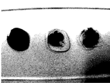
血液15マイクロリットル(μL)に凝集剤15μLを加え、スライドグラス上に滴下した。そのまま室温で2分間静置した後、写真を撮影した。(図3)
写真は左から、PBS添加、凝集剤+促進剤添加、凝集剤のみ添加である。
凝集剤、凝集剤+促進剤を添加した場合は、添加後数秒ですでに凝固作用が顕著に見られ、血球凝集塊と血漿の分離が観察された。凝集剤添加の場合は分離した血漿中に未凝集の血球が観察されたが、凝集剤+促進剤を添加した場合は未凝集の血球はほとんど観察されなかった。
凝集剤はポリ−L−リジン(分子量30000〜70000、SIGMA社製)、促進剤はオレイル基(SIGMA社製)を用いた。
(Preparation method of flocculant + accelerator)
Poly-L-lysine (molecular weight 30000-70000, manufactured by Sigma) and oleic acid N-hydroxysuccinimide (manufactured by Sigma) were mixed in a DMSO (manufactured by Sigma) solvent in a molar ratio of 1: 1, The reaction was allowed to proceed for 1 hour at room temperature. Thereafter, it was adjusted to a concentration of 370 μM with PBS.
15 μL of the flocculant was added to 15 microliters (μL) of blood and dropped on a slide glass. The photo was taken after standing at room temperature for 2 minutes. (Figure 3)
From the left, the photo shows PBS added, flocculant + accelerator added, and only flocculant added.
When an aggregating agent, an aggregating agent + accelerator was added, the clotting effect was already noticeable within a few seconds after the addition, and the separation of hemagglutinating clot and plasma was observed. In the case of adding an aggregating agent, unaggregated blood cells were observed in the separated plasma, but when an aggregating agent + accelerator was added, almost no unaggregated blood cells were observed.
Poly-L-lysine (molecular weight 30000-70000, manufactured by SIGMA) was used as the flocculant, and oleyl group (manufactured by SIGMA) was used as the accelerator.
本発明は、在宅で微量な血液を滴下するだけで、血球と血液を分離するため、血液の生化学検査や免疫検査、がんの診断や感染症の診断等に好適に用いられる。簡易に、高速で、安価に血球が分離できる本構造物は、産業上で利用可能である。
Since the present invention separates blood cells from blood by simply dropping a small amount of blood at home, it is suitably used for blood biochemical tests, immunological tests, cancer diagnosis, infectious disease diagnosis, and the like . This structure that can separate blood cells easily, at high speed and at low cost can be used industrially.
10 基盤
10H 蓋
11 血球沈殿室
12 流路
13 吸い取り部
14 遮断部
15、17 減速堤
16,18 沈降段差
19 採取流路
20 定量秤取室
21 脱気孔
22 投入口
DESCRIPTION OF
Claims (3)
前記流路(12)の入口側に配置され、血液と血液凝固成分との混合液を一時的に貯留可能な血球沈殿室(11)、前記血球沈殿室(11)内の前記流路(12)の入口側方向に上部へ血球が取り除かれた混合成分が溢れるような形で進行する為に設置された遮断部(14)よりなり、前記混合成分は、前記血球沈殿室(11)へ投入口(22)から、前記遮断部(14)の上部を溢流するまで投入され、前記遮断部(14)の上部を溢流した混合成分が、前記流路(12)内へ毛管力によりとりこまれ、出口方向へ進行することで血液凝固成分と混合成分を分離する血球分離構造物。 The substrate (10) has a configuration in which the cross-sectional area on the inlet side is large and the cross-sectional area decreases toward the outlet side, and a protrusion for temporarily stopping or decelerating the flow of fluid on the inner surface of the inlet side A flow path (12) provided with a suction part (13) on the outlet side,
A blood cell sedimentation chamber (11) disposed on the inlet side of the flow channel (12) and capable of temporarily storing a mixture of blood and blood coagulation components, and the flow channel (12 in the blood cell sedimentation chamber (11)) ) In the direction of the inlet side of the blood vessel, and is formed by a blocking portion (14) installed so that the mixed component from which the blood cells have been removed overflows , and the mixed component is input into the blood cell sedimentation chamber (11). The mixed component that has been introduced from the mouth (22) until it overflows the upper part of the blocking part (14) and has overflowed the upper part of the blocking part (14) is taken into the flow path (12) by capillary force. A blood cell separation structure that separates blood coagulation components and mixed components by rarely moving toward the outlet .
Priority Applications (1)
| Application Number | Priority Date | Filing Date | Title |
|---|---|---|---|
| JP2004111554A JP4509632B2 (en) | 2004-04-05 | 2004-04-05 | Blood cell separation structure |
Applications Claiming Priority (1)
| Application Number | Priority Date | Filing Date | Title |
|---|---|---|---|
| JP2004111554A JP4509632B2 (en) | 2004-04-05 | 2004-04-05 | Blood cell separation structure |
Publications (3)
| Publication Number | Publication Date |
|---|---|
| JP2005292092A JP2005292092A (en) | 2005-10-20 |
| JP2005292092A5 JP2005292092A5 (en) | 2007-06-07 |
| JP4509632B2 true JP4509632B2 (en) | 2010-07-21 |
Family
ID=35325165
Family Applications (1)
| Application Number | Title | Priority Date | Filing Date |
|---|---|---|---|
| JP2004111554A Expired - Fee Related JP4509632B2 (en) | 2004-04-05 | 2004-04-05 | Blood cell separation structure |
Country Status (1)
| Country | Link |
|---|---|
| JP (1) | JP4509632B2 (en) |
Families Citing this family (19)
| Publication number | Priority date | Publication date | Assignee | Title |
|---|---|---|---|---|
| JP2007267635A (en) * | 2006-03-30 | 2007-10-18 | Kitakyushu Foundation For The Advancement Of Industry Science & Technology | Cell separation tool and cell separation method using the same |
| JP2008089381A (en) * | 2006-09-29 | 2008-04-17 | Fujifilm Corp | Plasma collection method and plasma collection device |
| JP2008082896A (en) | 2006-09-27 | 2008-04-10 | Fujifilm Corp | Plasma collection method and instrument |
| JP2008082897A (en) * | 2006-09-27 | 2008-04-10 | Fujifilm Corp | Plasma collection method and device, blood simple test method and device |
| JP2011504591A (en) * | 2007-11-26 | 2011-02-10 | アトノミックス アクティーゼルスカブ | Integrated separation and detection cartridge with means and methods for increasing the signal to noise ratio |
| JP5369111B2 (en) * | 2007-11-26 | 2013-12-18 | アトノミックス アクティーゼルスカブ | Isolation device including physical barrier |
| JP2009195436A (en) * | 2008-02-21 | 2009-09-03 | Jms Co Ltd | Test implement |
| JP5177533B2 (en) * | 2008-09-25 | 2013-04-03 | ローム株式会社 | Microchip |
| CA2753886C (en) | 2009-03-02 | 2018-06-12 | Catholic Healthcare West | Diagnostic devices and methods of use |
| JP5506440B2 (en) | 2010-02-08 | 2014-05-28 | 株式会社堀場製作所 | Liquid sample quantifier |
| SG194064A1 (en) * | 2011-04-08 | 2013-11-29 | Panasonic Corp | Diagnosis kit and method of using the same |
| JP6057251B2 (en) | 2011-11-11 | 2017-01-11 | 国立研究開発法人産業技術総合研究所 | Particle sorting apparatus and particle sorting method |
| WO2016154302A1 (en) * | 2015-03-23 | 2016-09-29 | The University Of North Carolina At Chapel Hill | Universal molecular processor for precision medicine |
| EP3582892A4 (en) | 2017-04-21 | 2020-03-04 | Hewlett-Packard Development Company, L.P. | COPLANAR MICROFLUIDIC HANDLING |
| EP3582894A4 (en) | 2017-04-21 | 2020-03-04 | Hewlett-Packard Development Company, L.P. | MICROFLUIDIC CHIP |
| EP3583416B1 (en) * | 2017-04-21 | 2024-05-29 | Hewlett-Packard Development Company, L.P. | Chip to chip fluidic interconnect |
| US11364496B2 (en) | 2017-04-21 | 2022-06-21 | Hewlett-Packard Development Company, L.P. | Coplanar fluidic interconnect |
| JP7223311B2 (en) * | 2018-08-21 | 2023-02-16 | ウシオ電機株式会社 | CELL CULTURE CHIP AND CELL CULTURE METHOD USING THE SAME |
| KR102698453B1 (en) * | 2021-10-29 | 2024-08-26 | 고려대학교 산학협력단 | Fine particle separation and cleaning apparatus |
Family Cites Families (10)
| Publication number | Priority date | Publication date | Assignee | Title |
|---|---|---|---|---|
| JPS57131451A (en) * | 1981-02-05 | 1982-08-14 | Asahi Chemical Ind | Method and apparatus for separating blood components |
| ATE269160T1 (en) * | 1994-11-14 | 2004-07-15 | Univ Pennsylvania | MINIATURIZED SAMPLE PREPARATION DEVICES AND SYSTEMS FOR DETECTING AND TREATING ANALYTES |
| JP2000135407A (en) * | 1998-10-29 | 2000-05-16 | Miura Co Ltd | Powdery flocculant |
| DE19857215B4 (en) * | 1998-12-11 | 2008-04-10 | Dade Behring Marburg Gmbh | Multiküvettenrotor |
| JP2001281233A (en) * | 2000-03-28 | 2001-10-10 | Inst Of Physical & Chemical Res | Aqueous dispensing microchip and aqueous dispensing method using the same |
| JP3778041B2 (en) * | 2000-12-08 | 2006-05-24 | コニカミノルタホールディングス株式会社 | Particle separation mechanism and particle separation apparatus |
| JP2003083958A (en) * | 2001-09-11 | 2003-03-19 | Jun Kikuchi | Blood analyzer and blood analyzing method |
| DE10313201A1 (en) * | 2003-03-21 | 2004-10-07 | Steag Microparts Gmbh | Microstructured separator and microfluidic process for separating liquid components from a liquid containing particles |
| JP4357902B2 (en) * | 2003-08-29 | 2009-11-04 | セイコーインスツル株式会社 | Liquid separation device and liquid separation method |
| JP2005164330A (en) * | 2003-12-01 | 2005-06-23 | Arkray Inc | Hemocyte separating implement |
-
2004
- 2004-04-05 JP JP2004111554A patent/JP4509632B2/en not_active Expired - Fee Related
Also Published As
| Publication number | Publication date |
|---|---|
| JP2005292092A (en) | 2005-10-20 |
Similar Documents
| Publication | Publication Date | Title |
|---|---|---|
| JP4509632B2 (en) | Blood cell separation structure | |
| US9365815B2 (en) | Particle separation device and method of separating particles | |
| EP2191895B1 (en) | Microparticle analysis device, microfluidic chip for microparticle analysis, and microparticle analysis method | |
| Zhang et al. | High-throughput separation of white blood cells from whole blood using inertial microfluidics | |
| US20050106756A1 (en) | Microstructured separation device, and method for separating liquid components from a liquid containing particles | |
| Inglis et al. | Scaling deterministic lateral displacement arrays for high throughput and dilution-free enrichment of leukocytes | |
| CN111909823A (en) | Inertial micro-fluidic chip for enriching circulating tumor cells | |
| CN108753572B (en) | Lateral offset micro-column array chip and application thereof | |
| JP2017523435A (en) | Device for separating bubbles from a fluid | |
| JP2019512378A (en) | Particle separation device and particle separation method | |
| Ozawa et al. | A numbering-up strategy of hydrodynamic microfluidic filters for continuous-flow high-throughput cell sorting | |
| KR20170080165A (en) | Apparatus of Sorting and Aligning Micro-particles, and Method thereof | |
| KR20160069427A (en) | Apparatus for classifying micro-particles | |
| CN119608256B (en) | Detection method of microfluidic chip and plasma separation and diversion integrated microfluidic chip | |
| Liu et al. | Hydrodynamic separation by changing equilibrium positions in contraction–expansion array channels | |
| US11559808B2 (en) | Microfluidic device | |
| Hoffman et al. | A helical flow, circular microreactor for separating and enriching “smart” polymer–antibody capture reagents | |
| Bilatto et al. | Printed microfluidic filter for heparinized blood | |
| KR101339118B1 (en) | Apparatus for examining fluids | |
| JP2015028497A (en) | Microchip and fine particle analyzer | |
| Chandna et al. | Pillar based microfluidic approach to sorting of microparticle mixtures at various particle ratios | |
| JP2015148625A (en) | Tube for separating part of sample | |
| Kuroda et al. | Microfluidic sedimentation system for separation of plasma from whole blood | |
| CN210787393U (en) | Single-layer micro-fluidic chip with three-dimensional focusing function | |
| US20180161774A1 (en) | High efficiency microfluidic device for trapping circulating tumor cells |
Legal Events
| Date | Code | Title | Description |
|---|---|---|---|
| A521 | Request for written amendment filed |
Free format text: JAPANESE INTERMEDIATE CODE: A523 Effective date: 20070329 |
|
| A621 | Written request for application examination |
Free format text: JAPANESE INTERMEDIATE CODE: A621 Effective date: 20070329 |
|
| A977 | Report on retrieval |
Free format text: JAPANESE INTERMEDIATE CODE: A971007 Effective date: 20090616 |
|
| A131 | Notification of reasons for refusal |
Free format text: JAPANESE INTERMEDIATE CODE: A131 Effective date: 20090623 |
|
| A521 | Request for written amendment filed |
Free format text: JAPANESE INTERMEDIATE CODE: A523 Effective date: 20090821 |
|
| A131 | Notification of reasons for refusal |
Free format text: JAPANESE INTERMEDIATE CODE: A131 Effective date: 20100212 |
|
| A521 | Request for written amendment filed |
Free format text: JAPANESE INTERMEDIATE CODE: A523 Effective date: 20100311 |
|
| TRDD | Decision of grant or rejection written | ||
| A01 | Written decision to grant a patent or to grant a registration (utility model) |
Free format text: JAPANESE INTERMEDIATE CODE: A01 Effective date: 20100405 |
|
| A01 | Written decision to grant a patent or to grant a registration (utility model) |
Free format text: JAPANESE INTERMEDIATE CODE: A01 |
|
| A61 | First payment of annual fees (during grant procedure) |
Free format text: JAPANESE INTERMEDIATE CODE: A61 Effective date: 20100428 |
|
| FPAY | Renewal fee payment (event date is renewal date of database) |
Free format text: PAYMENT UNTIL: 20130514 Year of fee payment: 3 |
|
| R150 | Certificate of patent or registration of utility model |
Free format text: JAPANESE INTERMEDIATE CODE: R150 |
|
| LAPS | Cancellation because of no payment of annual fees |