JP4510941B2 - Cold electrode for gas discharge - Google Patents
Cold electrode for gas discharge Download PDFInfo
- Publication number
- JP4510941B2 JP4510941B2 JP53805298A JP53805298A JP4510941B2 JP 4510941 B2 JP4510941 B2 JP 4510941B2 JP 53805298 A JP53805298 A JP 53805298A JP 53805298 A JP53805298 A JP 53805298A JP 4510941 B2 JP4510941 B2 JP 4510941B2
- Authority
- JP
- Japan
- Prior art keywords
- electrode
- work function
- discharge
- coating
- photoelectric work
- Prior art date
- Legal status (The legal status is an assumption and is not a legal conclusion. Google has not performed a legal analysis and makes no representation as to the accuracy of the status listed.)
- Expired - Fee Related
Links
Images

Classifications
-
- H—ELECTRICITY
- H01—ELECTRIC ELEMENTS
- H01J—ELECTRIC DISCHARGE TUBES OR DISCHARGE LAMPS
- H01J9/00—Apparatus or processes specially adapted for the manufacture, installation, removal, maintenance of electric discharge tubes, discharge lamps, or parts thereof; Recovery of material from discharge tubes or lamps
- H01J9/02—Manufacture of electrodes or electrode systems
- H01J9/022—Manufacture of electrodes or electrode systems of cold cathodes
-
- H—ELECTRICITY
- H01—ELECTRIC ELEMENTS
- H01J—ELECTRIC DISCHARGE TUBES OR DISCHARGE LAMPS
- H01J1/00—Details of electrodes, of magnetic control means, of screens, or of the mounting or spacing thereof, common to two or more basic types of discharge tubes or lamps
- H01J1/02—Main electrodes
- H01J1/025—Hollow cathodes
-
- H—ELECTRICITY
- H01—ELECTRIC ELEMENTS
- H01J—ELECTRIC DISCHARGE TUBES OR DISCHARGE LAMPS
- H01J61/00—Gas-discharge or vapour-discharge lamps
- H01J61/02—Details
- H01J61/04—Electrodes; Screens; Shields
- H01J61/06—Main electrodes
- H01J61/067—Main electrodes for low-pressure discharge lamps
- H01J61/0672—Main electrodes for low-pressure discharge lamps characterised by the construction of the electrode
-
- H—ELECTRICITY
- H01—ELECTRIC ELEMENTS
- H01J—ELECTRIC DISCHARGE TUBES OR DISCHARGE LAMPS
- H01J61/00—Gas-discharge or vapour-discharge lamps
- H01J61/02—Details
- H01J61/04—Electrodes; Screens; Shields
- H01J61/06—Main electrodes
- H01J61/067—Main electrodes for low-pressure discharge lamps
- H01J61/0675—Main electrodes for low-pressure discharge lamps characterised by the material of the electrode
- H01J61/0677—Main electrodes for low-pressure discharge lamps characterised by the material of the electrode characterised by the electron emissive material
-
- H—ELECTRICITY
- H01—ELECTRIC ELEMENTS
- H01J—ELECTRIC DISCHARGE TUBES OR DISCHARGE LAMPS
- H01J61/00—Gas-discharge or vapour-discharge lamps
- H01J61/02—Details
- H01J61/04—Electrodes; Screens; Shields
- H01J61/06—Main electrodes
- H01J61/09—Hollow cathodes
Landscapes
- Engineering & Computer Science (AREA)
- Manufacturing & Machinery (AREA)
- Discharge Lamp (AREA)
- Glass Compositions (AREA)
- Gas-Filled Discharge Tubes (AREA)
- Vessels And Coating Films For Discharge Lamps (AREA)
Abstract
Description
本発明は導電性物質を有するガス放電用電極に関する。
中空カソード効果を利用するガス放電用冷電極は従来から知られており、技術的に、例えば電子管または照明目的のために使用されている(米国特許第1125476号明細書、中空カソード効果に関しては、文献、例えばManfred von Ardenne(Hrsg)“Effekte der Physik und ihre Anwendungen”Verlag Harri Deutsch Thun Frankfurt/Main 1990参照)。
冷電極は、多くの場合に仕事関数を減少するために、内側に、以下に活性物質と記載するアルカリ土類金属酸化物の混合物からなる被覆層を有する(Prinzip von Wehnelt i.J.1907)。酸化物は標準的な周囲条件下で安定でないので、電極の支持体物質に炭酸塩の形の放電被膜を被覆し、低圧および高温で、例えば支持体物質を焼成して相当する酸化物に変換する。
前記の電極の電気的損失は、これと結びついた欠点とともに状態調節の際に、炭酸塩の反応の間は境界条件におよび運転中は放電空間中の残留ガスに顕著に依存し、これが放電能力を低下する(活性物質の毒化)。
従って、本発明の課題は、作業中に境界条件に対して反応せず、ガス放電装置の全部の使用時間中に少ない電気的損失およびそれとともに少ない加熱を有する電極を提供することである。
前記課題は、放電被覆(3)の物質の光電仕事関数が570°Kより低く、有利には420°Kより低い電極の作業温度の範囲内で支持体物質(1)の光電仕事関数より少ないことにより解決される。
従って、本発明の解決手段の核心は、電子を放出する電極の被覆(放電被膜)を光電仕事関数に関して特別の方法で選択することである。
この仕事関数は、典型的には260〜450°Kである電極の作業温度範囲内で電極の支持体物質の仕事関数より少ないことが必要である。支持体物質に関係なく光電仕事関数は0〜500°Kの温度範囲内で5.6×10⁻¹⁹ジュール/電子より少ないことが必要である。具体的に使用可能な被覆物質は請求の範囲3により、イットリウム、プラセオジムまたはルビジウムまたはこれらの混合物である。
光電仕事関数は、電子が電極から放出するために、電子1個当たりの消費されなければならない光電量子エネルギーとして定義される(eV/電子またはジュール/電子で測定される)。
本発明により、低い光電仕事関数を有する表面および高い光電仕事関数を有する表面を組み合わせる。この場合に電子を放出する層は、低温で高い光電仕事関数を有する酸化物の代わりに、支持体物質に比べて低い光電仕事関数を有する金属または半導電性物質からなっていてもよく、しばしば同時に原則的に公知の中空カソード効果を利用する。
本発明の利点は、電極表面の好ましくない化学反応を回避することである。これにより製造中および状態調節中に電極はガス雰囲気にほとんど無関係である。活性物質が毒化されず、反応の際の不完全に行われる反応により後の時点でガス放電空間の雰囲気に反応生成物を放出することもない。
低い光電仕事関数を有する相当する化学的に不活性の物質(例えばイットリウム)を使用することにより、本発明の電極は製造および状態調節の際に、例えば訓練されていない人間による誤った処理から十分に安全である。炭酸塩混合物のための従来必要な製造技術的にきわめて費用のかかる製造方法の回避はかなりの費用の利点を生じることがある。
更に本発明による電極を作動する際に、測定により、酸化物混合物で活性化された同じ大きさおよび構造の電極に比較してかなり少ない加熱が生じる。
種々の温度での光電仕事関数の測定により、作業温度T=300°Kにおいて本発明の電極のかなり低い光電仕事関数が示される(第3図参照)。
酸化物混合物は熱的に活性化されて、低い光電仕事関数を有する。電子の帯域構造が間接的な移行部分を有する不均一な、多成分の、絶縁性の固体から熱により電子を放出する場合は、格子振動(フォノン)が帯域の間隙を最小にして移行部分の活性化に関与する(例えばJoseph Eichmeier Moderne Vakuumelektronik Springer Verlag Berlin 1981参照)。
冷電極を用いるガス放電に関して、光電仕事関数が損失のための決定的な値として見出される。これは特定の状況下で熱により決定される仕事関数と異なる。冷電極中のフォノンエネルギーは熱放出電極中よりかなり低いので、冷電極においては間接的な帯域移行部分が全く活性化されない。
本発明による被覆物質は、ほぼ直接的な帯域移行部分および小さな帯域の間隙を有し、これが活性化工程での高いエネルギーのフォノンの関与を不要にする。
本発明の1つの構成は、電極が中空体として、特にコップ状に形成され、放電被膜(3)が中空体の内側に存在することである。このようにして本発明の被膜の利点に付加的に、中空カソード効果を有利に利用することができる。中空体は特にコップの形を有し、放電被膜が中空体の内側に存在し、ここで電子の放出が行われる。
中空体電極の他の構成においては、放電被膜(3)がその他の電極の表面、特に中空体の外側表面より少ない光電仕事関数を有する。これにより放電被膜の電子放出が濃縮される。
本発明の他の構成により、支持体物質(1)が中空体の外側に、有利にはニッケルまたは白金からなる被覆層(4)を有し、これは高い光電仕事関数、有利には8.0×10⁻¹⁹ジュール/電子より高い光電仕事関数を有する。これは、支持体の外側への放出の広がりを阻止し、それとともに支持体の分解を阻止することにより、有利に作動中の電極の寿命を高めることを可能にする。
支持体物質(1)が、低い光電仕事関数、有利には6.4×10⁻¹⁹ジュール/電子より少ない光電仕事関数を有する本発明の他の構成は、支持体物質および被覆物質が同じであってもよいので、電極空間の内側の特別の被覆を節約できるという利点を有する。
支持体物質は、有利には金属、特に鉄を含有してもよい。内容に関しては支持体物質が金属からなることが特に有利である。
放電被膜(3)は純粋物質に対して光電仕事関数を減少するために、更にドーパント、有利にはドーパント、例えばカルシウム、セシウムまたはバリウムを10−5at%〜1at%の濃度で含有してもよい。これにより、純粋物質の使用に対して電子の帯域構造中の帯域の間隙の減少により、仕事関数の更なる減少およびそれとともに損失の更なる減少を達成できる。
支持体物質(1)の表面の一部に、電子流またはイオン流を抑制するために、電気的に絶縁性の被覆層(4)が備えられていることが更に有利である。これは支持体物質の外側の電子流の完全な抑制という利点を有し、これにより電極の寿命が高まる。
電極のガス放電に向けられる部分は電気的に絶縁性の、温度および真空に安定の物質、有利にはセラミックが被覆されていてもよい。これは、ガス放電に向けられる縁部から出発する、電極の活性物質または支持体物質の飛散が阻止されるという有利な効果を有する。
本発明により、つばを有する電気的に絶縁性のスリーブ(9)が、電極により形成される中空空間の開口内に、つばがガス放電方向の開口の縁部を覆うように配置されていてもよい。これにより、特に前記の飛散の阻止と同時に、絶縁物質からなるシリンダ状の空間中の電極を使用する場合に、例えばリング状の溝の形成が達成される。支持体の外側および電流供給線材への有害な、従って好ましくない放出の広がりが回避される。
電極により形成される中空空間の開口のガス放電に面した縁部は、更に、有利には曲げることによりまたは縁をつけることにより、開口での電場の勾配が減少するように形成されていてもよい。これにより、他の製造技術的部材を必要とせずに飛散速度の部分的な減少が達成される。
更に電極は、有利にはシリンダ状に形成されていてもよい、ガラス成形体(8)に包囲されていてもよい。本発明の他の有利な構成においては、電極はガラス成形体(8)内に、熱伝導性の劣る絶縁物質、有利にはセラミックまたは雲母からなるリング(10)を用いて中心に配置されていてもよい。これにより、例えば電極を状態調節する際に生じるような、機械的負荷(例えば衝突、衝撃)または片側の熱負荷の場合にガラスの破断を回避するための、シリンダ状のガラス成形体内の電極の中心配置が達成される。
更に、金属のコップ、中空シリンダまたは中空円錐の内側に少なくとも部分的に場のない空間が形成されることが有利である。これにより本発明の装置は、存在する製造工具を、自体公知の構造の支持体の製造に使用するために適している。
本発明の装置は、更に、支持体物質(1)の表面の少なくとも一部に反応性ガスを結合する物質(ゲッター)が被覆され、これが例えば電極の状態調節の際に活性化するように形成されていてもよい。これは、ガス放電の希ガス雰囲気が作動中に、場合により放電ガス容器または電極成形体から放出される反応性ガスまたは蒸気の化学的および/または物理的結合により純粋に維持されるという利点を有する。
支持体物質(1)を被覆する物質は水素化物の形で、有利には水素化イットリウムとして被覆されていてもよい。水素化物は電極の状態調節の際に水素を遊離して金属の形に変換する。これは、水銀含有放電ランプ、例えば高圧照明管の再生の際に見出されるように、十分な加熱工程および焼成工程で放電空間に存在する反応性物質の酸化を回避するので有利である。
以下に本発明を実施例により詳細に説明する。
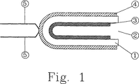
第1図は本発明の例示的構成を示す。その際電極は縦断面図で示される。層厚は説明のために図面では実物大で示されていない。
本発明の電極は、例えば鉄から製造される支持体(1)からなり、例としてコップの形に形成され、ガス放電に面した開口(2)を有する。
支持体(1)の内側は低い光電仕事関数を有する物質、例えばイットリウムの層(3)を有し、この物質は機械的、化学的および/または物理的被覆法(例えば加圧、圧延、蒸発、スパッタリング、電気メッキ、噴霧)により被覆され、一方外側表面(4)は、例えば高い光電仕事関数を有する物質、例えばニッケルまたは白金で被覆されている。
ここでは半球状の端部の形の、支持体(1)の閉鎖された端部に、電流供給線材(5)が自体公知方法で、例えば点溶接により固定されている。
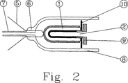
第2図は例として、例えば高圧照明管に使用するための、ガス放電容器の部材として、自体公知の構造でシリンダ状ガラス成形体(8)に埋め込まれた、本発明の電極の縦断面図を示す。その際電流供給線材(5)は圧搾底部(6)で真空密にガラス成形体(8)とともに封止されている。圧搾底部(6)に付加的に融合されるガラス管(7)は第2図に示されていないガス放電容器を真空にするために用いられる。電極は一般にガラス成形体(8)を用いてガス放電容器に取り付けられている。
更に第2図は、例えばセラミックからなる絶縁性保護リング(9)を有する支持体(1)の開口(2)を示し、該リングは自体公知方法で支持体(1)に圧搾、巻き込み、縁取り、圧延等により固定される。
同様に保護リング(9)と支持体(1)の間に、例えば雲母からなる付加的な中心リング(10)が例として示される。これはシリンダ状ガラス成形体(8)内に電極が中心に配置されることを保証する。中心リング(10)は、付属管(7)によりガス放電容器の流動技術的に有利な真空を可能にするために、円環の形から離れて、例えば刻み目等を有していてもよい。
第3図は本発明の構成と比較した種々の市販の電極の光電仕事関数の測定の比較した結果を示す。
図面の電極の説明は以下のとおりである。

Cold electrodes for gas discharge utilizing the hollow cathode effect are known in the art and are used in the art, for example for electron tubes or lighting purposes (US Pat. No. 1,125,476, for the hollow cathode effect, Literature, see, for example, Manfred von Ardenne (Hrsg) “Effekte der Physik und ihr Anwenwengen” Verlag Harris Deutsch Schoon Frankfurt / Main 1990).
In order to reduce the work function in many cases, the cold electrode has a coating layer on the inside which consists of a mixture of alkaline earth metal oxides, described below as active substances (Prinzip von Wehnelt i.J. 1907). . Since oxides are not stable under standard ambient conditions, the electrode support material is coated with a discharge coating in the form of a carbonate and converted to the corresponding oxide by firing, for example, the support material at low and high temperatures. To do.
The electrical losses of the electrodes, along with the disadvantages associated with them, depend significantly on the boundary conditions during the carbonate reaction during the conditioning and on the residual gas in the discharge space during operation, which is the discharge capacity. Decrease (poisoning of active substance).
Accordingly, it is an object of the present invention to provide an electrode that does not react to boundary conditions during operation and has low electrical loss and with it low heating during the entire use time of the gas discharge device.
The object is that the photoelectric work function of the material of the discharge coating (3) is less than the photoelectric work function of the support material (1) in the range of the electrode working temperature lower than 570 ° K, preferably lower than 420 ° K. Is solved.
Therefore, the core of the solution of the present invention is to select the electrode coating ( discharge coating) that emits electrons in a special way with respect to the photoelectric work function.
This work function should be less than the work function of the electrode support material within the working temperature range of the electrode, typically 260-450 ° K. Regardless of the support material, the photoelectric work function should be less than 5.6 × 10 −19 joules / electrons within the temperature range of 0-500 ° K. Specifically usable coating materials are, according to
Photoelectric work function is defined as the photoelectric quantum energy that must be consumed per electron in order for electrons to be emitted from the electrode (measured in eV / electron or joule / electron).
According to the invention, a surface having a low photoelectric work function and a surface having a high photoelectric work function are combined. In this case, the electron emitting layer may consist of a metal or semiconducting material having a low photoelectric work function compared to the support material, instead of an oxide having a high photoelectric work function at low temperatures, and often At the same time, the known hollow cathode effect is used in principle.
An advantage of the present invention is to avoid undesirable chemical reactions on the electrode surface. This makes the electrode almost independent of the gas atmosphere during manufacturing and conditioning. The active substance is not poisoned and does not release reaction products into the atmosphere of the gas discharge space at a later time due to incomplete reactions during the reaction.
By using a corresponding chemically inert material (eg yttrium) having a low photoelectric work function, the electrode of the present invention is sufficient during manufacture and conditioning, eg, from erroneous handling by untrained humans. Safe. Avoidance of the conventionally required manufacturing technology for carbonate mixtures, which is very expensive, can result in considerable cost advantages.
Furthermore, when operating the electrodes according to the invention, the measurement results in considerably less heating compared to electrodes of the same size and structure activated with the oxide mixture.
Measurement of the photoelectric work function at various temperatures shows a much lower photoelectric work function of the electrode of the invention at working temperature T = 300 ° K (see FIG. 3).
The oxide mixture is thermally activated and has a low photoelectric work function. When the electron band structure emits heat electrons from a heterogeneous, multi-component, insulating solid with an indirect transition, the lattice vibration (phonon) minimizes the band gap and It is involved in activation (see, for example, Joseph Eichmeier Moderne Vakuumelektronik Springer Verlag Berlin 1981).
For gas discharges using cold electrodes, the photoelectric work function is found as a critical value for loss. This is different from the work function determined by heat under certain circumstances. Since the phonon energy in the cold electrode is much lower than in the heat emitting electrode, no indirect band transition is activated in the cold electrode.
The coating material according to the invention has a nearly direct zone transition and a small zone gap, which obviates the involvement of high energy phonons in the activation process.
One configuration of the present invention is that the electrode is formed as a hollow body, particularly in a cup shape, and the discharge coating (3) exists inside the hollow body. In this way, in addition to the advantages of the coating of the invention, the hollow cathode effect can be used to advantage. The hollow body has a cup shape in particular, and a discharge coating is present inside the hollow body, where electrons are emitted.
In other configurations of the hollow body electrode, the discharge coating (3) has a smaller photoelectric work function than the surface of the other electrode, in particular the outer surface of the hollow body. This concentrates the electron emission of the discharge coating.
According to another configuration of the invention, the support material (1) has a coating layer (4), preferably made of nickel or platinum, on the outside of the hollow body, which has a high photoelectric work function, preferably 8. It has a photoelectric work function higher than 0 × 10 −19 joules / electron. This makes it possible to advantageously increase the lifetime of the active electrode by preventing the spreading of the release to the outside of the support and, together with preventing the decomposition of the support.
Other configurations of the invention in which the support material (1) has a low photoelectric work function, preferably less than 6.4 × 10 −19 joules / electron, are the same for the support material and the coating material. There may be the advantage that a special coating inside the electrode space can be saved.
The support material may advantageously contain a metal, in particular iron. In terms of content, it is particularly advantageous that the support material consists of metal.
The discharge coating (3) may further contain a dopant, preferably a dopant such as calcium, cesium or barium, in a concentration of 10 −5 at% to 1 at%, in order to reduce the photoelectric work function relative to the pure substance. Good. Thereby, a further reduction in work function and a further reduction in loss can be achieved by reducing the band gap in the band structure of electrons for the use of pure materials.
It is further advantageous that a part of the surface of the support material (1) is provided with an electrically insulating coating layer (4) in order to suppress electron or ion flow. This has the advantage of complete suppression of the electron flow outside the support material, which increases the life of the electrode.
The part of the electrode directed to the gas discharge may be coated with an electrically insulating, temperature and vacuum stable material, preferably ceramic. This has the advantageous effect that the scattering of the active or support material of the electrode starting from the edge directed to the gas discharge is prevented.
According to the invention, an electrically insulating sleeve (9) with a collar is arranged in the opening of the hollow space formed by the electrodes so that the collar covers the edge of the opening in the gas discharge direction. Good. As a result, the formation of, for example, a ring-shaped groove is achieved particularly when the electrode in the cylindrical space made of an insulating material is used simultaneously with the prevention of the scattering. Harmful and therefore undesired spread of emissions to the outside of the support and to the current supply wire is avoided.
The edge facing the gas discharge of the opening of the hollow space formed by the electrode may be further formed to reduce the gradient of the electric field at the opening, preferably by bending or fringing. Good. This achieves a partial reduction in the scattering speed without the need for other manufacturing technology components.
Furthermore, the electrode may be surrounded by a glass body (8), which may advantageously be formed in a cylinder. In another advantageous configuration of the invention, the electrode is centrally arranged in the glass body (8) using an insulating material with poor thermal conductivity, preferably a ring (10) made of ceramic or mica. May be. This allows the electrode in the cylindrical glass body to avoid glass breakage in the case of mechanical loads (eg collisions, impacts) or thermal loads on one side, such as occurs when conditioning the electrodes. Center placement is achieved.
Furthermore, it is advantageous that a space that is at least partly free of field is formed inside a metal cup, hollow cylinder or hollow cone. The apparatus according to the invention is thereby suitable for using existing production tools for the production of supports of known construction.
The device of the present invention is further formed so that at least a part of the surface of the support material (1) is coated with a substance (getter) that binds a reactive gas, which is activated, for example, during conditioning of the electrode. May be. This has the advantage that the noble gas atmosphere of the gas discharge is maintained pure during operation, possibly by chemical and / or physical combination of reactive gases or vapors released from the discharge gas vessel or electrode compact. Have.
The material covering the support material (1) may be in the form of a hydride, preferably coated as yttrium hydride. The hydride liberates hydrogen during the conditioning of the electrode and converts it to the metal form. This is advantageous because it avoids the oxidation of reactive substances present in the discharge space with sufficient heating and firing steps, as found during regeneration of mercury-containing discharge lamps, such as high pressure lighting tubes.
Hereinafter, the present invention will be described in detail with reference to examples.
FIG. 1 shows an exemplary configuration of the present invention. The electrodes are then shown in longitudinal section. The layer thickness is not shown to scale in the drawings for purposes of illustration.
The electrode of the present invention comprises a support (1) made of, for example, iron, is formed in the shape of a cup as an example, and has an opening (2) facing the gas discharge .
The inside of the support (1) has a material with a low photoelectric work function, for example a layer of yttrium (3), which can be mechanically, chemically and / or physically coated (for example pressure, rolling, evaporation) , Sputtering, electroplating, spraying), while the outer surface (4) is, for example, coated with a material having a high photoelectric work function, such as nickel or platinum.
Here, the current supply wire (5) is fixed to the closed end of the support (1) in the form of a hemispherical end in a manner known per se, for example by spot welding.
FIG. 2 shows, as an example, a longitudinal sectional view of an electrode of the present invention embedded in a cylindrical glass molded body (8) with a known structure as a member of a gas discharge vessel for use in, for example, a high-pressure lighting tube. Indicates. At this time, the current supply wire (5) is sealed together with the glass molded body (8) in a vacuum-tight manner at the compressed bottom (6). A glass tube (7), which is additionally fused to the squeeze bottom (6), is used to evacuate the gas discharge vessel not shown in FIG. The electrode is generally attached to the gas discharge vessel using a glass molded body (8).
Furthermore, FIG. 2 shows the opening (2) of the support (1) having an insulating protective ring (9) made of ceramic, for example, which is squeezed, rolled up and trimmed into the support (1) in a manner known per se. Fixed by rolling or the like.
Similarly, an additional central ring (10) made of, for example, mica is shown as an example between the guard ring (9) and the support (1). This ensures that the electrode is centered in the cylindrical glass body (8). The central ring (10) may have, for example, a notch, away from the shape of an annulus, in order to allow a technically advantageous vacuum of the gas discharge vessel by means of the attachment tube (7).
FIG. 3 shows the comparison results of the measurement of the photoelectric work function of various commercially available electrodes compared to the configuration of the present invention.
The description of the electrodes in the drawing is as follows.
Claims (15)
Applications Claiming Priority (3)
| Application Number | Priority Date | Filing Date | Title |
|---|---|---|---|
| DE29703990U DE29703990U1 (en) | 1997-03-05 | 1997-03-05 | Cold electrode for gas discharges |
| DE29703990.3 | 1997-03-05 | ||
| PCT/DE1998/000595 WO1998039791A2 (en) | 1997-03-05 | 1998-02-28 | Cold electrode for gas discharges |
Publications (2)
| Publication Number | Publication Date |
|---|---|
| JP2000510996A JP2000510996A (en) | 2000-08-22 |
| JP4510941B2 true JP4510941B2 (en) | 2010-07-28 |
Family
ID=8036992
Family Applications (1)
| Application Number | Title | Priority Date | Filing Date |
|---|---|---|---|
| JP53805298A Expired - Fee Related JP4510941B2 (en) | 1997-03-05 | 1998-02-28 | Cold electrode for gas discharge |
Country Status (8)
| Country | Link |
|---|---|
| US (1) | US6417607B1 (en) |
| EP (1) | EP0907960B1 (en) |
| JP (1) | JP4510941B2 (en) |
| CN (1) | CN1152411C (en) |
| AT (1) | ATE387008T1 (en) |
| BR (1) | BR9805925A (en) |
| DE (2) | DE29703990U1 (en) |
| WO (1) | WO1998039791A2 (en) |
Families Citing this family (11)
| Publication number | Priority date | Publication date | Assignee | Title |
|---|---|---|---|---|
| GB9716640D0 (en) * | 1997-08-07 | 1997-10-15 | Smiths Industries Plc | Electrode structures and lamps |
| JP2002289138A (en) * | 2001-03-28 | 2002-10-04 | Matsushita Electric Ind Co Ltd | Cold cathode fluorescent lamp |
| CN1879192B (en) * | 2003-11-13 | 2012-03-21 | 株式会社新王材料 | Cladding material for discharge electrode and discharge electrode |
| JP2005209382A (en) * | 2004-01-20 | 2005-08-04 | Sony Corp | Discharge lamps and discharge lamp electrodes |
| TWI298509B (en) * | 2005-06-27 | 2008-07-01 | Delta Electronics Inc | Cold cathode fluorescent lamp and electrode thereof |
| DE112006002464T5 (en) * | 2005-09-14 | 2008-07-24 | Littelfuse, Inc., Des Plaines | Gas-filled surge arrester, activating connection, ignition strips and manufacturing process therefor |
| KR101344990B1 (en) * | 2006-04-20 | 2013-12-24 | 신에쓰 가가꾸 고교 가부시끼가이샤 | Conductive, plasma-resistant member |
| KR100933492B1 (en) * | 2008-04-17 | 2009-12-23 | 스미토모덴키고교가부시키가이샤 | Electrode member for cold cathode fluorescent lamp and its manufacturing method |
| CN103035455A (en) * | 2010-01-14 | 2013-04-10 | 宜昌劲森照明电子有限公司 | Cold cathode fluorescent lamp electrode inner coating method |
| US20130162136A1 (en) * | 2011-10-18 | 2013-06-27 | David A. Baldwin | Arc devices and moving arc couples |
| CN103065906B (en) * | 2012-12-18 | 2015-04-22 | 中国人民解放军国防科学技术大学 | Preparation method for carbon fiber annular cathode |
Family Cites Families (27)
| Publication number | Priority date | Publication date | Assignee | Title |
|---|---|---|---|---|
| US1125476A (en) * | 1911-11-09 | 1915-01-19 | Georges Claude | System of illuminating by luminescent tubes. |
| NL141698B (en) * | 1964-12-10 | 1974-03-15 | Philips Nv | INDIRECTLY HEATED CATHOD FOR AN ELECTRIC DISCHARGE TUBE. |
| US3641298A (en) * | 1967-07-19 | 1972-02-08 | Mallory & Co Inc P R | Electrically conductive material and electrical contact |
| US3629916A (en) * | 1967-07-27 | 1971-12-28 | Perkin Elmer Corp | Making alkali metal alloys for cathode lamps |
| NL6804720A (en) * | 1968-04-04 | 1969-10-07 | ||
| GB1425203A (en) * | 1973-06-28 | 1976-02-18 | Claudgen Ltd | Cold cathode electric discharge devices |
| JPS53632B2 (en) * | 1973-08-03 | 1978-01-10 | ||
| US4117374A (en) | 1976-12-23 | 1978-09-26 | General Electric Company | Fluorescent lamp with opposing inversere cone electrodes |
| JPS5542226U (en) * | 1978-09-14 | 1980-03-18 | ||
| JPS57107539A (en) * | 1980-12-25 | 1982-07-05 | Toshiba Corp | Hollow-cathode device |
| US4461970A (en) * | 1981-11-25 | 1984-07-24 | General Electric Company | Shielded hollow cathode electrode for fluorescent lamp |
| CH659916A5 (en) | 1983-03-31 | 1987-02-27 | Inst Radiotekh Elektron | CATODE AND GAS DISCHARGE TUBES, DESIGNED ON THE BASIS OF THIS CATODE. |
| CA1227521A (en) | 1983-10-06 | 1987-09-29 | Philip J. White | Emissive material for high intensity sodium vapor discharge device |
| US4620128A (en) | 1985-04-29 | 1986-10-28 | General Electric Company | Tungsten laden emission mix of improved stability |
| US4795942A (en) * | 1987-04-27 | 1989-01-03 | Westinghouse Electric Corp. | Hollow cathode discharge device with front shield |
| JPH027345A (en) * | 1988-06-24 | 1990-01-11 | Mitsubishi Electric Corp | Electrode for cold cathode discharge lamp |
| JPH0246647A (en) * | 1988-08-05 | 1990-02-16 | Okaya Electric Ind Co Ltd | Display discharge lamp |
| JPH04149954A (en) * | 1990-10-15 | 1992-05-22 | Erebamu:Kk | Discharge lamp |
| US5111108A (en) | 1990-12-14 | 1992-05-05 | Gte Products Corporation | Vapor discharge device with electron emissive material |
| JPH04272109A (en) * | 1991-02-27 | 1992-09-28 | Toshiba Corp | Electrode material for cold cathode fluorescent lamp and electrode constituted of the above |
| JP2852140B2 (en) * | 1991-05-14 | 1999-01-27 | ウシオ電機株式会社 | Fluorescent lamp |
| JP2769933B2 (en) * | 1991-06-17 | 1998-06-25 | 株式会社ノリタケカンパニーリミテド | Direct current discharge display tube and composition for forming cathode thereof |
| JPH05275061A (en) * | 1992-03-24 | 1993-10-22 | Hitachi Ltd | Hollow cathode lamp and manufacture thereof |
| JPH083718A (en) * | 1994-06-16 | 1996-01-09 | Toshiba Corp | Method for manufacturing spray-coated metal member |
| JPH08227691A (en) * | 1995-02-21 | 1996-09-03 | Kunimasa Sakurai | Neon tube |
| JP3107743B2 (en) * | 1995-07-31 | 2000-11-13 | カシオ計算機株式会社 | Electron-emitting electrode, method of manufacturing the same, and cold cathode fluorescent tube and plasma display using the same |
| JPH10177712A (en) * | 1996-12-16 | 1998-06-30 | Hoya Corp | Magnetic recording medium |
-
1997
- 1997-03-05 DE DE29703990U patent/DE29703990U1/en not_active Expired - Lifetime
-
1998
- 1998-02-28 AT AT98916816T patent/ATE387008T1/en not_active IP Right Cessation
- 1998-02-28 US US09/180,339 patent/US6417607B1/en not_active Expired - Fee Related
- 1998-02-28 WO PCT/DE1998/000595 patent/WO1998039791A2/en not_active Ceased
- 1998-02-28 EP EP98916816A patent/EP0907960B1/en not_active Expired - Lifetime
- 1998-02-28 CN CNB988002426A patent/CN1152411C/en not_active Expired - Fee Related
- 1998-02-28 BR BR9805925-4A patent/BR9805925A/en not_active Application Discontinuation
- 1998-02-28 JP JP53805298A patent/JP4510941B2/en not_active Expired - Fee Related
- 1998-02-28 DE DE59814169T patent/DE59814169D1/en not_active Expired - Lifetime
Also Published As
| Publication number | Publication date |
|---|---|
| US6417607B1 (en) | 2002-07-09 |
| WO1998039791A2 (en) | 1998-09-11 |
| DE29703990U1 (en) | 1997-04-17 |
| EP0907960A2 (en) | 1999-04-14 |
| BR9805925A (en) | 2000-04-25 |
| EP0907960B1 (en) | 2008-02-20 |
| WO1998039791A3 (en) | 1999-03-04 |
| CN1152411C (en) | 2004-06-02 |
| DE59814169D1 (en) | 2008-04-03 |
| CN1219283A (en) | 1999-06-09 |
| ATE387008T1 (en) | 2008-03-15 |
| JP2000510996A (en) | 2000-08-22 |
Similar Documents
| Publication | Publication Date | Title |
|---|---|---|
| US6044130A (en) | Transmission type X-ray tube | |
| JP4510941B2 (en) | Cold electrode for gas discharge | |
| US3582702A (en) | Thermionic electron-emissive electrode with a gas-binding material | |
| US2147447A (en) | Glow cathode | |
| US4843266A (en) | Metal-halogen discharge lamp with conically shaped insulating elements in outer envelope | |
| US3619699A (en) | Discharge lamp having cavity electrodes | |
| CN108878232B (en) | Hot cathode assembly for vacuum electronic devices | |
| US3400294A (en) | Heated cathode and method of manufacture | |
| US6274981B1 (en) | Low-pressure mercury vapor discharge lamp with electrode shield | |
| RU2160942C2 (en) | Filamentary cathode | |
| EP1150335B1 (en) | Electrode for discharge tube and discharge tube using it | |
| US5675214A (en) | Low-pressure discharge lamp having hollow electrodes | |
| JP2001035438A (en) | Method of manufacturing fluorescent lamp and electrode assembly for fluorescent lamp | |
| EP1150334B1 (en) | Electrode for discharge tube and discharge tube using it | |
| JPH11502056A (en) | Low pressure discharge lamp | |
| JP2004525494A (en) | Low pressure mercury vapor discharge lamp | |
| US2112855A (en) | Electrode for discharge lamps | |
| JPH11339713A (en) | Electrode for discharge tube | |
| EP0122107B1 (en) | Electrical lead-ins for use for arc sustaining atmospheres | |
| US6380676B1 (en) | Discharge lamp with end of life arc extinguishing structure | |
| KR950010691Y1 (en) | Cathod of crt electron gun | |
| JP2001283771A (en) | Rare gas discharge tube | |
| KR810000074Y1 (en) | Moveable electrode manufacturing method for lighting lamp | |
| US20230202930A1 (en) | Electron-emitting ceramic | |
| US3264507A (en) | Electric discharge device structure having separate heater and discharge compartments |
Legal Events
| Date | Code | Title | Description |
|---|---|---|---|
| A621 | Written request for application examination |
Free format text: JAPANESE INTERMEDIATE CODE: A621 Effective date: 20041217 |
|
| A977 | Report on retrieval |
Free format text: JAPANESE INTERMEDIATE CODE: A971007 Effective date: 20070525 |
|
| A131 | Notification of reasons for refusal |
Free format text: JAPANESE INTERMEDIATE CODE: A131 Effective date: 20070619 |
|
| A977 | Report on retrieval |
Free format text: JAPANESE INTERMEDIATE CODE: A971007 Effective date: 20070523 |
|
| A601 | Written request for extension of time |
Free format text: JAPANESE INTERMEDIATE CODE: A601 Effective date: 20070919 |
|
| A602 | Written permission of extension of time |
Free format text: JAPANESE INTERMEDIATE CODE: A602 Effective date: 20071029 |
|
| A601 | Written request for extension of time |
Free format text: JAPANESE INTERMEDIATE CODE: A601 Effective date: 20071019 |
|
| A602 | Written permission of extension of time |
Free format text: JAPANESE INTERMEDIATE CODE: A602 Effective date: 20071126 |
|
| A521 | Request for written amendment filed |
Free format text: JAPANESE INTERMEDIATE CODE: A523 Effective date: 20071119 |
|
| A131 | Notification of reasons for refusal |
Free format text: JAPANESE INTERMEDIATE CODE: A131 Effective date: 20080624 |
|
| A601 | Written request for extension of time |
Free format text: JAPANESE INTERMEDIATE CODE: A601 Effective date: 20080924 |
|
| A602 | Written permission of extension of time |
Free format text: JAPANESE INTERMEDIATE CODE: A602 Effective date: 20081031 |
|
| A521 | Request for written amendment filed |
Free format text: JAPANESE INTERMEDIATE CODE: A523 Effective date: 20081024 |
|
| A131 | Notification of reasons for refusal |
Free format text: JAPANESE INTERMEDIATE CODE: A131 Effective date: 20090217 |
|
| A521 | Request for written amendment filed |
Free format text: JAPANESE INTERMEDIATE CODE: A523 Effective date: 20090515 |
|
| TRDD | Decision of grant or rejection written | ||
| A01 | Written decision to grant a patent or to grant a registration (utility model) |
Free format text: JAPANESE INTERMEDIATE CODE: A01 Effective date: 20100406 |
|
| A01 | Written decision to grant a patent or to grant a registration (utility model) |
Free format text: JAPANESE INTERMEDIATE CODE: A01 |
|
| A61 | First payment of annual fees (during grant procedure) |
Free format text: JAPANESE INTERMEDIATE CODE: A61 Effective date: 20100506 |
|
| FPAY | Renewal fee payment (event date is renewal date of database) |
Free format text: PAYMENT UNTIL: 20130514 Year of fee payment: 3 |
|
| R150 | Certificate of patent or registration of utility model |
Free format text: JAPANESE INTERMEDIATE CODE: R150 |
|
| LAPS | Cancellation because of no payment of annual fees |