JP4517536B2 - Solar heat collector - Google Patents
Solar heat collector Download PDFInfo
- Publication number
- JP4517536B2 JP4517536B2 JP2001149071A JP2001149071A JP4517536B2 JP 4517536 B2 JP4517536 B2 JP 4517536B2 JP 2001149071 A JP2001149071 A JP 2001149071A JP 2001149071 A JP2001149071 A JP 2001149071A JP 4517536 B2 JP4517536 B2 JP 4517536B2
- Authority
- JP
- Japan
- Prior art keywords
- heat
- air
- panel
- heat collecting
- collecting
- Prior art date
- Legal status (The legal status is an assumption and is not a legal conclusion. Google has not performed a legal analysis and makes no representation as to the accuracy of the status listed.)
- Expired - Fee Related
Links
Images

Classifications
-
- Y—GENERAL TAGGING OF NEW TECHNOLOGICAL DEVELOPMENTS; GENERAL TAGGING OF CROSS-SECTIONAL TECHNOLOGIES SPANNING OVER SEVERAL SECTIONS OF THE IPC; TECHNICAL SUBJECTS COVERED BY FORMER USPC CROSS-REFERENCE ART COLLECTIONS [XRACs] AND DIGESTS
- Y02—TECHNOLOGIES OR APPLICATIONS FOR MITIGATION OR ADAPTATION AGAINST CLIMATE CHANGE
- Y02E—REDUCTION OF GREENHOUSE GAS [GHG] EMISSIONS, RELATED TO ENERGY GENERATION, TRANSMISSION OR DISTRIBUTION
- Y02E10/00—Energy generation through renewable energy sources
- Y02E10/40—Solar thermal energy, e.g. solar towers
- Y02E10/44—Heat exchange systems
Landscapes
- Heat-Pump Type And Storage Water Heaters (AREA)
Description
【0001】
【発明の属する技術分野】
本発明は太陽熱を集熱して給湯、暖房に利用する太陽熱集熱装置に関するものである。
【0002】
【従来の技術】
従来、この種の太陽熱利用のヒートポンプ装置としては、例えば、特開昭59−15778号公報に記載されているようなものがあった。図8は前記公報に記載された従来の太陽熱利用装置を示すものである。
【0003】
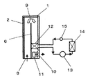
図8において、1は外箱、2は透明板、6は外箱1内を表側と裏側に仕切るように配置した集熱板、8は外気取入口、9は集熱板6の表側を流れてきた空気を集熱板6の裏側へリターンするリターン口、10は集熱板6の裏側を流れてきた空気を排気する排気口であり、外気取入口8近傍の外箱1の裏側に配置されている。12は蒸発器であり、圧縮機13、凝縮器14、減圧弁15と連結してヒートポンプ装置を形成する。
【0004】
【発明が解決しようとする課題】
しかしながら、前記従来の構成では、外気から取入れた低温空気を集熱板9の表側に流して徐々に昇温し、昇温した空気をリターンさせて集熱板9の裏側に流すようになっている。しかし、集熱板9に沿って流れる空気は下流の出口に近づくにつれて高温となるため
、比体積が増大する。そして、集熱板9を表側から裏側へ往復するため空気流路が長くなる。そのため、空気流路抵抗が増加して、必要風量が得られないため蒸発器12での熱交換量が低下する。また、風量不足のために空気温度が異常上昇して外箱から外気へ放熱する量が増加する。よって、熱交換量の低下と放熱量の低下を防止するために送風手段を大型化して必要風量を確保することになる。その結果、消費電力量が大きくなる。
【0005】
本発明は、上記従来の課題を解決するもので、集熱ユニットと集熱パネルで囲まれた空気通路面積を空気吸込み側の集熱パネル入口側よりも下流の出口側で次第に大きくなるようにして通風抵抗を飛躍的に低減し、送風手段の省電力化をはかる太陽熱集熱装置を提供するものである。
【0006】
【課題を解決するための手段】
前記従来の課題を解決するために、本発明の太陽熱集熱装置は、太陽熱を集熱する集熱パネルと、太陽光を少なくとも前記集熱パネルへ透過する透過体と、表面に前記透過体と、前記集熱パネルを収納する集熱ユニットと、前記集熱ユニットの内部へ空気を導入する空気吸込み部と、前記集熱パネルを通過する空気が流れる空気熱交換器と、前記空気吸込み部、前記集熱パネル、前記空気熱交換器の順に空気を搬送する送風手段とを備え、空気吸込み側の集熱パネル入口側より出口側の前記集熱パネルの巾を大きくすることで、前記集熱ユニットと前記集熱パネルで囲まれた空気通路面積が、空気吸込み側の集熱パネル入口側から下流の出口側へ次第に大きくなるように構成したことを特徴とするものである。これによって、集熱パネル出口に近づくにつれて空気通路面積を大きくし、高温空気の空気通過風速を低減して、空気流路抵抗の増加を防止するものである。
【0007】
【発明の実施の形態】
請求項1に記載の発明は、太陽熱を集熱する集熱パネルと、太陽光を少なくとも前記集熱パネルへ透過する透過体と、表面に前記透過体と、前記集熱パネルを収納する集熱ユニットと、前記集熱ユニットの内部へ空気を導入する空気吸込み部と、前記集熱パネルを通過する空気が流れる空気熱交換器と、前記空気吸込み部、前記集熱パネル、前記空気熱交換器の順に空気を搬送する送風手段とを備え、空気吸込み側の集熱パネル入口側より出口側の前記集熱パネルの巾を大きくすることで、前記集熱ユニットと前記集熱パネルで囲まれた空気通路面積が、空気吸込み側の集熱パネル入口側から下流の出口側へ次第に大きくなるように構成して、集熱パネル出口に近づくにつれて空気通路面積を大きくし、高温空気の空気通過風速を低減して、空気流路抵抗の増加を防止して、送風手段の省電力化を実現するものである。
【0008】
【実施例】
以下、本発明の実施例について、図面を参照しながら説明する。なお、従来例および各実施例において、同じ構成、同じ動作をするものについては同一符号を付し、一部説明を省略する。
【0009】
(実施例1)
図1は本発明の第1の実施例における太陽熱集熱装置の構成図を示すものである。また図2はこの太陽熱集熱装置を用いた給湯装置の構成図、図3はこの太陽熱集熱装置を用いた暖房装置の構成図を示すものである。そして、図1、図2、図3において、実線矢印は空気の流れ方向、破線矢印はヒートポンプ装置の冷媒流れ方向、一点鎖線矢印は水流れ方向を表わす。
【0010】
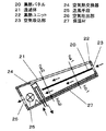
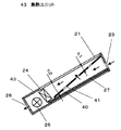
図1において、20は集熱パネルであり、太陽熱を集熱する。21は透過体であり、ガラス材料からなり太陽光を少なくとも集熱パネル20へ透過する。22は集熱ユニットであり、表面に透過体21を備え、集熱パネル20を収納する。23は空気吸込み部であり、集熱ユニット22の内部へ空気を導入する。24は空気熱交換器であり、フィンチューブ型構成として、集熱パネル20を介して集熱した空気が流れ、空気熱交換器24内部を流れる集熱媒体と熱交換する。25は送風手段であり、空気吸込み部23、集熱パネル20、空気熱交換器24の順に空気を搬送する。そして、集熱ユニット22と集熱パネル20で囲まれた空気通路面積を空気吸込み23側の集熱パネル入口側よりも下流の出口側で次第に大きくなるように構成する。
【0011】
そして、図1のように空気が集熱パネル20の表裏の両面を流れて空気熱交換器24へ流入する構成では、集熱ユニット22と集熱パネル20で囲まれた空気の流れる空間距離を集熱パネル20の入口側ha1(表側)、hb1(裏側)、集熱パネル20の出口側ha2(表側)、hb2(裏側)とすると、ha2をha1より大きく、hb2をhb1より大きくするように構成したものであり、集熱ユニット22のユニット巾を入口側と出口側で同じサイズで構成する。26は空気吐出部であり、空気熱交換器24から流出する空気を外気へ排気する箇所である。27は保温材であり、透過体21と反対側の集熱ユニット22外装に設けられている。
【0012】
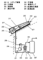
図2おいて、28はヒートポンプ装置であり、空気熱交換器24、圧縮機29、凝縮器30、減圧手段31を順次連結して空気熱交換器24を蒸発器として作用させる。32は貯湯槽、33は循環ポンプ、34は給湯熱交換器であり、凝縮器30と熱交換関係を有する。そして、貯湯槽32、循環ポンプ33、給湯熱交換器34で給湯回路35を構成する。図3において、36は室内器、37はヒートポンプ装置であり、空気熱交換器24、圧縮機29、室内器36、減圧手段31を順次連結して空気熱交換器24を蒸発器として作用させ、室内器36を凝縮器として作用させる。
【0013】
以上のように構成された太陽熱集熱装置について、以下その動作、作用を説明する。図1において、空気吸込み部23から流入した空気を集熱ユニット22と集熱パネル20で囲まれた集熱パネル20の表裏両面の空間へ流す。そして、空間を流れる空気は太陽光熱で高温に加熱されている集熱パネル20から集熱して昇温しながら流れる。そして、昇温しながら集熱パネル20の出口側へ流れ、空気熱交換器24の外部フィン間を流れ、その時、空気熱交換器24の内部を流れる集熱媒体と熱交換して、集熱媒体を加熱する。
【0014】
この動作において、集熱パネル20に沿って流れる空気は下流の出口側へ流れるにつれて温度上昇するため、空気の比体積が大きくなって、通風抵抗が増大して必要風量が確保できない。そのため空気温度が異常に上昇して集熱ユニットから放熱したり、風量不足のため空気熱交換器24と集熱媒体の熱交換量が低下する。しかし、下流側になるにつれて空気通路面積を集熱パネル20表側でha1からha2へ、裏側でhb1からhb2へ大きくしているため、通風抵抗の増加がない。従って、送風手段の大型化を防止して、効率よく集熱して効率よく空気熱交換と熱交換する必要風量を確保することができる。よって、送風手段の省電力化を達成して高効率化を実現する。
【0015】
また、空気が集熱パネル20の表裏の両面を流れて空気熱交換器24へ流入する構成にして、集熱ユニット22と集熱パネル20で囲まれた空気の流れる空間距離を集熱パネル20の入口側ha1(表側)、hb1(裏側)、集熱パネル20の出口側ha2(表側)、hb2(裏側)とすると、ha2をha1より大きく、hb2をhb1より大きくするように構成することによって、集熱ユニット22のユニット巾を入口側と出口側で同じサイズで構成することができる。
【0016】
次に、この太陽熱集熱装置を用いた給湯装置について説明する。図2において、集熱パネル20から集熱して高温となった空気をフィンチューブ型の空気熱交換器24のフィン間に流して、空気熱交換器24内部を流れるヒートポンプ装置28の冷媒と熱交換して冷媒を蒸発ガス化させる。そして、蒸発ガス化した低温低圧ガスの冷媒を圧縮機33で圧縮して高温高圧ガスとして凝縮器34へ流し、冷媒の凝縮熱で給湯熱交換器34を介して循環ポンプ33によって送られてきた貯湯槽32の水を加熱する。
【0017】
そして、給湯回路35の水を湯にして貯湯槽36で貯湯する。一方、凝縮器34で放熱して液化した液冷媒を減圧手段31で減圧して空気熱交換器24へ再び流入させるヒートポンプサイクルで動作する。従って、大気熱利用のヒートポンプ装置では実現できない、外気温度より飛躍的に高温な空気を吸熱源とするため、高能力高効率の給湯装置を実現する。そして、貯湯槽32内部の湯が不足した時、短時間で追焚きできる。
【0018】
次に、この太陽熱集熱装置を用いた暖房装置について説明する。図3において、凝縮器30を室内器36として用い、ヒートポンプ装置37の冷媒を室内器30へ循環して室内空気と熱交換する際にヒートポンプ装置37の凝縮作用で凝縮熱を室内へ放熱して室内暖房する。従って、冬季などにおいて、高能力高効率で暖房運転することができる。
【0019】
そして、この太陽熱集熱装置を図2、図3のヒートポンプ装置と接続して利用する場合に、太陽日射量が少ない時、あるいは雨天時に大気熱を利用して運転することができる。その運転時に、集熱ユニット22を流れる空気の流路抵抗が少ないため、空気熱交換器の通過風量を増加してヒートポンプ装置の運転効率を高めることができる。
【0020】
(実施例2)
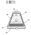
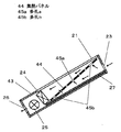
図4は本発明の実施例2の太陽熱集熱装置の構成図である。図4において、38は集熱パネルであり、空気入口側の巾(W1)より空気出口側の巾(W2)を大きくする構成である。39は集熱ユニットであり、集熱パネル38を収納する形態である。
【0021】
以上の構成において、その動作、作用について説明する。集熱パネル38に沿って流れる空気が下流になるにつれて温度上昇する。その結果、空気の比体積が大きく。それに対して、集熱パネル38の巾が下流側になるにつれて大きくなっているため、空気通路面積が大きくなって空気の通過風速が低下する。そのため、通風抵抗の増加が防止でき、送風手段の省電力化を実現する。
【0022】
そして、空気熱交換器へ近づくにつれて太陽熱の受熱面を大きくして空気を昇温するため集熱ユニットから外気への放熱ロスが少なく、高効率化を実現する。
【0023】
また、集熱ユニットと集熱パネルの空間距離を小さくして集熱パネル表面の温度境界層を少なくするように最適距離に保持して集熱パネルと空気の熱交換効率を高めることができる。それによって、集熱ユニットの薄型化が実現する。
【0024】
また、入口側の巾W1から出口側の巾W2へ連続的に拡大する構成にすれば、空気流れの縮流などが発生しないため、音、通路抵抗はさらに低減する。
【0025】
(参考例1)
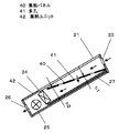
図5は本発明の参考例1の太陽熱集熱装置の構成図である。図5において、40は集熱パネルであり、多孔41が設けられている。42は集熱ユニットであり、集熱パネル40を集熱ユニット42内に傾斜して、空気吸込み部23と空気熱交換器24を間仕切り、空気吸込み部23から多孔41、空気熱交換器24と空気が流れるようにして、集熱パネル40から空気熱交換器24へ流れる方向に次第に空気通路面積を大きくするようにした構成したものであり、集熱パネル40と集熱ユニット42裏側の距離を入口側h1より、出口側h2を大きくする。
【0026】
以上の構成において、その動作、作用について説明する。空気吸込み部23から流入した空気が集熱パネル40の一面から集熱し、集熱パネル40の多孔41を通過して集熱パネル40の他方の面側へ流れ出る。そして、多孔41を通過する際に集熱パネル40から熱を奪い温度上昇する。そして、集熱パネル40の他方の面側へ流れ出た空気が集熱パネル40に沿って流れ、温度上昇しながら空気熱交換器24へ流れる。その際に、温度上昇にともない空気の比体積が増大する。しかし、空気熱交換器24へ流れるにつれて空気通路面積が増大するため通風風速が少なくなり、通風抵抗の増加を抑制する。従って、送風手段の省電力化を達成する。そして、集熱ユニット42の高さおよび巾のサイズを一定にして送風手段の省電力化を実現できる効果がある。
【0027】
(参考例2)
図6は本発明の参考例2の太陽熱集熱装置の構成図である。図6において、43は集熱ユニットであり、集熱パネル40を集熱ユニット43内に傾斜して、空気吸込み部23と空気熱交換器24を間仕切り、空気吸込み部23を透過体21と反対側にあたる集熱パネル40の裏面側に設け、空気吸込み部23、集熱パネル40の裏面側、多孔41、集熱パネル40の表面側、空気熱交換器24と空気が流れるようにする。そして、集熱パネル40の表面側の空気通路面積を空気熱交換器24へ流れるにつれて次第に大きくなるように構成したものであり、集熱パネル40と集熱ユニット43の透過体21の距離を入口側h1より、出口側h2を大きくする。
【0028】
以上の構成において、その動作、作用について説明する。集熱パネル40の裏面側の空気吸込み部23から流入した空気が多孔41を通過して集熱パネル40の表面側へ流れ出る。そして、多孔41を通過する際に集熱パネル40から熱を奪い温度上昇する。そして、集熱パネル40の表面側へ流れ出た空気が集熱パネル40の表面側に沿って流れ、太陽照射熱を受けながら高温まで温度上昇して空気熱交換器24へ流れる。その際に、温度上昇にともない空気の比体積が増大する。しかし、空気熱交換器24側へ流れるにつれて空気通路面積が増大するため通過風速が少なくなり、通風抵抗の増加を抑制する。従って、送風手段の省電力化を達成するとともに高温風を実現する。
【0029】
(参考例3)
図7は本発明の参考例3の太陽熱集熱装置の構成図である。図7において、44は集熱パネルであり、中央部の多孔45aの通過面積より空気吸込み部23近傍および空気熱交換器24側の多孔45aの通過面積を大きくする、あるいは1つの多孔面積を同じにして多孔45a間の孔ピッチを小さくする構成である。
【0030】
以上の構成において、その動作、作用について説明する。空気吸込み部23から流入した空気が集熱パネル44の一面から多孔45aを通過して集熱パネル44の他方の面側へ流れ出る際、集熱パネル44の一面に沿って流れる空気の空気通路面積が下流になるにつれて、すなわち空気熱交換器24へ近づくにつれてしだいに小さくなる。一方、集熱パネル44の他方の面側の空気通路面積は空気吸込み部23側が小さくて空気熱交換器24側が大きくなる。そのため、集熱パネル44の空気吸込み部23近傍および空気熱交換器24近傍の多孔45bを通過する空気量が少なく、集熱パネル44の中央部の多孔45aを通って他面側へ流れやすくなる。
【0031】
そのため、通過する空気は中央の多孔45aに集中するため、流路抵抗が増加する。しかし、空気吸込み部23近傍および空気熱交換器24側の多孔45bの通過面積を大きくして抵抗を少なくした構成であるため、集熱パネル44の空気吸込み部23近傍および空気熱交換器24近傍の多孔45bを空気が通過しやすくなり、集熱パネル44の多孔を通過する空気量が多孔45aと多孔45bで均一になるため流路抵抗が減少する。従って、送風手段の省電力化を実現する。
【0032】
【発明の効果】
以上のように、請求項1に記載の発明によれば、集熱パネルに沿って流れる高温空気の空気流路抵抗の増加を防止して、送風手段の省電力化をはかることができる。
【図面の簡単な説明】
【図1】 本発明の実施例1の太陽熱集熱装置の構成図
【図2】 本発明の実施例1の太陽熱集熱装置を用いた暖房装置の構成図
【図3】 本発明の実施例1の太陽熱集熱装置を用いた給湯装置の構成図
【図4】 本発明の実施例2の太陽熱集熱装置の構成図
【図5】 本発明の参考例1の太陽熱集熱装置の構成図
【図6】 本発明の参考例2の太陽熱集熱装置の構成図
【図7】 本発明の参考例3の太陽熱集熱装置の構成図
【図8】 従来の太陽熱集熱装置の構成図
【符号の説明】
20、38、40、44 集熱パネル
21 透過体
22、39、42、43 集熱ユニット
23 空気吸込み部
24 空気熱交換器
25 送風手段
26 空気吐出部
27 保温材
28、37 ヒートポンプ装置
29 圧縮機
30 凝縮器
31 減圧手段
32 貯湯槽
33 循環ポンプ
34 給湯熱交換器
35 給湯回路
36 室内器
41、45a、45b 多孔[0001]
BACKGROUND OF THE INVENTION
The present invention relates to a solar heat collecting apparatus that collects solar heat and uses it for hot water supply and heating.
[0002]
[Prior art]
Conventionally, as this type of heat pump device using solar heat, there has been one as described in Japanese Patent Application Laid-Open No. 59-15778, for example. FIG. 8 shows a conventional solar heat utilization device described in the publication.
[0003]
In FIG. 8, 1 is an outer box, 2 is a transparent plate, 6 is a heat collecting plate arranged so as to partition the inside of the outer box 1 into a front side and a back side, 8 is an outside air inlet, and 9 is flowing on the front side of the
[0004]
[Problems to be solved by the invention]
However, in the conventional configuration, low temperature air taken in from the outside air is flowed to the front side of the heat collecting plate 9 to gradually raise the temperature, and the heated air is returned to flow to the back side of the heat collecting plate 9. Yes. However, since the air flowing along the heat collecting plate 9 becomes higher in temperature as it approaches the downstream outlet, the specific volume increases. And since the heat collecting plate 9 is reciprocated from the front side to the back side, the air flow path becomes long. For this reason, the air flow path resistance increases, and the necessary air volume cannot be obtained, so that the heat exchange amount in the
[0005]
The present invention solves the above-described conventional problems, and the air passage area surrounded by the heat collection unit and the heat collection panel is gradually increased on the outlet side downstream of the heat collection panel inlet side on the air suction side. Thus, a solar heat collecting apparatus that dramatically reduces ventilation resistance and saves power in the blowing means is provided.
[0006]
[Means for Solving the Problems]
In order to solve the conventional problems, a solar heat collecting apparatus of the present invention includes a heat collecting panel that collects solar heat, a transmissive body that transmits sunlight to at least the heat collecting panel, and the transmissive body on a surface. A heat collection unit that houses the heat collection panel, an air suction part that introduces air into the heat collection unit, an air heat exchanger through which air passing through the heat collection panel flows, and the air suction part, The heat collection panel and the air heat exchanger in order, and air blowing means for conveying air, and by increasing the width of the heat collection panel on the outlet side from the heat collection panel inlet side on the air suction side, The area of the air passage surrounded by the unit and the heat collection panel is configured to gradually increase from the heat collection panel inlet side on the air suction side to the downstream outlet side . As a result, the air passage area is increased as it approaches the outlet of the heat collecting panel, and the air passage wind speed of high-temperature air is reduced, thereby preventing an increase in air flow path resistance.
[0007]
DETAILED DESCRIPTION OF THE INVENTION
The invention according to claim 1 is a heat collection panel that collects solar heat, a transmission body that transmits sunlight to at least the heat collection panel, the transmission body on the surface, and a heat collection panel that houses the heat collection panel. A unit, an air suction portion for introducing air into the heat collection unit, an air heat exchanger through which air passing through the heat collection panel flows, the air suction portion, the heat collection panel, and the air heat exchanger and a blower means to the conveying air in order, by increasing the width of the heat collection panel outlet side of the heat collection panel inlet side of the air suction side, surrounded by the heat collector panel and the heat collector air passage area is configured so as to be gradually increased from the heat collection panel inlet side of the air suction side to the downstream of the outlet side, to increase the air passage area toward the heat collection panel outlet, the air passage of hot air Reduce the wind speed, To prevent the increase in the air flow passage resistance, and realizes a power saving of the blowing means.
[0008]
【Example】
Embodiments of the present invention will be described below with reference to the drawings. In addition, in a prior art example and each Example, the same code | symbol is attached | subjected about what has the same structure and the same operation | movement, and description is partially abbreviate | omitted.
[0009]
Example 1
FIG. 1 shows a configuration diagram of a solar heat collecting apparatus according to a first embodiment of the present invention. FIG. 2 is a block diagram of a hot water supply apparatus using the solar heat collector, and FIG. 3 is a block diagram of a heating apparatus using the solar heat collector. 1, 2, and 3, the solid arrow indicates the air flow direction, the broken arrow indicates the refrigerant flow direction of the heat pump apparatus, and the alternate long and short dash line arrow indicates the water flow direction.
[0010]
In FIG. 1, 20 is a heat collection panel, and collects solar heat.
[0011]
In the configuration in which air flows on both the front and back surfaces of the
[0012]
In FIG. 2, 28 is a heat pump device, and the
[0013]
About the solar heat collecting device comprised as mentioned above, the operation | movement and an effect | action are demonstrated below. In FIG. 1, the air flowing in from the
[0014]
In this operation, the temperature of the air flowing along the
[0015]
In addition, the air flows through both the front and back surfaces of the
[0016]
Next, a hot water supply apparatus using this solar heat collector will be described. In FIG. 2, heat collected from the
[0017]
Then, the hot water in the hot
[0018]
Next, a heating device using this solar heat collecting device will be described. In FIG. 3, when the
[0019]
When this solar heat collecting device is used in connection with the heat pump device shown in FIGS. 2 and 3, the solar heat collecting device can be operated using atmospheric heat when the amount of solar solar radiation is small or in the rain. During the operation, the flow resistance of the air flowing through the
[0020]
(Example 2)
FIG. 4 is a configuration diagram of a solar heat collecting apparatus according to
[0021]
The operation and action of the above configuration will be described. The temperature rises as the air flowing along the
[0022]
And as it approaches the air heat exchanger, the heat receiving surface of the solar heat is enlarged to raise the temperature of the air, so that there is little heat loss from the heat collecting unit to the outside air, and high efficiency is realized.
[0023]
Further, the heat exchange efficiency between the heat collection panel and the air can be increased by maintaining the optimum distance so as to reduce the spatial distance between the heat collection unit and the heat collection panel to reduce the temperature boundary layer on the surface of the heat collection panel. As a result, the heat collecting unit can be made thinner.
[0024]
Further, if the configuration is such that the width W1 on the inlet side continuously expands to the width W2 on the outlet side, no contraction of the air flow occurs, so that the sound and passage resistance are further reduced.
[0025]
( Reference Example 1 )
FIG. 5 is a configuration diagram of the solar heat collecting apparatus of Reference Example 1 of the present invention. In FIG. 5,
[0026]
The operation and action of the above configuration will be described. The air flowing in from the
[0027]
( Reference Example 2 )
FIG. 6 is a configuration diagram of a solar heat collecting apparatus according to Reference Example 2 of the present invention. In FIG. 6,
[0028]
The operation and action of the above configuration will be described. The air flowing in from the
[0029]
( Reference Example 3 )
FIG. 7 is a configuration diagram of a solar heat collecting apparatus according to Reference Example 3 of the present invention. In FIG. 7,
[0030]
The operation and action of the above configuration will be described. The air passage area of the air flowing along one surface of the
[0031]
For this reason, the air passing therethrough is concentrated in the
[0032]
【The invention's effect】
As described above, according to the first aspect of the present invention, it is possible to prevent an increase in the air flow path resistance of the high-temperature air flowing along the heat collecting panel and to save power in the blowing means.
[Brief description of the drawings]
FIG. 1 is a block diagram of a solar heat collecting apparatus according to Embodiment 1 of the present invention. FIG. 2 is a block diagram of a heating apparatus using the solar heat collecting apparatus according to Embodiment 1 of the present invention. 1 is a block diagram of a hot water supply apparatus using the solar heat collector of FIG. 1. FIG. 4 is a block diagram of a solar heat collector of Example 2 of the present invention. FIG. 5 is a block diagram of a solar heat collector of Reference Example 1 of the present invention. FIG. 6 is a block diagram of a solar heat collector of Reference Example 2 of the present invention. FIG. 7 is a block diagram of a solar heat collector of Reference Example 3 of the present invention. FIG. 8 is a block diagram of a conventional solar heat collector. Explanation of symbols]
20, 38, 40, 44
Claims (1)
Priority Applications (1)
| Application Number | Priority Date | Filing Date | Title |
|---|---|---|---|
| JP2001149071A JP4517536B2 (en) | 2001-05-18 | 2001-05-18 | Solar heat collector |
Applications Claiming Priority (1)
| Application Number | Priority Date | Filing Date | Title |
|---|---|---|---|
| JP2001149071A JP4517536B2 (en) | 2001-05-18 | 2001-05-18 | Solar heat collector |
Publications (2)
| Publication Number | Publication Date |
|---|---|
| JP2002340421A JP2002340421A (en) | 2002-11-27 |
| JP4517536B2 true JP4517536B2 (en) | 2010-08-04 |
Family
ID=18994287
Family Applications (1)
| Application Number | Title | Priority Date | Filing Date |
|---|---|---|---|
| JP2001149071A Expired - Fee Related JP4517536B2 (en) | 2001-05-18 | 2001-05-18 | Solar heat collector |
Country Status (1)
| Country | Link |
|---|---|
| JP (1) | JP4517536B2 (en) |
Families Citing this family (4)
| Publication number | Priority date | Publication date | Assignee | Title |
|---|---|---|---|---|
| JP4618632B2 (en) * | 2004-07-21 | 2011-01-26 | 株式会社竹中工務店 | Heat collection duct and ventilation system using heat collection duct |
| CN105276870A (en) * | 2015-11-10 | 2016-01-27 | 东北电力大学 | Air cooling evaporator with solar heat collection function |
| CN110094813B (en) * | 2019-05-28 | 2024-07-16 | 浙江工业大学 | A variable solar air purifier |
| CN119196942A (en) * | 2024-10-28 | 2024-12-27 | 广东纽恩泰新能源科技股份有限公司 | Hot air device and control method for range-extended heat pump |
Family Cites Families (2)
| Publication number | Priority date | Publication date | Assignee | Title |
|---|---|---|---|---|
| JPS5621175U (en) * | 1979-07-26 | 1981-02-25 | ||
| JPS60235950A (en) * | 1984-05-08 | 1985-11-22 | Naoji Isshiki | Solar heat collecting device by permeable thin film |
-
2001
- 2001-05-18 JP JP2001149071A patent/JP4517536B2/en not_active Expired - Fee Related
Also Published As
| Publication number | Publication date |
|---|---|
| JP2002340421A (en) | 2002-11-27 |
Similar Documents
| Publication | Publication Date | Title |
|---|---|---|
| CN102401519B (en) | The off-premises station of air-conditioner | |
| CN213020380U (en) | A kind of air conditioning system and energy storage system for energy storage equipment | |
| CN110631268B (en) | Vacuum heat collection and storage type air source heat pump | |
| JP4517536B2 (en) | Solar heat collector | |
| CN211526570U (en) | An outdoor unit and a composite heat pump system | |
| CN218348953U (en) | Refrigerator with a door | |
| CN114899529A (en) | An energy-saving air conditioning cooling system | |
| CN212108744U (en) | Air conditioner outdoor unit | |
| CN218600008U (en) | Take air source heat pump hot water integral type device of cold volume utilization | |
| CN116293948A (en) | An air source intake structure | |
| CN217274511U (en) | Mobile air conditioner | |
| JP2002139254A (en) | Solar heat collector and heat pump device using the same | |
| CN210463578U (en) | Multifunctional energy-saving heat pump | |
| CN201146659Y (en) | Water-cooled heat dissipation system | |
| CN222086368U (en) | Refrigerator with a refrigerator body | |
| CN219346786U (en) | Hot water unit for inhibiting frosting | |
| CN208042559U (en) | A kind of high-efficiency air source heat pump device | |
| CN208222909U (en) | Sea water source heat pump trilogy supply unit and system | |
| CN221611509U (en) | Industrial air conditioner for high-energy-efficiency energy storage | |
| JP2002162109A (en) | Hot water supply system | |
| CN223425349U (en) | air conditioner | |
| CN221698428U (en) | Air conditioning system of extended range electric automobile and extended range electric automobile | |
| CN221944524U (en) | A high-efficiency air source heat pump unit | |
| CN221375996U (en) | A heat recovery trigeneration system | |
| CN222824471U (en) | A control panel heat dissipation device for an air conditioner outdoor unit |
Legal Events
| Date | Code | Title | Description |
|---|---|---|---|
| A621 | Written request for application examination |
Free format text: JAPANESE INTERMEDIATE CODE: A621 Effective date: 20080219 |
|
| RD01 | Notification of change of attorney |
Free format text: JAPANESE INTERMEDIATE CODE: A7421 Effective date: 20080312 |
|
| A977 | Report on retrieval |
Free format text: JAPANESE INTERMEDIATE CODE: A971007 Effective date: 20090225 |
|
| A131 | Notification of reasons for refusal |
Free format text: JAPANESE INTERMEDIATE CODE: A131 Effective date: 20091027 |
|
| RD01 | Notification of change of attorney |
Free format text: JAPANESE INTERMEDIATE CODE: A7421 Effective date: 20091119 |
|
| A521 | Request for written amendment filed |
Free format text: JAPANESE INTERMEDIATE CODE: A523 Effective date: 20091126 |
|
| TRDD | Decision of grant or rejection written | ||
| A01 | Written decision to grant a patent or to grant a registration (utility model) |
Free format text: JAPANESE INTERMEDIATE CODE: A01 Effective date: 20100427 |
|
| A01 | Written decision to grant a patent or to grant a registration (utility model) |
Free format text: JAPANESE INTERMEDIATE CODE: A01 |
|
| A61 | First payment of annual fees (during grant procedure) |
Free format text: JAPANESE INTERMEDIATE CODE: A61 Effective date: 20100510 |
|
| FPAY | Renewal fee payment (event date is renewal date of database) |
Free format text: PAYMENT UNTIL: 20130528 Year of fee payment: 3 |
|
| LAPS | Cancellation because of no payment of annual fees |