JP4522112B2 - Building fence - Google Patents

Building fence Download PDF

Info

Publication number
JP4522112B2
JP4522112B2 JP2004066453A JP2004066453A JP4522112B2 JP 4522112 B2 JP4522112 B2 JP 4522112B2 JP 2004066453 A JP2004066453 A JP 2004066453A JP 2004066453 A JP2004066453 A JP 2004066453A JP 4522112 B2 JP4522112 B2 JP 4522112B2
Authority
JP
Japan
Prior art keywords
plate portion
panel
mounting member
bracket
top plate
Prior art date
Legal status (The legal status is an assumption and is not a legal conclusion. Google has not performed a legal analysis and makes no representation as to the accuracy of the status listed.)
Expired - Fee Related
Application number
JP2004066453A
Other languages
Japanese (ja)
Other versions
JP2005256317A (en
Inventor
彰 三宅
仁志 吉村
Current Assignee (The listed assignees may be inaccurate. Google has not performed a legal analysis and makes no representation or warranty as to the accuracy of the list.)
Daiken Co Ltd
Original Assignee
Daiken Co Ltd
Priority date (The priority date is an assumption and is not a legal conclusion. Google has not performed a legal analysis and makes no representation as to the accuracy of the date listed.)
Filing date
Publication date
Application filed by Daiken Co Ltd filed Critical Daiken Co Ltd
Priority to JP2004066453A priority Critical patent/JP4522112B2/en
Publication of JP2005256317A publication Critical patent/JP2005256317A/en
Application granted granted Critical
Publication of JP4522112B2 publication Critical patent/JP4522112B2/en
Anticipated expiration legal-status Critical
Expired - Fee Related legal-status Critical Current

Links

Images

Landscapes

  • Building Awnings And Sunshades (AREA)

Description

本発明は、建物の軒先などに直射日光や雨水などを遮るために取り付けられる建物用庇に関するものである。   The present invention relates to a building fence attached to a building eaves or the like to block direct sunlight, rainwater, or the like.

従来のこの種建物用庇としては、例えば特許文献1に開示されているように、軒内側端部を躯体固着面とし、軒外側端部に係合受構造を備えてなる基礎パネルと、軒内側端部に係合構造を設け、軒外側端部に係合受構造を備えてなる連結パネルと、軒内側端部に係合構造を備えてなる先端パネルとからなり、前記基礎パネルを躯体に固定し、この基礎パネルの軒外方向に係合構造と係合受構造とを係合することにより1又は2以上の連結パネル、若しくは先端パネルを連結し、連結パネルの軒外方向にはさらに係合構造と係合受構造とを係合することにより先端パネルを連結する構成を有する連結型庇が知られている。
特開2000−145078号公報
For example, as disclosed in Patent Document 1, for example, this type of conventional building eaves includes a base panel having an eaves inner end as a frame fixing surface and an eaves outer end provided with an engagement receiving structure, and eaves. The base panel comprises a connecting panel provided with an engagement structure at the inner end and an engagement receiving structure at the outer end of the eave, and a tip panel provided with an engagement structure at the inner end of the eave. 1 or 2 or more connecting panels or tip panels are connected by engaging the engagement structure and the engagement receiving structure in the direction of the eaves of the foundation panel. Further, a connecting type scissors having a configuration in which the front end panel is connected by engaging the engaging structure and the engaging receiving structure is known.
JP 2000-1405078 A

上記の特許文献1に開示されている連結型庇は基礎パネルと連結パネルと先端パネルとからなり、基礎パネルと連結パネルと先端パネルの全てがアルミの押出材から形成されていて、それぞれが一体構成となっており、前後方向の長さが長い庇にあっては、製造するための金型も大きいものが必要となり、コストが高くつくという問題があった。   The connection type scissors disclosed in the above-mentioned Patent Document 1 includes a base panel, a connection panel, and a tip panel, and all of the base panel, the connection panel, and the tip panel are formed of an extruded aluminum material. In the case of a kite having a long length in the front-rear direction, a large mold is required for manufacturing, and there is a problem that the cost is high.

本発明の目的は、このような課題を解決するものであり、全体をアルミの押出材から形成されている従来のものに比べて安価な建物用庇を提供することにある。   SUMMARY OF THE INVENTION An object of the present invention is to solve such problems and to provide a building fence that is cheaper than a conventional one that is formed entirely from an extruded aluminum material.

本発明の請求項1に記載の建物用庇は、庇取り付け壁面に取り付けられる壁取り付け部材と、この壁取り付け部材の下端と取り付け角度変更可能に係合するパネル取り付け用部材と、このパネル取り付け用部材に取り付けられるパネル部材と、このパネル部材の前端部に取り付けられる先端見切り部材とから構成されており、前記壁取り付け部材、パネル取り付け用部材および先端見切り部材はアルミの押出材により作られ、前記パネル部材は、アルミの板材を折り曲げて作られ、天板部と、天板部の後端に繋がる後板部と、後板部の下端に内側に折れ曲がるように繋がり天板部と平行で前後方向に短い第1の板部と、天板部の左右両側に繋がる側板部と、この側板部の下端に内側に折れ曲がるように繋がり天板部と平行で左右方向に短い第2の板部とを備えるパネル本体と、第2の板部と第2の板部の上方に位置する第1の板部との間に差し込まれる底板とから構成されている建物用庇であって、パネル部材の前端部に先端見切り部材の後端部の爪片を係合させる溝部を有するようにアルミの押出材により作られたブラケットを配設し、パネル本体の後板部とブラケットを前後方向に貫通する長軸のボルトの頭部をパネル取り付け用部材の前端部において形成された凹溝に嵌合するとともにブラケットから前方に突出するボルトの先端にナットを螺合させ締め付けることによりパネル部材をブラケットと一体的にパネル取り付け用部材に結合させるように構成し、パネル部材の内部には前後方向に向いてパネル本体の反りを防止する補強材を設けてあることを特徴とする。 The building fence according to claim 1 of the present invention is a wall mounting member attached to the wall mounting wall, a panel mounting member engaged with the lower end of the wall mounting member so that the mounting angle can be changed, and the panel mounting A panel member attached to the member, and a tip parting member attached to the front end of the panel member, and the wall attaching member, the panel attaching member and the tip parting member are made of an aluminum extruded material, The panel member is made by bending an aluminum plate , connected to the top plate, the rear plate connected to the rear end of the top plate, and the lower end of the rear plate so as to be bent inward and back and forth in parallel with the top plate. A first plate portion that is short in the direction, a side plate portion that is connected to both the left and right sides of the top plate portion, a second plate that is connected to the lower end of the side plate portion so as to be bent inward, and is short in the left-right direction in parallel with the top plate portion. A panel body and a plate portion of a first eaves for buildings is composed of a bottom plate which is inserted between the plate portion located above the second plate portion and the second plate portion The bracket made of aluminum extrusion material is arranged so that the front end of the panel member has a groove that engages the claw piece of the rear end of the front end parting member, and the rear plate portion of the panel body and the bracket are The head of a long-axis bolt that penetrates in the direction is fitted into a recessed groove formed at the front end of the panel mounting member, and a nut is screwed onto the tip of the bolt protruding forward from the bracket and tightened to tighten the panel member And the bracket is integrally coupled to the panel mounting member, and a reinforcing member is provided inside the panel member to prevent warping of the panel body in the front-rear direction.

以上のように、本発明の建物用庇は、全体をアルミの押出材から形成されているのではなく、最も大きな面積を占めるパネル部材はアルミの板材を折り曲げて作られ、天板部と、天板部の後端に繋がる後板部と、後板部の下端に内側に折れ曲がるように繋がり天板部と平行で前後方向に短い第1の板部と、天板部の左右両側に繋がる側板部と、この側板部の下端に内側に折れ曲がるように繋がり天板部と平行で左右方向に短い第2の板部とを備えるパネル本体と、第2の板部と第2の板部の上方に位置する第1の板部との間に差し込まれる底板とから構成されているので、制作費が押出材で作ったものに比べ安価になる。 As described above, the building fence of the present invention is not formed entirely of an aluminum extruded material, but the panel member occupying the largest area is made by bending an aluminum plate material , A rear plate portion connected to the rear end of the top plate portion, a first plate portion that is connected to bend inward at the lower end of the rear plate portion, is parallel to the top plate portion, and is short in the front-rear direction, and is connected to the left and right sides of the top plate portion. A panel body comprising a side plate portion and a second plate portion that is connected to the lower end of the side plate portion so as to be bent inward and is parallel to the top plate portion and short in the left-right direction ; and the second plate portion and the second plate portion Since it is comprised from the bottom plate inserted between the 1st board parts located upwards , production cost becomes cheap compared with what was made with the extrusion material.

以下、本発明の一実施の形態を、図1〜図12に基づいて説明する。
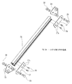
図において、本実施の形態の建物用庇1は、建物における庇取り付け壁面2に取り付けられる壁取り付け部材3と、この壁取り付け部材3の下端と取り付け角度変更可能に係合するパネル取り付け用部材4と、このパネル取り付け用部材4に取り付けられるパネル部材5と、このパネル部材5の前端部に取り付けられる先端見切り部材6とから構成されている。
Hereinafter, an embodiment of the present invention will be described with reference to FIGS.
In the figure, a building fence 1 according to the present embodiment includes a wall attachment member 3 attached to a fence attachment wall surface 2 in the building, and a panel attachment member 4 engaged with the lower end of the wall attachment member 3 so that the attachment angle can be changed. And a panel member 5 attached to the panel attachment member 4 and a tip parting member 6 attached to the front end portion of the panel member 5.

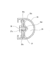
前記壁取り付け部材3はアルミの押出材から形成され、壁面2に沿う鉛直部分3aと、この鉛直部分3aの上端より壁面2前方に突出するように形成された下向き円弧状の突出部分3bと、この突出部分3bの先端部ならびに前後方向中央部裏面に突出するように形成されたリブ3c,3dと、前記鉛直部分3aの下端に形成されたパネル取り付け用部材4との係合部3eとを備え、前記鉛直部分3aを壁面2に対し壁面2に埋設したアンカーボルト7にナット8を螺合させることにより取り付けるように構成されている。なお、鉛直部分3aの上端には凹状の段部3fが形成されてあり、この段部3fと前記壁面2との間にパッキン9が介在されるようになっている。また、この壁取り付け部材3の両側端には側板10が前記突出部分3bの先端部のリブ3cと、係合部3eと、鉛直部分3aと突出部分3bとの繋がり部に形成されたタッピング孔3gの位置でビス11止めされて取り付けられている。さらに、この壁取り付け部材3の横長さ方向複数箇所において鉛直部分3aには前記係合部3eのやや上側において前記パネル取り付け用部材4の外れ防止用の支持金具12が鉛直部分3aに対しボルト(図示せず)により取り付けられている。   The wall mounting member 3 is formed of an extruded material of aluminum, a vertical portion 3a along the wall surface 2, and a downward arcuate protruding portion 3b formed to protrude forward from the upper end of the vertical portion 3a to the wall surface 2, The ribs 3c and 3d formed so as to protrude from the front end portion of the protruding portion 3b and the back of the central portion in the front-rear direction, and the engaging portion 3e between the panel mounting member 4 formed at the lower end of the vertical portion 3a. And the vertical portion 3a is attached to the wall surface 2 by screwing a nut 8 to an anchor bolt 7 embedded in the wall surface 2. A concave step 3 f is formed at the upper end of the vertical portion 3 a, and a packing 9 is interposed between the step 3 f and the wall surface 2. In addition, the side plate 10 is tapped holes formed in the connecting portion between the rib 3c at the tip of the protruding portion 3b, the engaging portion 3e, and the vertical portion 3a and the protruding portion 3b at both side ends of the wall mounting member 3. Screws 11 are fixed and attached at a position of 3 g. Further, at a plurality of positions in the lateral direction of the wall mounting member 3, the vertical portion 3a has a support bracket 12 for preventing the panel mounting member 4 from coming off slightly above the engaging portion 3e with respect to the vertical portion 3a. (Not shown).

前記パネル取り付け用部材4もアルミの押出材から形成され、下端の扁平な板部4aと、この板部4aの後端部に形成され前記壁取り付け部材3の係合部3eに係合する係合部4bと、前記壁取り付け部材3の下向き円弧状の突出部分3bの円弧に沿うように前記板部4aの上方で円弧状に形成された板部4cと、この板部4cの前端部に繋がり前記板部4aと平行で前端部が板部4aの前端部に揃う板部4dと、係合部4bの付け根部分から斜め前方に傾斜して立ち上がり前記板部4aと板部4cとを繋ぐ支持部4eと、前記板部4a,4d間に形成された凹溝4fとを備えている。なお、このパネル取り付け用部材4の両側端には側板14が前記板部4cの後端部および凹溝4fの外面に形成されたタッピング孔4gの位置でビス15止めされて取り付けられている。そして、このパネル取り付け用部材4は前記係合部4bが壁取り付け部材3の係合部3eに前方から係合されるのであるが、その際前記支持金具12のボルトによる締め付けは緩められており、図9に示すようにパネル取り付け用部材4を下に向かせて前記壁取り付け部材3の突出部分3bの前端部とパネル取り付け用部材4の板部4cの後端部との間に正面に開口する隙間を形成した状態で両係合部4b,3eの係合を確認した上でボルトが締め付けられることにより支持金具12によってパネル取り付け用部材4の外れ防止を行なうようになっている。   The panel mounting member 4 is also formed of an aluminum extruded material, and is a flat plate portion 4a at the lower end and a engagement portion 3e formed at the rear end portion of the plate portion 4a and engaged with the engaging portion 3e of the wall mounting member 3. A joint portion 4b, a plate portion 4c formed in an arc shape above the plate portion 4a along the arc of the downward arcuate projecting portion 3b of the wall mounting member 3, and a front end portion of the plate portion 4c A plate portion 4d parallel to the plate portion 4a and having a front end aligned with the front end portion of the plate portion 4a, and rises obliquely forward from the base portion of the engaging portion 4b to connect the plate portion 4a and the plate portion 4c. A support portion 4e and a concave groove 4f formed between the plate portions 4a and 4d are provided. A side plate 14 is attached to both side ends of the panel mounting member 4 with screws 15 fixed at the positions of the rear end portion of the plate portion 4c and the tapping hole 4g formed in the outer surface of the concave groove 4f. In this panel mounting member 4, the engaging portion 4b is engaged with the engaging portion 3e of the wall mounting member 3 from the front. At this time, tightening of the support fitting 12 with bolts is loosened. As shown in FIG. 9, the panel mounting member 4 is directed downward, and the front surface of the protruding portion 3 b of the wall mounting member 3 and the rear end of the plate portion 4 c of the panel mounting member 4 are faced to the front. The bolts are tightened after confirming the engagement of both the engaging portions 4b and 3e in the state where the opening gap is formed, thereby preventing the panel mounting member 4 from being detached by the support fitting 12.

前記パネル部材5は押出しにより作られるものではなく、アルミの板材を折り曲げて作られたパネル本体16と、このパネル本体16の下端を塞ぐために表裏両面がアルミ箔で覆われた合成樹脂製の底板17とから構成されている。詳しくは、パネル本体16は天板部16aと、この天板部16aの後端に繋がる後板部16bと、この後板部16bの下端に内側に折れ曲がるように繋がり天板部16aと平行で前後方向に短い板部16cと、前記天板部16aの左右両端に繋がる側板部16dと、この側板部16dの下端に内側に折れ曲がるように繋がり天板部16aと平行で左右方向に短い板部16eとを備えており、この板部16eとこの板部16eの上方に位置する前記板部16cとの間に前記底板17が差し込まれる程度の間隙が形成されている。このパネル部材5は後端部が前記パネル取り付け用部材4の板部4a,4dの前端部に嵌め込まれるのであるが、そのとき天板部16aが前記パネル取り付け用部材4の板部4dの内面に当接するように嵌め込まれる。その状態において前記板部16cとパネル取り付け用部材4の板部4aとの間には前記底板17が差し込まれる程度の間隙が形成される。   The panel member 5 is not made by extrusion, but a panel body 16 made by bending an aluminum plate, and a bottom plate made of synthetic resin whose front and back surfaces are covered with aluminum foil in order to close the lower end of the panel body 16 17. Specifically, the panel body 16 is connected to the top plate portion 16a, the rear plate portion 16b connected to the rear end of the top plate portion 16a, and the lower end of the rear plate portion 16b so as to be bent inward, and is parallel to the top plate portion 16a. A plate portion 16c that is short in the front-rear direction, a side plate portion 16d that is connected to the left and right ends of the top plate portion 16a, and a plate portion that is connected to be bent inward at the lower end of the side plate portion 16d and that is parallel to the top plate portion 16a and short in the left-right direction. 16e, and a gap that allows the bottom plate 17 to be inserted is formed between the plate portion 16e and the plate portion 16c located above the plate portion 16e. The panel member 5 has a rear end portion fitted into the front end portions of the plate portions 4 a and 4 d of the panel mounting member 4. At that time, the top plate portion 16 a is an inner surface of the plate portion 4 d of the panel mounting member 4. It is fitted so as to abut. In this state, a gap is formed between the plate portion 16c and the plate portion 4a of the panel mounting member 4 so that the bottom plate 17 is inserted.

前記パネル部材5の前端部に先端見切り部材6を取り付けるためにパネル部材5の前端部にはブラケット18が取り付けられる。このブラケット18もアルミの押出材から形成され、パネル部材5の天板部16aと底板17との前端部の開口を塞ぐための板部18aと、この板部18aの上下両端に繋がり互いに平行で前記天板部16aと底板17との間に嵌り込む板部18b,18bと、板部18aと板部18b,18bとの繋がり部近傍において上下に突出して前記天板部16aと底板17の前端部に当接するように設けられた突出片18c,18dと、この突出片18c,18dの直ぐ前において板部18aと板部18bとの繋がり部近傍に形成され溝部18e,18fとから構成されている。   A bracket 18 is attached to the front end portion of the panel member 5 in order to attach the front end parting member 6 to the front end portion of the panel member 5. The bracket 18 is also formed of an extruded material of aluminum, and is connected to a plate portion 18a for closing the opening of the front end portion of the top plate portion 16a and the bottom plate 17 of the panel member 5, and to the upper and lower ends of the plate portion 18a so as to be parallel to each other The front ends of the top plate portion 16a and the bottom plate 17 project upward and downward in the vicinity of the plate portions 18b and 18b fitted between the top plate portion 16a and the bottom plate 17 and the connection portions of the plate portions 18a and 18b and 18b. Projecting pieces 18c, 18d provided so as to abut against the portion, and groove portions 18e, 18f formed in the vicinity of the connecting portion between the plate portion 18a and the plate portion 18b immediately before the projecting pieces 18c, 18d. Yes.

前記先端見切り部材6もアルミの押出材から形成され、上下の板部を先端部の円弧状部分で繋いだ形状を呈し、後端部には前記ブラケット18の溝部18e,18fに係合する爪片6a,6bを備えている。なお、この先端見切り部材6の下側の爪片6bからは前記ブラケット18の板部18aの下端に繋がる板部18bとの間で前記パネル部材5の前記底板17が差し込まれる程度の間隙を形成するための受け片6cが後方に延設されている。また、先端見切り部材6の両側端には側板19が先端部の円弧状部分の内側に形成されたタッピング孔6dの位置でビス20止めされて取り付けられている。   The tip parting member 6 is also formed of an aluminum extruded material, has a shape in which upper and lower plate portions are connected by an arcuate portion of the tip portion, and a claw that engages with the groove portions 18e and 18f of the bracket 18 at the rear end portion. The pieces 6a and 6b are provided. A gap is formed between the lower claw piece 6b on the lower end part 6 and the plate 18b connected to the lower end of the plate 18a of the bracket 18 so that the bottom plate 17 of the panel member 5 is inserted. The receiving piece 6c for extending is extended back. Further, side plates 19 are attached to both ends of the tip parting member 6 with screws 20 fixed at the positions of tapping holes 6d formed inside the arcuate portion of the tip portion.

前記パネル部材5の天板部16aと底板17との間にブラケット18の板部18b,18bを嵌めた状態において前記パネル部材5の後端部を前記パネル取り付け用部材4の板部4a,4dの前端部に嵌め込むとともに、前記パネル取り付け用部材4の凹溝4fに頭部21aが嵌合されている長軸のボルト21をパネル部材5の後板部16bおよびブラケット18の板部18aを前後方向に貫通させ、ブラケット18の板部18aから前方に突出するボルト21の先端にナット22を螺合させ締め付けることによりパネル部材5はブラケット18と一体的にパネル取り付け用部材4に結合されることになる。なお、前記パネル部材5の天板部16aとこの天板部16aに当接するブラケット18の板部18bとはビス13により固定されている。前記先端見切り部材6はパネル部材5をブラケット18と一体的にパネル取り付け用部材4に結合した後でブラケット18の溝部18e,18fに爪片6a,6bを係合させることにより取り付けられ、その後で両側端に前記側板19が取り付けられる。   In a state where the plate portions 18 b and 18 b of the bracket 18 are fitted between the top plate portion 16 a and the bottom plate 17 of the panel member 5, the rear end portion of the panel member 5 is connected to the plate portions 4 a and 4 d of the panel mounting member 4. The long bolt 21 having the head 21a fitted in the recessed groove 4f of the panel mounting member 4 is inserted into the rear plate portion 16b of the panel member 5 and the plate portion 18a of the bracket 18. The panel member 5 is joined to the panel mounting member 4 integrally with the bracket 18 by penetrating in the front-rear direction and screwing and tightening the nut 22 to the tip of the bolt 21 protruding forward from the plate portion 18a of the bracket 18. It will be. The top plate portion 16a of the panel member 5 and the plate portion 18b of the bracket 18 in contact with the top plate portion 16a are fixed by screws 13. The front end parting member 6 is attached by engaging the claw pieces 6a and 6b with the groove portions 18e and 18f of the bracket 18 after the panel member 5 is joined to the panel attaching member 4 integrally with the bracket 18, and thereafter. The side plate 19 is attached to both ends.

かかる構成により、パネル取り付け用部材4、パネル部材5、ブラケット18、先端見切り部材6は一体結合され、これらはパネル取り付け用部材4を基部として前記壁取り付け部材3に対し回動自在となる。   With this configuration, the panel mounting member 4, the panel member 5, the bracket 18, and the tip parting member 6 are integrally coupled, and these are rotatable with respect to the wall mounting member 3 with the panel mounting member 4 as a base.

建物用庇1は、建物における庇取り付け壁面2に取り付けられた工事完了状態において固定状態にしなければならず、建物用庇1の前後方向の長さが短い場合は前記壁取り付け部材3に対しパネル取り付け用部材4、パネル部材5、ブラケット18、先端見切り部材6の角度設定後、壁取り付け部材3の両側端の側板10とパネル取り付け用部材4の両側端の側板14とをビスにより結合させれば良いが、建物用庇1の前後方向の長さが長い場合は、前記パネル部材5の天板部16aの左右両側位置近傍における前端部近傍上面にステイ取り付け金具23を取り付け、このステイ取り付け金具23に対向するように庇取り付け壁面2にもステイ取り付け金具24を取り付け、前記壁取り付け部材3に対しパネル取り付け用部材4、パネル部材5、ブラケット18、先端見切り部材6の角度設定後、両ステイ取り付け金具23,24間をステイ25で繋ぎ、建物用庇1を支持すれば良い。   The building fence 1 must be fixed in the construction completion state attached to the wall mounting wall 2 in the building. When the length of the building fence 1 in the front-rear direction is short, it is a panel with respect to the wall mounting member 3. After setting the angles of the mounting member 4, the panel member 5, the bracket 18, and the tip parting member 6, the side plates 10 on both sides of the wall mounting member 3 and the side plates 14 on both sides of the panel mounting member 4 can be coupled with screws. However, if the length of the building basket 1 in the front-rear direction is long, the stay mounting bracket 23 is mounted on the upper surface in the vicinity of the front end portion in the vicinity of the left and right side positions of the top plate portion 16a of the panel member 5. A stay mounting bracket 24 is also mounted on the wall mounting wall 2 so as to face the wall 23, and a panel mounting member 4 and a panel member are attached to the wall mounting member 3. , The bracket 18, after the angle setting of the tip parting member 6, between the two stay mounting brackets 23, 24 connected by stays 25 may be supported the building eaves 1.

前記ステイ25は背面に溝26aが形成された中空状のステイ本体26と、このステイ本体26の長さ方向両端の溝26aに嵌入されステイ本体26にねじ止めされる2枚の連結板体27とから構成される。詳しくは、ステイ本体26の溝26aと中空部26bを仕切る板部26cに中空部26b側に向ってV状に突出するように凹状部26dが長さ方向に連続して形成され、連結板体27はねじ孔27aが形成され、ステイ本体26の長さ方向両端の溝26aに嵌入された連結板体27のねじ孔27aに螺合されるボルト28の先端を凹状部26dに食い込ませてステイ本体26に対して連結板体27を所望の位置で固定するように構成されている。そして、建物用庇1(パネル取り付け用部材4、パネル部材5、ブラケット18、先端見切り部材6)の取り付け角度に応じてステイ取り付け金具23,24間のステイ25の長さを調節するのであり、ステイ25とステイ取り付け金具23,24との間は連結板体27をステイ取り付け金具23,24に対しボルト29、ナット30により固定することにより行なうことができる。なお、このステイ25の構成は以上述べた実施の形態のものに限定されるものではない。   The stay 25 includes a hollow stay main body 26 having a groove 26 a formed on the back surface, and two connecting plate bodies 27 fitted into the grooves 26 a at both ends in the length direction of the stay main body 26 and screwed to the stay main body 26. It consists of. Specifically, a concave portion 26d is continuously formed in the length direction so as to protrude in a V shape toward the hollow portion 26b side on the plate portion 26c that partitions the groove 26a and the hollow portion 26b of the stay main body 26. 27, screw holes 27a are formed, and the ends of the bolts 28 screwed into the screw holes 27a of the connecting plate 27 fitted in the grooves 26a at both ends in the length direction of the stay body 26 are bitten into the concave portions 26d. The connecting plate 27 is fixed to the main body 26 at a desired position. Then, the length of the stay 25 between the stay mounting brackets 23 and 24 is adjusted according to the mounting angle of the building cage 1 (panel mounting member 4, panel member 5, bracket 18 and tip parting member 6). The stay 25 and the stay mounting brackets 23 and 24 can be connected by fixing the connecting plate 27 to the stay mounting brackets 23 and 24 with bolts 29 and nuts 30. The structure of the stay 25 is not limited to that of the above-described embodiment.

ところで、前記パネル部材5はパネル取り付け用部材4の凹溝4fに頭部21aが嵌合されている長軸のボルト21をパネル部材5の後板部16bおよびブラケット18の板部18aを前後方向に貫通させた状態で、ブラケット18の板部18aから前方に突出するボルト21の先端にナット22を螺合させ締め付けることによりブラケット18と一体的にパネル取り付け用部材4に結合されるのであるが、ナット22の締め付けによりパネル部材5の天板部16aに反りが発生するという問題が生じる場合がある。この現象はパネル部材5の前後長さが長い場合に顕著であり、この反りの発生を止めるためにパネル部材5の内部に前後方向に向いて第1および第2の補強材31A,31Bを設けるのが好ましい。この補強材31A,31Bは鉄製で、ボルト21の配設位置に設けられる。ボルト21による締結位置(本数)は建物用庇1の前後方向の長さや左右方向の長さによって決められ、前述のようなステイ25を用いない場合は図3に示すように底板部31aと、この底板部31aの両側から立ち上がる側板部31bを備えた断面形状が凵状の第1の補強材31Aを用い、ボルト21の配設位置において第1の補強材31Aで前記ボルト21を包むようにして第1の補強材31Aの長さ方向両端を前記パネル部材5の後板部16bおよびブラケット18の板部18aに近接させておくことによりパネル部材5の天板部16aの反りの発生を防止することができる。   By the way, the panel member 5 has a long-axis bolt 21 in which the head 21a is fitted in the concave groove 4f of the panel mounting member 4, the rear plate portion 16b of the panel member 5 and the plate portion 18a of the bracket 18 in the front-rear direction. In this state, the nut 22 is screwed onto the tip of the bolt 21 projecting forward from the plate portion 18a of the bracket 18 and tightened to be integrally coupled to the panel mounting member 4 with the bracket 18. There is a case where the top plate portion 16a of the panel member 5 is warped by tightening the nut 22. This phenomenon is remarkable when the front and rear length of the panel member 5 is long, and the first and second reinforcing members 31A and 31B are provided inside the panel member 5 in the front and rear direction in order to stop the warpage. Is preferred. The reinforcing members 31A and 31B are made of iron and are provided at the positions where the bolts 21 are disposed. The fastening position (number) of the bolts 21 is determined by the length in the front-rear direction and the length in the left-right direction of the building fence 1, and when the stay 25 as described above is not used, as shown in FIG. A first reinforcing member 31A having a hook-like cross-sectional shape provided with side plate portions 31b rising from both sides of the bottom plate portion 31a is used, and the bolt 21 is wrapped with the first reinforcing member 31A at the position where the bolt 21 is disposed. The warp of the top plate portion 16a of the panel member 5 can be prevented by keeping both longitudinal ends of the one reinforcing member 31A close to the rear plate portion 16b of the panel member 5 and the plate portion 18a of the bracket 18. Can do.

前記ステイ25を用いて建物用庇1を支持するものについては、パネル部材5の天板部16a上面に取り付けたステイ取り付け金具23の位置でボルト21による締結を行なうようにして、ステイ取り付け金具23の位置に存在しないボルト21による締結箇所においては前記図3に示すように底板部31aと、この底板部31aの両側から立ち上がる側板部31bを備えた断面形状が凵状の第1の補強材31Aを用いてパネル部材5の天板部16aの補強を行ない、ステイ取り付け金具23の位置に存在するボルト21による締結箇所においては図4に示すように底板部31aと、この底板部31aの両側から立ち上がる側板部31bと、一方の側板部31bの上端に一側辺が繋がり水平に張り出す上板部31cと、この上板部31cの他側辺から垂下する側板部31dを備えた第2の補強材31Bを用い、ステイ取り付け金具23の位置に存在するボルト21の配設位置において第2の補強材31Bの底板部31aと側板部31bとで前記ボルト21を包むようにして上板部31cを天板部16aを挟んでステイ取り付け金具23の下側に位置させ、ボルト32およびナット33によりステイ取り付け金具23と上板部31cを天板部16aに対して結合させ、第2の補強材31Bの長さ方向両端を前記パネル部材5の後板部16bおよびブラケット18の板部18aに近接させておくことによりパネル部材5の天板部16aの反りの発生を防止することができる。なお、第1および第2の補強材31A,31Bともにブラケット18の板部18aに近接する長さ方向一端においてブラケット18の板部18aの上端に繋がる板部18bとの当接を避けるために側板部31bの上端を切除してある。第2の補強材31Bにあっては上板部31cおよび側板部31dの一端をも切除してある。31eはその切除部である。   For the one that uses the stay 25 to support the building cage 1, the stay mounting bracket 23 is fastened by the bolt 21 at the position of the stay mounting bracket 23 that is mounted on the top surface 16 a of the panel member 5. As shown in FIG. 3, the first reinforcing member 31 </ b> A having a bowl-shaped cross section including a bottom plate portion 31 a and side plate portions 31 b rising from both sides of the bottom plate portion 31 a as shown in FIG. 3. 4 is used to reinforce the top plate portion 16a of the panel member 5. At the fastening position by the bolt 21 existing at the position of the stay mounting bracket 23, the bottom plate portion 31a and both sides of the bottom plate portion 31a are connected as shown in FIG. A side plate portion 31b that rises, an upper plate portion 31c that has one side connected to the upper end of one side plate portion 31b and projects horizontally, and other parts of the upper plate portion 31c. Using the second reinforcing member 31B provided with the side plate portion 31d depending from the side, the bottom plate portion 31a and the side plate portion 31b of the second reinforcing member 31B are provided at the position where the bolt 21 exists at the position of the stay mounting bracket 23. The upper plate portion 31c is positioned below the stay mounting bracket 23 with the top plate portion 16a interposed therebetween so as to wrap the bolt 21, and the stay mounting bracket 23 and the upper plate portion 31c are connected to the top plate portion 16a by the bolt 32 and the nut 33. And both ends in the length direction of the second reinforcing member 31B are brought close to the rear plate portion 16b of the panel member 5 and the plate portion 18a of the bracket 18 to thereby prevent the top plate portion 16a of the panel member 5 from being attached. Generation of warpage can be prevented. In addition, in order to avoid contact | abutting with the board part 18b connected to the upper end of the board part 18a of the bracket 18 in the length direction end close | similar to the board part 18a of the bracket 18 with 1st and 2nd reinforcement material 31A, 31B. The upper end of the part 31b is excised. In the second reinforcing material 31B, one end of the upper plate portion 31c and the side plate portion 31d is also cut off. 31e is the excision part.

以上のように本実施の形態の建物用庇1は全体をアルミの押出材から形成されているのではなく、最も大きな面積を占めるパネル部材5はアルミの板材を折り曲げて作られたパネル本体16と、このパネル本体16の下端を塞ぐ底板17とから構成されているので、製作費が押出材で作ったものに比べて安価になる。   As described above, the building basket 1 according to the present embodiment is not entirely formed of an aluminum extruded material, but the panel member 5 occupying the largest area is a panel body 16 made by bending an aluminum plate. And the bottom plate 17 that closes the lower end of the panel main body 16, the manufacturing cost is lower than that of the product made of the extruded material.

本発明の一実施の形態における建物用庇の分解斜視図である。It is a disassembled perspective view of the building fence in one embodiment of this invention. 同建物用庇に使用されるステイの分解斜視図である。It is a disassembled perspective view of the stay used for the cage for the building. 同建物用庇に使用される第1の補強材の斜視図である。It is a perspective view of the 1st reinforcement material used for the cage for the building. 同建物用庇に使用される第2の補強材の斜視図である。It is a perspective view of the 2nd reinforcement material used for the cage for the building. 同建物用庇の平面図である。It is a top view of the cage for the building. 同建物用庇の正面図である。It is a front view of the cage for the building. 同建物用庇の側面図である。It is a side view of the cage for the building. 図6のA−A断面図である。It is AA sectional drawing of FIG. 同建物用庇の取り付け工事途中の状態を示す側面断面図である。It is side surface sectional drawing which shows the state in the middle of attachment construction of the fence for the buildings. 同ステイとステイ取り付け金具との連結部の拡大斜視図である。It is an expansion perspective view of the connection part of the stay and a stay mounting bracket. 同ステイのステイ本体に対する連結板体の固定部の拡大断面図である。It is an expanded sectional view of the fixing | fixed part of the connection plate body with respect to the stay main body of the stay. 同ステイ取り付け金具と第2の補強材との結合状態を示す拡大断面図である。It is an expanded sectional view which shows the combined state of the stay attachment metal fitting and a 2nd reinforcement material.

符号の説明Explanation of symbols

1 建物用庇
2 庇取り付け壁面
3 壁取り付け部材
3a 鉛直部分
3b 突出部分
3c,3d リブ
3e 係合部
4 パネル取り付け用部材
4a 板部
4b 係合部
4c,4d 板部
4e 支持部
4f 凹溝
5 パネル部材
6 先端見切り部材
6a,6b 爪片
6c 受け片
7 アンカーボルト
8 ナット
10 側板
12 支持金具
14 側板
16 パネル本体
16a 天板部後板部
16b 後板部
16c 板部
16d 側板部
16e 板部
17 底板
18 ブラケット
18a,18b 板部
18c,18d 突出片
18e,18f 溝部
19 側板
21 ボルト
21a 頭部
22 ナット
23,24 ステイ取り付け金具
25 ステイ
31A 第1の補強材
31B 第2の補強材
31a 底板部
31b 側板部
31c 上板部
31d 側板部
31e 切除部
32 ボルト
33 ナット
DESCRIPTION OF SYMBOLS 1 Building fence 2 Wall mounting wall 3 Wall mounting member 3a Vertical part 3b Projection part 3c, 3d Rib 3e Engagement part 4 Panel attachment member 4a Plate part 4b Engagement part 4c, 4d Plate part 4e Support part 4f Concave groove 5 Panel member 6 End parting member 6a, 6b Claw piece 6c Receiving piece 7 Anchor bolt 8 Nut 10 Side plate 12 Support bracket 14 Side plate 16 Panel body 16a Top plate portion Rear plate portion 16b Rear plate portion 16c Plate portion 16d Side plate portion 16e Plate portion 17 Bottom plate 18 Brackets 18a and 18b Plate portions 18c and 18d Protruding pieces 18e and 18f Groove portion 19 Side plate 21 Bolt 21a Head 22 Nut 23 and 24 Stay mounting bracket 25 Stay 31A First reinforcing material 31B Second reinforcing material 31a Bottom plate portion 31b Side plate portion 31c Upper plate portion 31d Side plate portion 31e Cut portion 32 Bolt 33 Nut

Claims (1)

庇取り付け壁面に取り付けられる壁取り付け部材と、この壁取り付け部材の下端と取り付け角度変更可能に係合するパネル取り付け用部材と、このパネル取り付け用部材に取り付けられるパネル部材と、このパネル部材の前端部に取り付けられる先端見切り部材とから構成されており、前記壁取り付け部材、パネル取り付け用部材および先端見切り部材はアルミの押出材により作られ、
前記パネル部材は、アルミの板材を折り曲げて作られ、天板部と、天板部の後端に繋がる後板部と、後板部の下端に内側に折れ曲がるように繋がり天板部と平行で前後方向に短い第1の板部と、天板部の左右両側に繋がる側板部と、この側板部の下端に内側に折れ曲がるように繋がり天板部と平行で左右方向に短い第2の板部とを備えるパネル本体と、
第2の板部と第2の板部の上方に位置する第1の板部との間に差し込まれる底板とから構成されている建物用庇であって、
パネル部材の前端部に先端見切り部材の後端部の爪片を係合させる溝部を有するようにアルミの押出材により作られたブラケットを配設し、パネル本体の後板部とブラケットを前後方向に貫通する長軸のボルトの頭部をパネル取り付け用部材の前端部において形成された凹溝に嵌合するとともにブラケットから前方に突出するボルトの先端にナットを螺合させ締め付けることによりパネル部材をブラケットと一体的にパネル取り付け用部材に結合させるように構成し、パネル部材の内部には前後方向に向いてパネル本体の反りを防止する補強材を設けてあることを特徴とする建物用庇。
A wall mounting member that is attached to the wall surface, a panel mounting member that engages with a lower end of the wall mounting member so that the mounting angle can be changed, a panel member that is attached to the panel mounting member, and a front end portion of the panel member And the wall mounting member, the panel mounting member and the tip parting member are made of an aluminum extrusion material,
The panel member is made by bending an aluminum plate, and is connected to the top plate portion, the rear plate portion connected to the rear end of the top plate portion, and the lower end of the rear plate portion so as to be bent inward and parallel to the top plate portion. A first plate portion that is short in the front-rear direction, a side plate portion that is connected to the left and right sides of the top plate portion, and a second plate portion that is connected to bend inward at the lower end of the side plate portion and is short in the left-right direction in parallel with the top plate portion A panel body comprising:
A building fence composed of a second plate part and a bottom plate inserted between the first plate part located above the second plate part,
A bracket made of extruded aluminum material is provided so that the front end of the panel member has a groove that engages the claw piece at the rear end of the front end parting member. The head of the long-axis bolt that penetrates the panel is fitted into a concave groove formed at the front end of the panel mounting member, and the nut is screwed into the tip of the bolt protruding forward from the bracket to tighten the panel member. A building fence characterized by being configured to be coupled to a panel mounting member integrally with a bracket, and provided with a reinforcing material facing the front-rear direction to prevent warping of the panel body.
JP2004066453A 2004-03-10 2004-03-10 Building fence Expired - Fee Related JP4522112B2 (en)

Priority Applications (1)

Application Number Priority Date Filing Date Title
JP2004066453A JP4522112B2 (en) 2004-03-10 2004-03-10 Building fence

Applications Claiming Priority (1)

Application Number Priority Date Filing Date Title
JP2004066453A JP4522112B2 (en) 2004-03-10 2004-03-10 Building fence

Publications (2)

Publication Number Publication Date
JP2005256317A JP2005256317A (en) 2005-09-22
JP4522112B2 true JP4522112B2 (en) 2010-08-11

Family

ID=35082321

Family Applications (1)

Application Number Title Priority Date Filing Date
JP2004066453A Expired - Fee Related JP4522112B2 (en) 2004-03-10 2004-03-10 Building fence

Country Status (1)

Country Link
JP (1) JP4522112B2 (en)

Families Citing this family (7)

* Cited by examiner, † Cited by third party
Publication number Priority date Publication date Assignee Title
JP4641872B2 (en) * 2005-06-20 2011-03-02 株式会社ダイケン Building fence
JP4676938B2 (en) * 2006-09-05 2011-04-27 日本化学産業株式会社
JP4767140B2 (en) * 2006-09-22 2011-09-07 理研軽金属工業株式会社 Building fence mounting structure
JP5258308B2 (en) * 2008-01-18 2013-08-07 株式会社ダイケン Building fence
JP5053250B2 (en) * 2008-12-25 2012-10-17 理研軽金属工業株式会社 Building fence
JP2012102600A (en) * 2010-11-15 2012-05-31 Daiken Co Ltd Building eaves
JP7809863B1 (en) * 2025-06-05 2026-02-02 ミサワホーム株式会社 Support device and canopy, and their installation method

Family Cites Families (5)

* Cited by examiner, † Cited by third party
Publication number Priority date Publication date Assignee Title
JPH0315916U (en) * 1989-06-28 1991-02-18
JPH07292911A (en) * 1994-04-25 1995-11-07 Sekisui Chem Co Ltd Eaves mounting structure
JP2000145078A (en) * 1998-11-05 2000-05-26 Inter Raito Kk Articulated eaves
JP2000282654A (en) * 1999-03-29 2000-10-10 Nippon Light Metal Co Ltd Roof panel mounting structure
JP2003343013A (en) * 2002-05-29 2003-12-03 Tostem Corp Outdoor structure

Also Published As

Publication number Publication date
JP2005256317A (en) 2005-09-22

Similar Documents

Publication Publication Date Title
JP7236212B2 (en) Construction method of building wall structure, mounting device and board material
JP4522112B2 (en) Building fence
JP4886724B2 (en) Architectural exterior louver
KR101904289B1 (en) Ball-truss having assembly space and truss assembling structure using the ball-truss
JP4135943B2 (en) curtain wall
KR20100086726A (en) Device for fixing panels on the wall
JP3156964U (en) Building fence
JP5046758B2 (en)
KR20190089527A (en) External panels and fasteners for building
JP2010126957A (en) Eaves for building
KR101712851B1 (en) Interior and exterior of the building panel fasteners
JP4530219B2 (en) Outdoor structure
JP5709079B2 (en) Exterior structure and construction method
JP4005975B2 (en) Exterior wall panel mounting hardware for buildings using the exterior insulation method
JP6838872B2 (en) Sandwich panel mounting structure
JP2012241316A (en) Corner eaves
JP3145268U (en) Long starter for mounting outer wall materials
JP4794371B2 (en) Exterior structure
JP5259321B2 (en) Formwork corner clamp
JPH10212811A (en) Fitting metal tool of board-shaped building material
JPS5819202Y2 (en) Combination of the lower edge part of the female part of the actual shape plate and the fixing fixture
JP3304930B2 (en) Rafter mounting bracket
JP4934709B2 (en) Outdoor structure
JP2023098778A (en) Mounting structure of decorative materials for exterior walls
JP4679473B2 (en) roof

Legal Events

Date Code Title Description
A621 Written request for application examination

Free format text: JAPANESE INTERMEDIATE CODE: A621

Effective date: 20070110

RD04 Notification of resignation of power of attorney

Free format text: JAPANESE INTERMEDIATE CODE: A7424

Effective date: 20080430

A131 Notification of reasons for refusal

Free format text: JAPANESE INTERMEDIATE CODE: A131

Effective date: 20100112

A521 Request for written amendment filed

Free format text: JAPANESE INTERMEDIATE CODE: A523

Effective date: 20100315

TRDD Decision of grant or rejection written
A01 Written decision to grant a patent or to grant a registration (utility model)

Free format text: JAPANESE INTERMEDIATE CODE: A01

Effective date: 20100427

A01 Written decision to grant a patent or to grant a registration (utility model)

Free format text: JAPANESE INTERMEDIATE CODE: A01

A61 First payment of annual fees (during grant procedure)

Free format text: JAPANESE INTERMEDIATE CODE: A61

Effective date: 20100525

R150 Certificate of patent or registration of utility model

Ref document number: 4522112

Country of ref document: JP

Free format text: JAPANESE INTERMEDIATE CODE: R150

Free format text: JAPANESE INTERMEDIATE CODE: R150

FPAY Renewal fee payment (event date is renewal date of database)

Free format text: PAYMENT UNTIL: 20130604

Year of fee payment: 3

R250 Receipt of annual fees

Free format text: JAPANESE INTERMEDIATE CODE: R250

R250 Receipt of annual fees

Free format text: JAPANESE INTERMEDIATE CODE: R250

R250 Receipt of annual fees

Free format text: JAPANESE INTERMEDIATE CODE: R250

R250 Receipt of annual fees

Free format text: JAPANESE INTERMEDIATE CODE: R250

R250 Receipt of annual fees

Free format text: JAPANESE INTERMEDIATE CODE: R250

R250 Receipt of annual fees

Free format text: JAPANESE INTERMEDIATE CODE: R250

R250 Receipt of annual fees

Free format text: JAPANESE INTERMEDIATE CODE: R250

R250 Receipt of annual fees

Free format text: JAPANESE INTERMEDIATE CODE: R250

R250 Receipt of annual fees

Free format text: JAPANESE INTERMEDIATE CODE: R250

R250 Receipt of annual fees

Free format text: JAPANESE INTERMEDIATE CODE: R250

LAPS Cancellation because of no payment of annual fees