JP4529657B2 - 発光ダイオード点灯装置、及び照明器具 - Google Patents
発光ダイオード点灯装置、及び照明器具 Download PDFInfo
- Publication number
- JP4529657B2 JP4529657B2 JP2004333522A JP2004333522A JP4529657B2 JP 4529657 B2 JP4529657 B2 JP 4529657B2 JP 2004333522 A JP2004333522 A JP 2004333522A JP 2004333522 A JP2004333522 A JP 2004333522A JP 4529657 B2 JP4529657 B2 JP 4529657B2
- Authority
- JP
- Japan
- Prior art keywords
- emitting diode
- light emitting
- voltage
- current
- series circuit
- Prior art date
- Legal status (The legal status is an assumption and is not a legal conclusion. Google has not performed a legal analysis and makes no representation as to the accuracy of the status listed.)
- Expired - Fee Related
Links
Images


Landscapes
- Led Devices (AREA)
- Non-Portable Lighting Devices Or Systems Thereof (AREA)
- Circuit Arrangement For Electric Light Sources In General (AREA)
Description
図1は、本発明の第1の実施形態に係る照明器具の外観の一例を示す斜視図である。図1に示す照明器具1は、略直方体形状の筐体2の内部に発光ダイオード点灯装置3が格納されており、光源である発光ダイオード直列回路(以下「LED直列回路」と略記する。)4を覆うように半透明のセード部材5が筐体2上に取り付けられている。
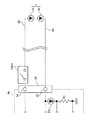
次に、本発明の第2の実施形態に係る発光ダイオード点灯装置について説明する。図3は、本発明の第2の実施形態に係る発光ダイオード点灯装置3aの構成の一例を示す回路図である。図3に示す発光ダイオード点灯装置3aと図2に示す発光ダイオード点灯装置3とでは、下記の点で異なる。すなわち、図3に示す発光ダイオード点灯装置3aでは、電流検出部37の代わりに電流検出用の発光ダイオードD6を備える。発光ダイオードD6は、表示用の発光ダイオードで、発光ダイオード素子41及び42よりも順方向電圧Vfが小さいものが用いられる。例えば、電流値Iopの電流を流した場合に、照明用の発光ダイオード素子41及び42の順方向電圧Vfが3.5V〜4.5V程度であるのに対し、発光ダイオードD6として順方向電圧Vfが1.5V〜2.5V程度となるようにされている。
次に、本発明の第3の実施形態に係る発光ダイオード点灯装置について説明する。図5は、本発明の第3の実施形態に係る発光ダイオード点灯装置3bの構成の一例を示す回路図である。図5に示す発光ダイオード点灯装置3bと図2に示す発光ダイオード点灯装置3とでは、下記の点で異なる。すなわち、図5に示す発光ダイオード点灯装置3bでは、電流検出部37の代わりにパルストランスT2(トランス)の一次巻線N3が、外部接続端子35と抵抗R1との間に介設されている。そして、パルストランスT2の二次巻線N4から出力されたパルス信号を平滑することにより端子台36から外部へ供給された電流レベルを表す検出電圧をコンパレータCP2へ出力するトランス電圧検知部の一例である電流検出部37aが備えられている。
2 筐体
3,3a,3b 発光ダイオード点灯装置
4 LED直列回路
5 セード部材
31,32 外部接続端子
33,36 端子台
34,35 外部接続端子
37,37a 電流検出部
38 PWM制御部
39,39a 直流電源部
41,42 発光ダイオード素子
43,44 配線
51 差動増幅回路
52 ラッチ回路
AMP1 差動アンプ
C1,C2,C3 コンデンサ
CP1,CP2 コンパレータ
D1,D2,D3,D4,D5,D7,D8,D9,D10 ダイオード
D6 発光ダイオード
DB1,DB2 ダイオードブリッジ
R1,R2,R3,R4 抵抗
T1 トランス
T2 パルストランス
Tr1,Tr2 トランジスタ
Claims (4)
- 外部に照明用の発光ダイオード素子が接続される外部接続部と、
前記外部接続部へ、前記発光ダイオード素子を発光させるための直流電圧を供給する直流電源部と、
前記直流電源部から前記外部接続部へ供給された出力電流の電流レベルを検出する電流検出部と、
前記直流電源部から前記照明用の発光ダイオード素子の逆耐圧に満たない電圧レベルである検出用電圧を出力させ、前記電流検出部により検出された前記出力電流の電流レベルが予め設定された基準レベルを超えた場合に、前記出力電流の電流レベルを前記照明用の発光ダイオード素子における発光用の一定の電流レベルにさせるべく前記直流電源部による直流電圧の出力レベルを変化させる制御部と、
を備えることを特徴とする発光ダイオード点灯装置。 - 前記電流検出部は、前記外部接続部を介して前記照明用の発光ダイオード素子と直列に接続される、前記照明用発光ダイオード素子よりも順方向電圧が小さい電流検出用の発光ダイオードと、
前記電流検出用の発光ダイオードにおける順方向電圧を、前記出力電流の電流レベルとして検出する順方向電圧検知部とを備えることを特徴とする請求項1記載の発光ダイオード点灯装置。 - 前記制御部は、前記直流電源部から前記検出用電圧をパルス状に出力させ、
前記電流検出部は、前記外部接続部を介して前記照明用の発光ダイオード素子と直列に一次巻線が接続されるトランスと、前記トランスにおける二次巻線の出力電圧を前記出力電流の電流レベルとして検出するトランス電圧検知部とを備えることを特徴とする請求項1記載の発光ダイオード点灯装置。 - 発光ダイオード点灯装置と、
前記発光ダイオード点灯装置を収容する筐体と、
を備え、
前記発光ダイオード点灯装置は、請求項1〜3のいずれかに記載の発光ダイオード点灯装置であることを特徴とする照明器具。
Priority Applications (1)
| Application Number | Priority Date | Filing Date | Title |
|---|---|---|---|
| JP2004333522A JP4529657B2 (ja) | 2004-11-17 | 2004-11-17 | 発光ダイオード点灯装置、及び照明器具 |
Applications Claiming Priority (1)
| Application Number | Priority Date | Filing Date | Title |
|---|---|---|---|
| JP2004333522A JP4529657B2 (ja) | 2004-11-17 | 2004-11-17 | 発光ダイオード点灯装置、及び照明器具 |
Publications (2)
| Publication Number | Publication Date |
|---|---|
| JP2006147252A JP2006147252A (ja) | 2006-06-08 |
| JP4529657B2 true JP4529657B2 (ja) | 2010-08-25 |
Family
ID=36626698
Family Applications (1)
| Application Number | Title | Priority Date | Filing Date |
|---|---|---|---|
| JP2004333522A Expired - Fee Related JP4529657B2 (ja) | 2004-11-17 | 2004-11-17 | 発光ダイオード点灯装置、及び照明器具 |
Country Status (1)
| Country | Link |
|---|---|
| JP (1) | JP4529657B2 (ja) |
Families Citing this family (11)
| Publication number | Priority date | Publication date | Assignee | Title |
|---|---|---|---|---|
| JP2006261147A (ja) * | 2005-03-15 | 2006-09-28 | Fuji Electric Device Technology Co Ltd | Led駆動装置および半導体集積回路 |
| JP4267647B2 (ja) * | 2006-08-10 | 2009-05-27 | 林化学工業株式会社 | 発光装置 |
| JP2009099627A (ja) * | 2007-10-12 | 2009-05-07 | Panasonic Electric Works Co Ltd | Led照明器具 |
| JP2009195033A (ja) * | 2008-02-14 | 2009-08-27 | Toshiba Lighting & Technology Corp | 電源装置及び照明器具 |
| JP2012084507A (ja) * | 2010-09-18 | 2012-04-26 | Toshiba Lighting & Technology Corp | 電流制限回路、ledモジュールおよびled照明装置 |
| JP5575607B2 (ja) * | 2010-10-28 | 2014-08-20 | 日置電機株式会社 | 順方向電圧測定装置および順方向電圧測定方法 |
| FR2968887B1 (fr) * | 2010-12-13 | 2012-12-21 | Schneider Electric Ind Sas | Dispositif et procede d'alimentation pour systeme d'eclairage a diodes electroluminescentes et ensemble d'eclairage comportant un tel dispositif |
| JP6036024B2 (ja) * | 2012-08-31 | 2016-11-30 | 東芝ライテック株式会社 | 照明装置 |
| TWI583258B (zh) * | 2015-01-30 | 2017-05-11 | 榮創能源科技股份有限公司 | 故障檢測設備及方法 |
| JP6553252B2 (ja) * | 2018-05-29 | 2019-07-31 | 和光電研株式会社 | 電源装置の保護装置 |
| JP7438774B2 (ja) * | 2020-02-05 | 2024-02-27 | アズビル株式会社 | 測定装置 |
Family Cites Families (3)
| Publication number | Priority date | Publication date | Assignee | Title |
|---|---|---|---|---|
| DE19930174A1 (de) * | 1999-06-30 | 2001-01-04 | Patent Treuhand Ges Fuer Elektrische Gluehlampen Mbh | Ansteuerschaltung für LED und zugehöriges Betriebsverfahren |
| JP4305802B2 (ja) * | 2001-02-14 | 2009-07-29 | 日立金属株式会社 | 発光ダイオード点灯回路 |
| JP4342262B2 (ja) * | 2003-10-03 | 2009-10-14 | アルエイド株式会社 | Led点灯制御装置、led点灯制御方法 |
-
2004
- 2004-11-17 JP JP2004333522A patent/JP4529657B2/ja not_active Expired - Fee Related
Also Published As
| Publication number | Publication date |
|---|---|
| JP2006147252A (ja) | 2006-06-08 |
Similar Documents
| Publication | Publication Date | Title |
|---|---|---|
| JP5426807B2 (ja) | 発光ダイオード用ドライバ | |
| JP4577525B2 (ja) | 照明装置 | |
| US20130127356A1 (en) | Led driving power supply apparatus and led lighting apparatus | |
| JP4975083B2 (ja) | 光源点灯装置および照明装置 | |
| US20110273112A1 (en) | Light emitting driver | |
| JP2004140367A (ja) | 電子機器の回路が保護可能な電源供給装置 | |
| JP2013020931A (ja) | Led点灯装置 | |
| JP4529657B2 (ja) | 発光ダイオード点灯装置、及び照明器具 | |
| JP4199201B2 (ja) | 電源装置及び照明装置 | |
| KR20110136537A (ko) | 과전압 보호와 정전류 구동을 위한 led 구동 회로 및 방법 | |
| JP2015173043A (ja) | Led点灯装置及びled照明装置 | |
| JP4741942B2 (ja) | Led点灯装置 | |
| JP2011034728A (ja) | 照明用光源装置 | |
| US8400072B2 (en) | Light emitting device driver circuit driving light emitting device by positive and negative voltages and method for driving light emitting device by positive and negative voltages | |
| JP2006222377A (ja) | 電源装置及び照明装置 | |
| JP2007157423A (ja) | 電源装置 | |
| JP6634940B2 (ja) | 調光点灯装置及び照明装置 | |
| JP6206814B2 (ja) | 点灯装置および該点灯装置を用いた照明システム | |
| JP6810904B2 (ja) | 電源装置および照明システム | |
| JP5197028B2 (ja) | 点灯装置及び表示装置及び誘導灯 | |
| KR101705831B1 (ko) | 발광 장치를 위한 조광 장치 | |
| KR101916162B1 (ko) | Led 병렬운전을 위한 전원 공급 장치 | |
| JP5157184B2 (ja) | 動作制御回路 | |
| JP6120217B2 (ja) | 可視光通信装置およびそれを用いた照明器具 | |
| JP2010136595A (ja) | 電流検出回路と電源回路 |
Legal Events
| Date | Code | Title | Description |
|---|---|---|---|
| A621 | Written request for application examination |
Free format text: JAPANESE INTERMEDIATE CODE: A621 Effective date: 20070925 |
|
| A977 | Report on retrieval |
Free format text: JAPANESE INTERMEDIATE CODE: A971007 Effective date: 20100421 |
|
| TRDD | Decision of grant or rejection written | ||
| A01 | Written decision to grant a patent or to grant a registration (utility model) |
Free format text: JAPANESE INTERMEDIATE CODE: A01 Effective date: 20100518 |
|
| A01 | Written decision to grant a patent or to grant a registration (utility model) |
Free format text: JAPANESE INTERMEDIATE CODE: A01 |
|
| A61 | First payment of annual fees (during grant procedure) |
Free format text: JAPANESE INTERMEDIATE CODE: A61 Effective date: 20100531 |
|
| R150 | Certificate of patent or registration of utility model |
Ref document number: 4529657 Country of ref document: JP Free format text: JAPANESE INTERMEDIATE CODE: R150 Free format text: JAPANESE INTERMEDIATE CODE: R150 |
|
| FPAY | Renewal fee payment (event date is renewal date of database) |
Free format text: PAYMENT UNTIL: 20130618 Year of fee payment: 3 |
|
| LAPS | Cancellation because of no payment of annual fees |