JP4558024B2 - Vacuum cleaner - Google Patents
Vacuum cleaner Download PDFInfo
- Publication number
- JP4558024B2 JP4558024B2 JP2007259688A JP2007259688A JP4558024B2 JP 4558024 B2 JP4558024 B2 JP 4558024B2 JP 2007259688 A JP2007259688 A JP 2007259688A JP 2007259688 A JP2007259688 A JP 2007259688A JP 4558024 B2 JP4558024 B2 JP 4558024B2
- Authority
- JP
- Japan
- Prior art keywords
- filter
- collecting container
- dust collecting
- dust
- opening
- Prior art date
- Legal status (The legal status is an assumption and is not a legal conclusion. Google has not performed a legal analysis and makes no representation as to the accuracy of the status listed.)
- Expired - Fee Related
Links
Images


Landscapes
- Filters For Electric Vacuum Cleaners (AREA)
Description
本発明は、集塵容器にフィルターを有する電気掃除機に関する。 The present invention relates to a vacuum cleaner having a filter in a dust collection container.
掃除機本体内に集塵容器、電動送風機収納部を有し、集塵容器内で塵埃と空気とに分離するタイプの電気掃除機、所謂、サイクロン方式の電気掃除機は、従来の塵埃を溜めるための紙パックが不必要であり、塵埃を溜めて捨てたいときに捨てることのできる簡便さから広く普及している。これらサイクロン方式の電気掃除機においては、集塵容器内で塵埃と空気を完全に分離することが困難であることから、集塵容器の排気口に塵埃を除去するためのフィルターが設けられている。(例えば、特許文献1参照)。 A vacuum cleaner of the type that has a dust collection container and an electric blower housing in the vacuum cleaner body and separates dust and air in the dust collection container, so-called cyclone type vacuum cleaner, collects conventional dust. The paper pack is not necessary and is widely used because it can be discarded when it is desired to collect and discard the dust. In these cyclone type vacuum cleaners, it is difficult to completely separate dust and air in the dust collecting container, and therefore a filter for removing dust is provided at the exhaust port of the dust collecting container. . (For example, refer to Patent Document 1).
しかしながら、集塵容器のフィルターは、集塵容器内で分離されない塵埃が付着するため目詰まりが起こり易く、フィルターの清掃等のメンテナンスを頻繁に行わなければないという欠点があった。
そこで、最近では、フィルターの上流側に使い捨てフィルター、例えばティッシュを装着させて、フィルターの目詰まりを抑制し、フィルターのメンテナンス頻度を少なくした商品が提案されている。そして、集塵容器に溜まった塵埃を集塵容器の開口部から簡単に排出できるように、集塵容器の開口部を開閉するフィルターを設け、クランプ機構を操作するとフィルターが回動して、集塵容器の開口部が開くようになっている。
しかしながら、提案されている商品のクランプ機構は、集塵容器が収納される収納室の挿入口の近傍に位置するため、使い捨てフィルターを集塵容器に装着した状態で収納室に収納すると、集塵容器からはみ出した使い捨てフィルターが、掃除機本体からもはみ出してしまい見栄えが悪くなるという欠点があった。
Therefore, recently, a product has been proposed in which a disposable filter, for example, a tissue is attached upstream of the filter to prevent clogging of the filter and reduce the frequency of filter maintenance. A filter that opens and closes the opening of the dust collection container is provided so that the dust collected in the dust collection container can be easily discharged from the opening of the dust collection container. The opening of the dust container is open.
However, since the proposed product clamping mechanism is located in the vicinity of the insertion port of the storage chamber in which the dust collection container is stored, when the disposable filter is mounted in the dust collection container, the dust collection is performed. The disposable filter that protrudes from the container protrudes from the main body of the vacuum cleaner and has a disadvantage that it looks bad.
本発明は上記欠点に鑑みなされたもので、使い捨てフィルターが掃除機本体からはみ出すことがない電気掃除機を提供することを課題とする。 This invention is made | formed in view of the said fault, and makes it a subject to provide the vacuum cleaner which a disposable filter does not protrude from a cleaner body.
上記課題を解決するための手段は、縦型の掃除機本体と、該掃除機本体の下方に設けられる床用吸込具と、前記掃除機本体の上方に延びるハンドルとを備え、前記掃除機本体には、下方に電動送風機を配設すると共に、該電動送風機の上方位置に前方が開口した挿入口を有する収納室を形成し、前記挿入口から収納室内に集塵容器を着脱自在に配設し、前記集塵容器は、下面を開口し、該下面の開口を、前記集塵容器の収容室の奥壁側に配置した取付部により回動自在に設けられたフィルター保持部にて閉塞し、前記フィルター保持部に、開口部を通過する空気から塵埃を濾過するフィルターを配設すると共に、前記集塵容器の開口部と前記フィルター保持部とによって使い捨てフィルターを挟持し、前記集塵容器の前面にカバーを一体的に形成し、該カバーを、前記集塵容器を収容室に収納した状態で掃除機本体の外面の一部を形成する形状に形成したことを特徴とする。 Means for solving the above-mentioned problems comprises a vertical cleaner body, a floor suction tool provided below the cleaner body, and a handle extending above the cleaner body, and the cleaner body. The electric blower is disposed below, and a storage chamber having an insertion opening opened at the front is formed at an upper position of the electric blower, and a dust collecting container is detachably disposed from the insertion opening into the storage chamber. The dust collecting container is opened at the lower surface, and the opening at the lower surface is closed by a filter holding portion that is rotatably provided by a mounting portion disposed on the back wall side of the storage chamber of the dust collecting container. The filter holding part is provided with a filter for filtering dust from the air passing through the opening, and a disposable filter is sandwiched between the opening of the dust collecting container and the filter holding part . Integrated cover on the front Form, the cover, characterized by being shaped to form part of the outer surface of the cleaner body while accommodating the dust collection container accommodating chamber.
前記集塵容器からはみ出した使い捨てフィルターの端部を上方に折り返した状態に保持する手段を設けることが好ましい。 It is preferable to provide means for holding the end portion of the disposable filter that protrudes from the dust collecting container in an upwardly folded state.
本発明の請求項1によれば、集塵容器内に溜まった塵埃を排出する場合は、フィルター保持部を回動させて、開口部より塵埃及び使い捨てフィルターを簡単に排出することができる等の効果を奏する。 According to the first aspect of the present invention, when discharging the dust accumulated in the dust collecting container, the filter holding part can be rotated so that the dust and the disposable filter can be easily discharged from the opening. There is an effect.
本発明の請求項2によれば、使い捨てフィルターの端部を上方に折り返した状態に保持する手段を形成したので、使い捨てフィルターが集塵容器の外面から大きくはみ出すのを防止することができる等の効果を奏する。
According to the second aspect of the present invention, since the means for holding the end of the disposable filter folded upward is formed, the disposable filter can be prevented from greatly protruding from the outer surface of the dust collecting container. There is an effect.
本発明の第1実施形態を図1乃至図5に基づいて以下に説明する。
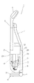
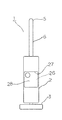
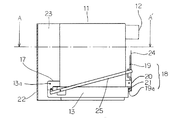
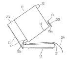
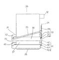
図1は、本願発明の第1実施形態が適用される縦型掃除機を側面からみた側面図、図2は、同縦型掃除機における集塵容器が収納されていないときの正面図、図3は、集塵容器の側面図、図4は、集塵容器内の塵埃と使い捨てフィルターを排出する状態を示す状態図、図5は、図4におけるA−A’断面図である。
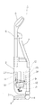
1は、本実施形態の縦型掃除機で、この縦型掃除機1は、縦長の掃除機本体2と、該掃除機本体2の下方に回動自在に設けられた床用吸込具3と、該床用吸込具3の前方と後方に各々設けられた車輪4と、前記掃除機本体2の上方に伸び上端側にグリップ部5が形成された筒状のハンドル6と、前記グリップ部5と前記ハンドル6との間から伸びる伸縮ホース7とを備えている。
前記ハンドル6は、前記伸縮ホース7と連通するとともに、前記掃除機本体2から着脱できる構成となっており、抜いた状態では、前記ハンドル6の先端開口部分から塵埃を吸引でき、挿入した状態では、先端開口部分はシール部材にて閉塞され、前記床用吸込具3から塵埃を吸引できるようになっている。
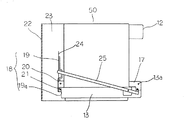
8は、前記掃除機本体2の下方に内蔵された電動送風機で、吸引口を上方に向けて配置(縦置)されている。9は、前記電動送風機8と連通する連通口で、この連通口9にフィルター10が配設されている。
11は、前記電動送風機8によって吸引された空気を旋回させて空気と塵埃とに分離し、且つ、分離された塵埃を集塵するサイクロン方式の集塵容器である。12は、前記集塵容器11の後面上方に形成された吸込口で、前記伸縮ホース7及び前記床用吸込具3と連通するようになっている。
13は、前記集塵容器11の下面の開口部14を開閉するフィルター保持部で、該フィルター保持部13には、メッシュフィルター15と、その後方(下流)にウレタンフィルター16とが配設されており、前記開口部14から排気される空気から前記集塵容器11内で分離できなかった小さい塵埃を除去するようになっている。
17は、前記集塵容器11の前方に位置し、後述する連結部23の両側に形成された取付部で、該取付部17の孔に前記フィルター保持部13の回転軸13aを挿入することにより、前記フィルター保持部13が前記集塵容器11に対し回動できるようになっている。18は、前記開口部14を前記フィルター保持部13で閉じた状態に保持するクランプ機構で、該クランプ機構18は、前記取付部17と対向する位置に設けられており、前記集塵容器11の後面側で前記開口部14近傍に設けられた操作レバー19と、該操作レバー19を支持する支持部20と、前記フィルター保持部13に形成され、前記操作レバー19の先端部19aと係合する突起21とから構成されている。
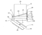
22は、前記集塵容器11と一体的に形成されたカバーで、前方に伸びる2つの連結部23からコの字状に形成され、前記取付部17及び前記フィルター保持部13を覆っている。よって、図3、図5に示すように、前記取付部17及び前記フィルター保持部13が見えないようになっている。
前記集塵容器11には、図3に示すように使い捨てフィルター24(本実施例では、市販されているティッシュ)が、前記開口部14と前記フィルター保持部13とによって挟持されて装着できるようになっている。また、使い捨てフィルター24の端部が前記集塵容器11の外面に大きくはみ出さないよう、略コの字状のフレーム25が前記フィルター保持部13に回動自在に取り付けられている。
26は、前記集塵容器11を収納する収納室で、前記電動送風機8の上方に設けられている。前記収納室26は、前方が開口した挿入口27を有し、前記集塵容器11を前記挿入口27から挿入させて収納できるようになっている。
ところで、前記集塵容器11に前記使い捨てフィルター24装着した状態で前記収納室26に収納した際、図1に示すように前記クランプ機構18が前記収納室26の前記挿入口27と対向する奥壁28側、即ち、前記挿入口27から離れた位置にあるので、前記集塵容器11からはみ出している使い捨てフィルター24が、前記掃除機本体2からはみ出すことがないように構成されている。また、前記カバー22が前記掃除機本体2の外面の一部を形成しているので、前記収納室26を覆うためのカバー等の別部品が不要である。更に、前記取付部17及び前記フィルター保持部13が前記カバー22によって見えないので、見栄えが良い。
A first embodiment of the present invention will be described below with reference to FIGS.
FIG. 1 is a side view of a vertical cleaner to which the first embodiment of the present invention is applied as viewed from the side, and FIG. 2 is a front view of the vertical cleaner when a dust collecting container is not accommodated. 3 is a side view of the dust collecting container, FIG. 4 is a state diagram showing a state in which the dust and the disposable filter in the dust collecting container are discharged, and FIG. 5 is a cross-sectional view taken along line AA ′ in FIG.
1 is a vertical cleaner according to the present embodiment. This
The
8 is an electric blower built in the lower part of the
13 is a filter holding part that opens and closes the
A
As shown in FIG. 3, a disposable filter 24 (in this embodiment, a commercially available tissue) is sandwiched between the
A
By the way, when the
以上のように構成された縦型掃除機1は、前記電動送風機8の駆動により前記床用吸込具3もしくは前記ハンドル6の先端開口部分から前記集塵容器11の前記吸込口12に空気が流入し、前記集塵容器11内で大きな塵埃と空気とに分離される。小さな塵埃は、前記開口部14を通過する際に使い捨てフィルター24及び前記メッシュフィルター15、前記ウレタンフィルター16、更に前記連通口9の前記フィルター10にて除去され、きれいになった空気は前記電動送風機8を冷却して前記掃除機本体2外へ排気される。
In the
使い捨てフィルター24を前記メッシュフィルター15及び前記ウレタンフィルター16の上流側に配設することにより前記メッシュフィルター15及び前記ウレタンフィルター16の目詰まりを抑制できるため、前記メッシュフィルター15及び前記ウレタンフィルター16のメンテナンスの手間を低減させることができる。また、使い捨てフィルター24は、前記開口部14と前記フィルター保持部13とによって挟持されて装着されることにより、使い捨てフィルター24の装着性を向上させることができる。
前記集塵容器11内に溜まった塵埃を排出する場合は、図4に示すように前記操作レバー19を操作すると、前記操作レバー19の前記先端部19aと前記突起21との係合が外れ、前記フィルター保持部13が回動し、前記開口部14より塵埃及び使い捨てフィルター24を簡単に排出することができる。
Since the clogging of the
When discharging the dust accumulated in the
排出が終了すると、新しい使い捨てフィルター24を前記メッシュフィルター15の上面に載置し、前記フィルター保持部13を回動した後、前記クランプ機構18にて前記フィルター保持部13を保持する。そして、前記集塵容器11を前記挿入口27から挿入して前記収納室26に装着する。このとき、前記クランプ機構18が前記収納室26の前記挿入口27と対向する奥壁28側、即ち、前記挿入口27から離れた位置にあるので、前記クランプ機構18からはみ出している使い捨てフィルター24が、前記掃除機本体2からはみ出すことがなくなり、見栄えが悪くなるという欠点を解消することができる。
また、前記集塵容器11の前記カバー22が前記掃除機本体2の外面の一部を形成するので、前記収納室26を覆うためのカバー等の別部品が不要であり、部品点数を少なくすることができる。
また、前記集塵容器11を前記収納室26に収納した状態では、前記取付部17及び前記フィルター保持部13が前記カバー22によって隠れてしまい、見栄えを向上させることができる。
尚、本実施形態では、クランプ機構18として、操作レバー19の先端部19sをフィルター保持部13の突起21に係合させる構成としたが、突起を設けることなく操作レバー19の先端部19aで、直接、フィルター保持部13を係合しても構わない。また、操作レバー19を集塵容器11に設けたがフィルター保持部13に設けても構わない。
また、本実施形態では、縦型掃除機タイプ(アップライト型掃除機)で説明したが、キャニスタータイプに適用しても、同様の効果を奏する。
次に、本発明の第2実施形態を図6及び図7に基づいて以下に説明する。尚、第1実施形態と同一部品については同一番号を付して説明を省略する。
When the discharge is completed, a new
Further, since the
Moreover, in the state which accommodated the said
In the present embodiment, the
Further, in the present embodiment, the vertical vacuum cleaner type (upright vacuum cleaner) has been described, but the same effect can be obtained even when applied to a canister type.
Next, a second embodiment of the present invention will be described below with reference to FIGS. The same parts as those in the first embodiment are denoted by the same reference numerals and description thereof is omitted.
第2実施形態の集塵容器11は、フィルター保持部13の形状に特徴があるもので、図6に示したフィルター保持部13は、前記クランプ機構18側に向かって漸次高くなるよう傾斜させた構成とし、逆に、図7に示したフィルター保持部13は、前記クランプ機構18側に向かって漸次低くなるよう傾斜させた構成としたものである。
図6のように前記クランプ機構18側に向かって漸次高くなるよう傾斜させた場合は、前記取付部17に対して前記クランプ機構18側が漸次高くなっているので、使い捨てフィルター24を前記フィルター保持部13の前記メッシュフィルター15上面にセットして前記フィルター保持部13を回動するとき、使い捨てフィルター24が前記メッシュフィルター15上面でずれにくくなり、使い捨てフィルター24を確実に装着できる。
The
As shown in FIG. 6, when it is inclined so as to gradually become higher toward the
図7のように前記クランプ機構18側に向かって漸次低くなるよう傾斜させた場合は、前記取付部17に対して前記クランプ機構18側が漸次低くなっているので、前記集塵容器11内の塵埃を前記開口部14から排出する際に前記フィルター保持部13を回動させた時、使い捨てフィルター24が前記フィルター保持部13に引っ掛かることなく塵埃を排出することできる。
次に、本発明の第3実施形態を図8乃至図10に基づいて以下に説明する。尚、第1実施形態及び第2実施形態と同一部品については同一番号を付して説明を省略する。
第3実施形態の集塵容器29は、フィルタ保持部が2つ設けられている。
30は、前記メッシュフィルター15が保持された第1フィルター保持部で、第1取付部31の孔に第1回転軸32を挿入して回動自在に装着されている。
33は、前記第1フィルター保持部30を前記開口部14に閉じた状態で保持する第1クランプ機構で、該第1クランプ機構33は、第1操作レバー34と、この第1レバー34を支持する第1支持部35と、前記第1操作レバー34の先端部34aが係合する第1突起6からなる。第1実施形態と同様、使い捨てフィルター24が前記開口部14と前記第1フィルター保持部30とで挟持されて、前記集塵容器29に装着できるようになっている。
37は、前記第1フィルター保持部30下側に形成された略四角状の連結部で、後述する第2フィルター保持部38が装着できるようになっている。
38は、前記ウレタンフィルター16が保持された第2フィルター保持部で、前記連結部37の前面で前記第1取付部31の下方の位置に設けられた第2取付部39の孔に第2回転軸40を挿入し、前記連結部37に対して回動自在に装着されている。
41は、前記第2フィルター保持部38を前記連結部37の開口部分に閉じた状態で保持する第2クランプ機構で、該第2クランプ機構41は、第2操作レバー42と、前記連結部37の後面に形成され、前記第2レバー42を支持する第2支持部43と、前記第2操作レバー42の先端部42aが係合する第2突起44とからなる。
上記構成により、前記集塵容器29内に溜まった塵埃を排出するときは、図9に示すように前記第1クランプ機構33を解除すると前記第1フィルター保持部30が回動し、使い捨てフィルター24とともに、前記開口部14から塵埃を排出することができる。
As shown in FIG. 7, when it is inclined so as to be gradually lowered toward the
Next, a third embodiment of the present invention will be described below with reference to FIGS. The same parts as those in the first embodiment and the second embodiment are denoted by the same reference numerals and description thereof is omitted.
The
Reference numeral 33 denotes a first clamp mechanism that holds the first
With the above configuration, when the dust accumulated in the
ところで、長期間使用を続けていると、使い捨てフィルター24を使用したとしても前記ウレタンフィルター16に塵埃が付着し目詰まりしてしまう。目詰まりすると空気流路が狭くなって吸込仕事率が低下することから、前記ウレタンフィルター16のメンテナンスが必要である。メンテナンス作業をする場合、第1実施形態の構成では、一つのフィルター保持部に前記メッシュフィルター15と前記ウレタンフィルター16を保持させているため、前記ウレタンフィルター16を取り出す場合、前記メッシュフィルター15を取り外さなければならず、非常に不便である。しかしながら、本実施形態では、前記メッシュフィルター15と前記ウレタンフィルター16とを各々のフィルター保持部に保持させているので、前記ウレタンフィルター16取り外す場合は、前記第2のクランプ機構41を解除するだけでよいので、前記ウレンタンフィルター16のメンテナンス作業を向上させることができる。
次に、本発明の第4実施形態を図11及び図12に基づいて以下に説明する。尚、第1実施形態乃至第3実施形態と同一部品については同一番号を付して説明を省略する。
第4実施形態の集塵容器50は、クランプ機構18の位置に特徴があるもので、図11に示すように前記クランプ機構18を前記挿入口27側に配置し、前記取付部17を前記収納室26の奥壁28側に配置している。即ち、第1実施形態の配置とは逆の構成である。第1実施形態の構成では、使い捨てフィルター24の一部を前記掃除機本体2からはみ出さないようにすることができるが、前記クランプ機構18が前記連通口9の上方にあるため、使い捨てフィルター24の装着状態によっては、前記クランプ機構18から垂れ下がる使い捨てフィルター14で前記連通口9を塞ぐことも考えられる。従って、前記クランプ機構18を前記挿入口27側に配置することにより、前記クランプ機構18が前記連通口9から離れた位置となるため、前記クランプ機構18から垂れ下がる使い捨てフィルター24で前記連通口9を塞ぐことを防止できる。
By the way, if it is used for a long time, even if the
Next, a fourth embodiment of the present invention will be described below with reference to FIGS. The same parts as those in the first to third embodiments are denoted by the same reference numerals and description thereof is omitted.
The
14 開口部
11 集塵容器
27 挿入口
26 収納室
8 電動送風機
16 ウレタンフィルター
13 フィルター保持部
24 使い捨てフィルター
18 クランプ機構
28 奥壁
17 取付部
22 カバー
14 opening
11 Dust collection container
27 insertion slot
26 Storage room
8 Electric blower
16 Urethane filter
13 Filter holder
24 Disposable filter
18 Clamp mechanism
28 Back Wall
17 Mounting part
22 Cover
Claims (2)
前記掃除機本体には、下方に電動送風機を配設すると共に、該電動送風機の上方位置に前方が開口した挿入口を有する収納室を形成し、前記挿入口から収納室内に集塵容器を着脱自在に配設し、
前記集塵容器は、下面を開口し、該下面の開口を、前記集塵容器の収容室の奥壁側に配置した取付部により回動自在に設けられたフィルター保持部にて閉塞し、前記フィルター保持部に、開口部を通過する空気から塵埃を濾過するフィルターを配設すると共に、前記集塵容器の開口部と前記フィルター保持部とによって使い捨てフィルターを挟持し、
前記集塵容器の前面にカバーを一体的に形成し、該カバーを、前記集塵容器を収容室に収納した状態で掃除機本体の外面の一部を形成する形状に形成したことを特徴とする電気掃除機。 A vertical vacuum cleaner main body, a floor suction tool provided below the vacuum cleaner main body, and a handle extending above the vacuum cleaner main body,
The vacuum cleaner body is provided with an electric blower below, and a storage chamber having an insertion opening opened at the front is formed at an upper position of the electric blower, and a dust collecting container is attached to and removed from the insertion opening into the storage chamber. Arrange freely,
The dust collecting container has an opening on a lower surface, and the opening on the lower surface is closed by a filter holding portion that is rotatably provided by a mounting portion disposed on the inner wall side of the storage chamber of the dust collecting container, In the filter holding part, a filter for filtering dust from the air passing through the opening is disposed, and a disposable filter is sandwiched between the opening of the dust collecting container and the filter holding part ,
A cover is integrally formed on the front surface of the dust collecting container, and the cover is formed in a shape that forms a part of the outer surface of the cleaner body in a state in which the dust collecting container is stored in a storage chamber. Electric vacuum cleaner.
Priority Applications (1)
| Application Number | Priority Date | Filing Date | Title |
|---|---|---|---|
| JP2007259688A JP4558024B2 (en) | 2007-10-03 | 2007-10-03 | Vacuum cleaner |
Applications Claiming Priority (1)
| Application Number | Priority Date | Filing Date | Title |
|---|---|---|---|
| JP2007259688A JP4558024B2 (en) | 2007-10-03 | 2007-10-03 | Vacuum cleaner |
Related Parent Applications (1)
| Application Number | Title | Priority Date | Filing Date |
|---|---|---|---|
| JP2005215420A Division JP2007029332A (en) | 2005-07-26 | 2005-07-26 | Electric cleaner |
Publications (2)
| Publication Number | Publication Date |
|---|---|
| JP2008068100A JP2008068100A (en) | 2008-03-27 |
| JP4558024B2 true JP4558024B2 (en) | 2010-10-06 |
Family
ID=39290184
Family Applications (1)
| Application Number | Title | Priority Date | Filing Date |
|---|---|---|---|
| JP2007259688A Expired - Fee Related JP4558024B2 (en) | 2007-10-03 | 2007-10-03 | Vacuum cleaner |
Country Status (1)
| Country | Link |
|---|---|
| JP (1) | JP4558024B2 (en) |
Family Cites Families (8)
| Publication number | Priority date | Publication date | Assignee | Title |
|---|---|---|---|---|
| JPS5321762U (en) * | 1976-07-30 | 1978-02-23 | ||
| JPS5674642U (en) * | 1979-11-12 | 1981-06-18 | ||
| JPS59108528A (en) * | 1983-11-25 | 1984-06-23 | 松下電器産業株式会社 | Upright vacuum cleaner |
| JPS61137355U (en) * | 1985-02-19 | 1986-08-26 | ||
| JPH0747009B2 (en) * | 1985-08-08 | 1995-05-24 | 三洋電機株式会社 | Small portable vacuum cleaner |
| JP3530436B2 (en) * | 1999-01-29 | 2004-05-24 | 三洋電機株式会社 | Vacuum cleaner dust collector and upright type vacuum cleaner |
| JP2005168623A (en) * | 2003-12-09 | 2005-06-30 | Matsushita Electric Ind Co Ltd | Electric vacuum cleaner |
| JP2005204880A (en) * | 2004-01-22 | 2005-08-04 | Sanyo Electric Co Ltd | Vacuum cleaner and its dust collector |
-
2007
- 2007-10-03 JP JP2007259688A patent/JP4558024B2/en not_active Expired - Fee Related
Also Published As
| Publication number | Publication date |
|---|---|
| JP2008068100A (en) | 2008-03-27 |
Similar Documents
| Publication | Publication Date | Title |
|---|---|---|
| US7682414B2 (en) | Dust collecting unit for use in cleaner | |
| US20040163368A1 (en) | Dust collecting container for vacuum cleaner | |
| JP4753990B2 (en) | Vacuum cleaner | |
| JP3983047B2 (en) | Electric vacuum cleaner | |
| JP4262731B2 (en) | Electric vacuum cleaner | |
| JP2001314354A (en) | Electric vacuum cleaner | |
| JP4558024B2 (en) | Vacuum cleaner | |
| JP2007029332A (en) | Electric cleaner | |
| JP2012000210A (en) | Vacuum cleaner | |
| JP2009504235A (en) | Vacuum cleaner filter mounting structure | |
| JP2007216046A (en) | Vacuum cleaner | |
| JP4557840B2 (en) | Vacuum cleaner | |
| JP4567621B2 (en) | Vacuum cleaner | |
| JP2007244844A (en) | Electric vacuum cleaner | |
| JP2008011985A (en) | Dust collecting container and vacuum cleaner | |
| JP2008125607A (en) | Electric vacuum cleaner | |
| JP2007054266A (en) | Vacuum cleaner | |
| JP2006061540A (en) | Electric vacuum cleaner | |
| JP4324599B2 (en) | Electric vacuum cleaner | |
| JP5567394B2 (en) | Dust collector and vacuum cleaner | |
| KR20100138837A (en) | Dust collector and electric cleaner | |
| JP2006346281A (en) | Vacuum cleaner and dust collector | |
| JP2006043203A (en) | Electric vacuum cleaner | |
| JP5809038B2 (en) | Electric vacuum cleaner | |
| JP5258421B2 (en) | Electric vacuum cleaner |
Legal Events
| Date | Code | Title | Description |
|---|---|---|---|
| A621 | Written request for application examination |
Free format text: JAPANESE INTERMEDIATE CODE: A621 Effective date: 20080212 |
|
| A977 | Report on retrieval |
Free format text: JAPANESE INTERMEDIATE CODE: A971007 Effective date: 20091023 |
|
| A131 | Notification of reasons for refusal |
Free format text: JAPANESE INTERMEDIATE CODE: A131 Effective date: 20091201 |
|
| A521 | Request for written amendment filed |
Free format text: JAPANESE INTERMEDIATE CODE: A523 Effective date: 20100125 |
|
| A131 | Notification of reasons for refusal |
Free format text: JAPANESE INTERMEDIATE CODE: A131 Effective date: 20100420 |
|
| A521 | Request for written amendment filed |
Free format text: JAPANESE INTERMEDIATE CODE: A523 Effective date: 20100603 |
|
| TRDD | Decision of grant or rejection written | ||
| A01 | Written decision to grant a patent or to grant a registration (utility model) |
Free format text: JAPANESE INTERMEDIATE CODE: A01 Effective date: 20100622 |
|
| A01 | Written decision to grant a patent or to grant a registration (utility model) |
Free format text: JAPANESE INTERMEDIATE CODE: A01 |
|
| A61 | First payment of annual fees (during grant procedure) |
Free format text: JAPANESE INTERMEDIATE CODE: A61 Effective date: 20100720 |
|
| FPAY | Renewal fee payment (event date is renewal date of database) |
Free format text: PAYMENT UNTIL: 20130730 Year of fee payment: 3 |
|
| LAPS | Cancellation because of no payment of annual fees |