JP4580720B2 - リモートセンシング装置 - Google Patents
リモートセンシング装置 Download PDFInfo
- Publication number
- JP4580720B2 JP4580720B2 JP2004262702A JP2004262702A JP4580720B2 JP 4580720 B2 JP4580720 B2 JP 4580720B2 JP 2004262702 A JP2004262702 A JP 2004262702A JP 2004262702 A JP2004262702 A JP 2004262702A JP 4580720 B2 JP4580720 B2 JP 4580720B2
- Authority
- JP
- Japan
- Prior art keywords
- frequency
- rotation
- carrier frequency
- rotating plate
- optical pattern
- Prior art date
- Legal status (The legal status is an assumption and is not a legal conclusion. Google has not performed a legal analysis and makes no representation as to the accuracy of the status listed.)
- Expired - Fee Related
Links
Images



Classifications
-
- G—PHYSICS
- G01—MEASURING; TESTING
- G01P—MEASURING LINEAR OR ANGULAR SPEED, ACCELERATION, DECELERATION, OR SHOCK; INDICATING PRESENCE, ABSENCE, OR DIRECTION, OF MOVEMENT
- G01P3/00—Measuring linear or angular speed; Measuring differences of linear or angular speeds
- G01P3/42—Devices characterised by the use of electric or magnetic means
- G01P3/44—Devices characterised by the use of electric or magnetic means for measuring angular speed
- G01P3/48—Devices characterised by the use of electric or magnetic means for measuring angular speed by measuring frequency of generated current or voltage
- G01P3/481—Devices characterised by the use of electric or magnetic means for measuring angular speed by measuring frequency of generated current or voltage of pulse signals
- G01P3/486—Devices characterised by the use of electric or magnetic means for measuring angular speed by measuring frequency of generated current or voltage of pulse signals delivered by photo-electric detectors
-
- G—PHYSICS
- G01—MEASURING; TESTING
- G01D—MEASURING NOT SPECIALLY ADAPTED FOR A SPECIFIC VARIABLE; ARRANGEMENTS FOR MEASURING TWO OR MORE VARIABLES NOT COVERED IN A SINGLE OTHER SUBCLASS; TARIFF METERING APPARATUS; MEASURING OR TESTING NOT OTHERWISE PROVIDED FOR
- G01D5/00—Mechanical means for transferring the output of a sensing member; Means for converting the output of a sensing member to another variable where the form or nature of the sensing member does not constrain the means for converting; Transducers not specially adapted for a specific variable
- G01D5/26—Mechanical means for transferring the output of a sensing member; Means for converting the output of a sensing member to another variable where the form or nature of the sensing member does not constrain the means for converting; Transducers not specially adapted for a specific variable characterised by optical transfer means, i.e. using infrared, visible, or ultraviolet light
- G01D5/28—Mechanical means for transferring the output of a sensing member; Means for converting the output of a sensing member to another variable where the form or nature of the sensing member does not constrain the means for converting; Transducers not specially adapted for a specific variable characterised by optical transfer means, i.e. using infrared, visible, or ultraviolet light with deflection of beams of light, e.g. for direct optical indication
- G01D5/30—Mechanical means for transferring the output of a sensing member; Means for converting the output of a sensing member to another variable where the form or nature of the sensing member does not constrain the means for converting; Transducers not specially adapted for a specific variable characterised by optical transfer means, i.e. using infrared, visible, or ultraviolet light with deflection of beams of light, e.g. for direct optical indication the beams of light being detected by photocells
-
- G—PHYSICS
- G01—MEASURING; TESTING
- G01D—MEASURING NOT SPECIALLY ADAPTED FOR A SPECIFIC VARIABLE; ARRANGEMENTS FOR MEASURING TWO OR MORE VARIABLES NOT COVERED IN A SINGLE OTHER SUBCLASS; TARIFF METERING APPARATUS; MEASURING OR TESTING NOT OTHERWISE PROVIDED FOR
- G01D5/00—Mechanical means for transferring the output of a sensing member; Means for converting the output of a sensing member to another variable where the form or nature of the sensing member does not constrain the means for converting; Transducers not specially adapted for a specific variable
- G01D5/26—Mechanical means for transferring the output of a sensing member; Means for converting the output of a sensing member to another variable where the form or nature of the sensing member does not constrain the means for converting; Transducers not specially adapted for a specific variable characterised by optical transfer means, i.e. using infrared, visible, or ultraviolet light
- G01D5/32—Mechanical means for transferring the output of a sensing member; Means for converting the output of a sensing member to another variable where the form or nature of the sensing member does not constrain the means for converting; Transducers not specially adapted for a specific variable characterised by optical transfer means, i.e. using infrared, visible, or ultraviolet light with attenuation or whole or partial obturation of beams of light
- G01D5/34—Mechanical means for transferring the output of a sensing member; Means for converting the output of a sensing member to another variable where the form or nature of the sensing member does not constrain the means for converting; Transducers not specially adapted for a specific variable characterised by optical transfer means, i.e. using infrared, visible, or ultraviolet light with attenuation or whole or partial obturation of beams of light the beams of light being detected by photocells
- G01D5/347—Mechanical means for transferring the output of a sensing member; Means for converting the output of a sensing member to another variable where the form or nature of the sensing member does not constrain the means for converting; Transducers not specially adapted for a specific variable characterised by optical transfer means, i.e. using infrared, visible, or ultraviolet light with attenuation or whole or partial obturation of beams of light the beams of light being detected by photocells using displacement encoding scales
- G01D5/3473—Circular or rotary encoders
-
- G—PHYSICS
- G01—MEASURING; TESTING
- G01P—MEASURING LINEAR OR ANGULAR SPEED, ACCELERATION, DECELERATION, OR SHOCK; INDICATING PRESENCE, ABSENCE, OR DIRECTION, OF MOVEMENT
- G01P3/00—Measuring linear or angular speed; Measuring differences of linear or angular speeds
- G01P3/36—Devices characterised by the use of optical means, e.g. using infrared, visible, or ultraviolet light
-
- G—PHYSICS
- G01—MEASURING; TESTING
- G01P—MEASURING LINEAR OR ANGULAR SPEED, ACCELERATION, DECELERATION, OR SHOCK; INDICATING PRESENCE, ABSENCE, OR DIRECTION, OF MOVEMENT
- G01P3/00—Measuring linear or angular speed; Measuring differences of linear or angular speeds
- G01P3/42—Devices characterised by the use of electric or magnetic means
- G01P3/44—Devices characterised by the use of electric or magnetic means for measuring angular speed
-
- G—PHYSICS
- G01—MEASURING; TESTING
- G01S—RADIO DIRECTION-FINDING; RADIO NAVIGATION; DETERMINING DISTANCE OR VELOCITY BY USE OF RADIO WAVES; LOCATING OR PRESENCE-DETECTING BY USE OF THE REFLECTION OR RERADIATION OF RADIO WAVES; ANALOGOUS ARRANGEMENTS USING OTHER WAVES
- G01S17/00—Systems using the reflection or reradiation of electromagnetic waves other than radio waves, e.g. lidar systems
- G01S17/02—Systems using the reflection of electromagnetic waves other than radio waves
- G01S17/50—Systems of measurement based on relative movement of target
Landscapes
- Physics & Mathematics (AREA)
- General Physics & Mathematics (AREA)
- Engineering & Computer Science (AREA)
- Electromagnetism (AREA)
- Power Engineering (AREA)
- Computer Networks & Wireless Communication (AREA)
- Radar, Positioning & Navigation (AREA)
- Remote Sensing (AREA)
- Optical Radar Systems And Details Thereof (AREA)
- Optical Transform (AREA)
Description
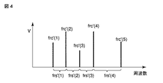
nd = frc / frs’
以上より、回転周波数frsは、キャリア周波数frcと分割数nより次式で求めることができる。
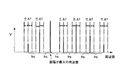
したがって、上記構成によるリモートセンシング装置は、FM変調の変調指数が大きい場合には、キャリア周波数の候補値が2つの山のような分布となり、正しいキャリ周波数を求めることができないことを考慮し、キャリア周波数を求めた後、回転周波数を求めるのではなく、側波周波数候補値を選定し、それらの間隔の多数決で回転周波数概略値を求め、その後、キャリア周波数候補値を求め、回転周波数候補値を基に回転周波数を選定して、得られたキャリア周波数、回転周波数の結果を演算し表示するようにしているので、キャリア周波数が最大値とならない場合でも、正しくキャリア周波数候補値を選定することが可能となる。
Claims (2)
- 回転中心から放射状に透過/不透過の対による分割領域を交互に配置したパターン形成面を備え、任意の回転周波数で回転する光学パターン回転板を測定対象とし、当該測定対象の回転周波数を求めるリモートセンシング装置において、
前記光学パターン回転板の前記パターン形成面に向けてレーザ光源で発生されるレーザ光を送出し、前記パターン形成面の透過/不透過の領域によって変調を受けた前記レーザ光の反射光を光受信器によって受信する光学系装置と、
前記光受信器によって得られた前記反射光の受信信号を周波数領域の信号に変換する周波数変換器と、
前記周波数変換器によって得られた周波数領域の信号の周波数成分を分析する周波数分析器とを具備し、
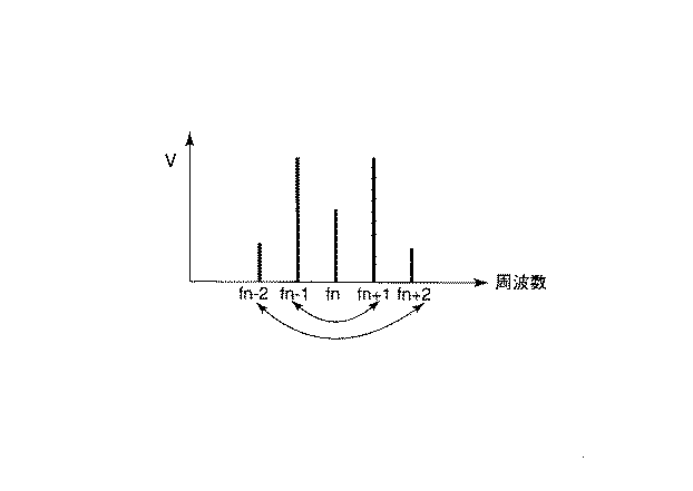
前記周波数分析器は、前記周波数領域の信号の周波数成分の分析結果から側波周波数の候補値を選定し、それらの間隔の多数決で前記光学パターン回転板の回転周波数の概略値を求め、この概略値から前記光学パターン回転板からの反射光のキャリア周波数の候補値を求め、その候補値の左右対称度からキャリア周波数を求め、求めたキャリア周波数と前記回転周波数の概略値から前記分割領域による分割数を求め、求めた分割数と前記キャリア周波数から前記光学パターン回転板の回転周波数を選定することを特徴とするリモートセンシング装置。 - 回転中心から放射状に透過/不透過の対による分割領域を交互に配置したパターン形成面を備え、任意の回転周波数で回転する光学パターン回転板を測定対象とし、当該測定対象の回転周波数を求めるリモートセンシング装置に用いられ、レーザ光を前記測定対象とする光学パターン回転板のパターン形成面に向けて送出し、前記パターン形成面の透過/不透過の領域によって変調を受けた前記レーザ光の反射光を光受信器によって受信したことによって得られる信号を周波数領域に変換して周波数分析を行う周波数分析方法において、
前記周波数領域に変換された信号の周波数成分の分析結果から側波周波数の候補値を選定し、
前記側波周波数の候補値の間隔の多数決で前記光学パターン回転板の回転周波数の概略値を求め、
この概略値から前記光学パターン回転板からの反射光のキャリア周波数の候補値を求め、
前記キャリア周波数の候補値の左右対称度からキャリア周波数を求め、
求めたキャリア周波数と前記回転周波数の概略値から前記分割領域による分割数を求め、求めた分割数と前記キャリア周波数から前記光学パターン回転板の回転周波数を選定することを特徴とするリモートセンシング装置の周波数分析方法。
Priority Applications (4)
| Application Number | Priority Date | Filing Date | Title |
|---|---|---|---|
| JP2004262702A JP4580720B2 (ja) | 2004-09-09 | 2004-09-09 | リモートセンシング装置 |
| EP05782002.9A EP1681572B1 (en) | 2004-09-09 | 2005-09-09 | Remote sensing of rotational frequency |
| PCT/JP2005/016650 WO2006028219A1 (ja) | 2004-09-09 | 2005-09-09 | リモートセンシング装置 |
| US11/365,860 US7161733B2 (en) | 2004-09-09 | 2006-03-02 | Remote sensing apparatus and a frequency analysis method of the remote sensing apparatus |
Applications Claiming Priority (1)
| Application Number | Priority Date | Filing Date | Title |
|---|---|---|---|
| JP2004262702A JP4580720B2 (ja) | 2004-09-09 | 2004-09-09 | リモートセンシング装置 |
Publications (3)
| Publication Number | Publication Date |
|---|---|
| JP2006078343A JP2006078343A (ja) | 2006-03-23 |
| JP2006078343A5 JP2006078343A5 (ja) | 2007-02-08 |
| JP4580720B2 true JP4580720B2 (ja) | 2010-11-17 |
Family
ID=36036501
Family Applications (1)
| Application Number | Title | Priority Date | Filing Date |
|---|---|---|---|
| JP2004262702A Expired - Fee Related JP4580720B2 (ja) | 2004-09-09 | 2004-09-09 | リモートセンシング装置 |
Country Status (4)
| Country | Link |
|---|---|
| US (1) | US7161733B2 (ja) |
| EP (1) | EP1681572B1 (ja) |
| JP (1) | JP4580720B2 (ja) |
| WO (1) | WO2006028219A1 (ja) |
Families Citing this family (16)
| Publication number | Priority date | Publication date | Assignee | Title |
|---|---|---|---|---|
| WO2005116678A2 (en) * | 2004-05-26 | 2005-12-08 | Interactive Sports Games A/S | A method of and an apparatus for determining information relating to a projectile, such as a golf ball |
| EP3098624A1 (en) | 2004-07-02 | 2016-11-30 | Trackman A/S | A method and apparatus for determining a deviation between an actual direction of a launched projectile and a predetermined direction |
| ATE471746T1 (de) * | 2005-03-03 | 2010-07-15 | Interactive Sports Games As | Bestimmung von drallparametern eines sportballes |
| US9645235B2 (en) | 2005-03-03 | 2017-05-09 | Trackman A/S | Determination of spin parameters of a sports ball |
| US10393870B2 (en) | 2005-03-03 | 2019-08-27 | Trackman A/S | Determination of spin parameters of a sports ball |
| KR101845503B1 (ko) | 2009-01-29 | 2018-04-04 | 트랙맨 에이/에스 | 레이더 및 촬상 요소를 포함하는 조립체 |
| CN101718866B (zh) * | 2009-11-24 | 2012-09-05 | 中国科学院对地观测与数字地球科学中心 | 一种改进的遥感影像地形校正物理方法 |
| CN102087313B (zh) * | 2010-11-22 | 2013-06-19 | 航天恒星科技有限公司 | 一种卫星搜救信号的频率估计方法 |
| EP2605036B1 (en) | 2011-12-16 | 2019-10-23 | Trackman A/S | A method and a sensor for determining a direction-of-arrival of impingent radiation |
| CN102568034B (zh) * | 2011-12-30 | 2014-01-15 | 中国科学院长春光学精密机械与物理研究所 | 空间光学遥感器对实际地物成像的计算机仿真系统 |
| WO2014110398A1 (en) * | 2013-01-10 | 2014-07-17 | Edh Us Llc | Ball spin rate measurement |
| CN103198314B (zh) * | 2013-02-20 | 2015-11-25 | 北京农业信息技术研究中心 | 遥感图像辐射校正方法 |
| CN104700356B (zh) * | 2015-04-07 | 2017-09-01 | 北京师范大学 | 一种遥感图像反立体校正方法 |
| US10379214B2 (en) | 2016-07-11 | 2019-08-13 | Trackman A/S | Device, system and method for tracking multiple projectiles |
| US10444339B2 (en) | 2016-10-31 | 2019-10-15 | Trackman A/S | Skid and roll tracking system |
| US10989791B2 (en) | 2016-12-05 | 2021-04-27 | Trackman A/S | Device, system, and method for tracking an object using radar data and imager data |
Family Cites Families (5)
| Publication number | Priority date | Publication date | Assignee | Title |
|---|---|---|---|---|
| US3681690A (en) * | 1970-11-10 | 1972-08-01 | Us Army | Optical angular accelerometer |
| US5294075A (en) * | 1991-08-28 | 1994-03-15 | The Boeing Company | High accuracy optical position sensing system |
| DE4133269A1 (de) * | 1991-10-08 | 1993-04-15 | Bosch Gmbh Robert | Verfahren zur messung der drehzahl eines rotierenden teiles |
| DE4331024A1 (de) * | 1993-09-13 | 1995-03-16 | Pce Process Control Electronic | FFT-gestütztes Verfahren zur Bestimmung der stationären Drehzahl und Unwuchten von An- und Abtriebswellen aller Art |
| JP3846725B2 (ja) * | 2003-07-18 | 2006-11-15 | 防衛庁技術研究本部長 | リモートセンシング装置及びリモートセンシング装置の周波数分析方法 |
-
2004
- 2004-09-09 JP JP2004262702A patent/JP4580720B2/ja not_active Expired - Fee Related
-
2005
- 2005-09-09 WO PCT/JP2005/016650 patent/WO2006028219A1/ja not_active Ceased
- 2005-09-09 EP EP05782002.9A patent/EP1681572B1/en not_active Expired - Lifetime
-
2006
- 2006-03-02 US US11/365,860 patent/US7161733B2/en not_active Expired - Lifetime
Also Published As
| Publication number | Publication date |
|---|---|
| WO2006028219A1 (ja) | 2006-03-16 |
| EP1681572B1 (en) | 2014-02-12 |
| EP1681572A1 (en) | 2006-07-19 |
| US7161733B2 (en) | 2007-01-09 |
| EP1681572A4 (en) | 2010-06-02 |
| US20060169932A1 (en) | 2006-08-03 |
| JP2006078343A (ja) | 2006-03-23 |
Similar Documents
| Publication | Publication Date | Title |
|---|---|---|
| JP4580720B2 (ja) | リモートセンシング装置 | |
| WO2017187510A1 (ja) | 距離計測装置、距離計測方法、及び形状計測装置 | |
| JP6814180B2 (ja) | 分布光ファイバ振動計測装置および分布光ファイバ振動計測方法 | |
| JP2019523393A5 (ja) | ||
| JP5344492B2 (ja) | 構造物欠陥の映像化方法、構造物欠陥の映像化装置、気泡の映像化方法および気泡や病変部の映像化装置 | |
| JP2009162678A (ja) | レーザレーダ装置 | |
| US10458953B2 (en) | Method and system for acquiring natural frequency of diaphragm | |
| JP6205685B2 (ja) | アクティブソーナー装置、アクティブソーナー信号処理方法、及び、その信号処理プログラム | |
| US20180259455A1 (en) | Methods and Apparatus for Fluorescence Lifetime Imaging with Pulsed Light | |
| KR20200004233A (ko) | 직교 코드를 이용하는 분광 장치 및 분광 방법 | |
| KR101543146B1 (ko) | 진동 장치의 상태 판단 방법 | |
| JP2006078343A5 (ja) | ||
| US8848176B2 (en) | Dispersion measurement apparatus using a wavelet transform to determine a time difference based on indentified peaks | |
| US5692072A (en) | Edge detecting device | |
| JP2010078364A (ja) | レーダ装置 | |
| JP2007170941A (ja) | 歪み測定装置、方法、プログラムおよび記録媒体 | |
| CN113767267B (zh) | 分析装置 | |
| JP3846725B2 (ja) | リモートセンシング装置及びリモートセンシング装置の周波数分析方法 | |
| JP4769668B2 (ja) | 光リフレクトメトリ測定方法および装置 | |
| JP2008014696A (ja) | ムラ検査装置、画像表示装置、ムラ検査方法および画像表示方法 | |
| JP6171502B2 (ja) | プロジェクタおよびプロジェクタ機能を有する電子機器 | |
| US20250369824A1 (en) | Measurement system | |
| CN120693491B (zh) | 测定系统 | |
| US20250094665A1 (en) | Information processing device, information processing method, and computer program product | |
| US20240280404A1 (en) | Monitoring system, method of monitoring and storage medium |
Legal Events
| Date | Code | Title | Description |
|---|---|---|---|
| A521 | Request for written amendment filed |
Free format text: JAPANESE INTERMEDIATE CODE: A523 Effective date: 20061207 |
|
| A621 | Written request for application examination |
Free format text: JAPANESE INTERMEDIATE CODE: A621 Effective date: 20061207 |
|
| A131 | Notification of reasons for refusal |
Free format text: JAPANESE INTERMEDIATE CODE: A131 Effective date: 20100330 |
|
| A521 | Request for written amendment filed |
Free format text: JAPANESE INTERMEDIATE CODE: A523 Effective date: 20100531 |
|
| TRDD | Decision of grant or rejection written | ||
| A01 | Written decision to grant a patent or to grant a registration (utility model) |
Free format text: JAPANESE INTERMEDIATE CODE: A01 Effective date: 20100803 |
|
| A01 | Written decision to grant a patent or to grant a registration (utility model) |
Free format text: JAPANESE INTERMEDIATE CODE: A01 |
|
| A61 | First payment of annual fees (during grant procedure) |
Free format text: JAPANESE INTERMEDIATE CODE: A61 Effective date: 20100830 |
|
| FPAY | Renewal fee payment (event date is renewal date of database) |
Free format text: PAYMENT UNTIL: 20130903 Year of fee payment: 3 |
|
| R151 | Written notification of patent or utility model registration |
Ref document number: 4580720 Country of ref document: JP Free format text: JAPANESE INTERMEDIATE CODE: R151 |
|
| FPAY | Renewal fee payment (event date is renewal date of database) |
Free format text: PAYMENT UNTIL: 20130903 Year of fee payment: 3 |
|
| LAPS | Cancellation because of no payment of annual fees |