JP4584880B2 - インバータ回路 - Google Patents
インバータ回路 Download PDFInfo
- Publication number
- JP4584880B2 JP4584880B2 JP2006205260A JP2006205260A JP4584880B2 JP 4584880 B2 JP4584880 B2 JP 4584880B2 JP 2006205260 A JP2006205260 A JP 2006205260A JP 2006205260 A JP2006205260 A JP 2006205260A JP 4584880 B2 JP4584880 B2 JP 4584880B2
- Authority
- JP
- Japan
- Prior art keywords
- circuit
- voltage
- series
- transformer
- balancer
- Prior art date
- Legal status (The legal status is an assumption and is not a legal conclusion. Google has not performed a legal analysis and makes no representation as to the accuracy of the status listed.)
- Expired - Fee Related
Links
Images

Classifications
-
- H—ELECTRICITY
- H05—ELECTRIC TECHNIQUES NOT OTHERWISE PROVIDED FOR
- H05B—ELECTRIC HEATING; ELECTRIC LIGHT SOURCES NOT OTHERWISE PROVIDED FOR; CIRCUIT ARRANGEMENTS FOR ELECTRIC LIGHT SOURCES, IN GENERAL
- H05B41/00—Circuit arrangements or apparatus for igniting or operating discharge lamps
- H05B41/14—Circuit arrangements
- H05B41/26—Circuit arrangements in which the lamp is fed by power derived from DC by means of a converter, e.g. by high-voltage DC
- H05B41/28—Circuit arrangements in which the lamp is fed by power derived from DC by means of a converter, e.g. by high-voltage DC using static converters
- H05B41/282—Circuit arrangements in which the lamp is fed by power derived from DC by means of a converter, e.g. by high-voltage DC using static converters with semiconductor devices
- H05B41/285—Arrangements for protecting lamps or circuits against abnormal operating conditions
- H05B41/2851—Arrangements for protecting lamps or circuits against abnormal operating conditions for protecting the circuit against abnormal operating conditions
- H05B41/2855—Arrangements for protecting lamps or circuits against abnormal operating conditions for protecting the circuit against abnormal operating conditions against abnormal lamp operating conditions
-
- H—ELECTRICITY
- H05—ELECTRIC TECHNIQUES NOT OTHERWISE PROVIDED FOR
- H05B—ELECTRIC HEATING; ELECTRIC LIGHT SOURCES NOT OTHERWISE PROVIDED FOR; CIRCUIT ARRANGEMENTS FOR ELECTRIC LIGHT SOURCES, IN GENERAL
- H05B41/00—Circuit arrangements or apparatus for igniting or operating discharge lamps
- H05B41/14—Circuit arrangements
- H05B41/24—Circuit arrangements in which the lamp is fed by high frequency AC, or with separate oscillator frequency
-
- H—ELECTRICITY
- H05—ELECTRIC TECHNIQUES NOT OTHERWISE PROVIDED FOR
- H05B—ELECTRIC HEATING; ELECTRIC LIGHT SOURCES NOT OTHERWISE PROVIDED FOR; CIRCUIT ARRANGEMENTS FOR ELECTRIC LIGHT SOURCES, IN GENERAL
- H05B41/00—Circuit arrangements or apparatus for igniting or operating discharge lamps
- H05B41/14—Circuit arrangements
-
- H—ELECTRICITY
- H05—ELECTRIC TECHNIQUES NOT OTHERWISE PROVIDED FOR
- H05B—ELECTRIC HEATING; ELECTRIC LIGHT SOURCES NOT OTHERWISE PROVIDED FOR; CIRCUIT ARRANGEMENTS FOR ELECTRIC LIGHT SOURCES, IN GENERAL
- H05B41/00—Circuit arrangements or apparatus for igniting or operating discharge lamps
- H05B41/14—Circuit arrangements
- H05B41/26—Circuit arrangements in which the lamp is fed by power derived from DC by means of a converter, e.g. by high-voltage DC
- H05B41/28—Circuit arrangements in which the lamp is fed by power derived from DC by means of a converter, e.g. by high-voltage DC using static converters
- H05B41/282—Circuit arrangements in which the lamp is fed by power derived from DC by means of a converter, e.g. by high-voltage DC using static converters with semiconductor devices
-
- Y—GENERAL TAGGING OF NEW TECHNOLOGICAL DEVELOPMENTS; GENERAL TAGGING OF CROSS-SECTIONAL TECHNOLOGIES SPANNING OVER SEVERAL SECTIONS OF THE IPC; TECHNICAL SUBJECTS COVERED BY FORMER USPC CROSS-REFERENCE ART COLLECTIONS [XRACs] AND DIGESTS
- Y02—TECHNOLOGIES OR APPLICATIONS FOR MITIGATION OR ADAPTATION AGAINST CLIMATE CHANGE
- Y02B—CLIMATE CHANGE MITIGATION TECHNOLOGIES RELATED TO BUILDINGS, e.g. HOUSING, HOUSE APPLIANCES OR RELATED END-USER APPLICATIONS
- Y02B20/00—Energy efficient lighting technologies, e.g. halogen lamps or gas discharge lamps
Landscapes
- Circuit Arrangements For Discharge Lamps (AREA)
- Inverter Devices (AREA)
Description
夫々の一次巻線が直列に接続された駆動トランスとバランサトランスの組を複数組設け、複数組の前記直列に接続された一次巻線の両端をスイッチング回路の出力端子間に並列に接続すると共に、前記バランサトランスの全ての二次巻線を直列に接続し、前記スイッチング回路の前記出力端子間に接続して構成される複数の放電灯を駆動するインバータ回路において、
直列に接続された前記バランサトランスの二次巻線のいずれかの接続中点の電圧を検出する電圧検出回路と、
前記電圧検出回路の出力を基準電圧と比較する電圧比較回路と、を備え、
前記接続中点の電圧が前記基準電圧を越えたとき、前記電圧比較回路の出力に異常動作を表す信号を得る、ことを特徴とする。
スイッチング回路と、
二次巻線に接続された放電灯を駆動する駆動トランスの一次巻線と、バランサトランスの一次巻線を直列に接続したn個(nは2以上の整数)の直列回路と、
前記n個の直列回路に使用されるn個の前記バランサトランスの二次巻線の全てを直列に接続した二次巻線直列回路と、
直列に接続された前記バランサトランスの二次巻線のいずれかの接続中点の電圧と基準電圧とを比較する電圧比較回路と、
前記電圧比較回路により前記接続中点の電圧が前記基準電圧よりも高くなったと検出されると、前記スイッチング回路へのスイッチングパルスの供給を停止する制御回路と、を備え、
前記n個の直列回路と、前記二次巻線直列回路とを、それぞれ前記スイッチング回路の出力端子間に並列に接続した、ことを特徴とする。
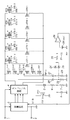
図1は、本発明の第1の実施形態に係る、偶数個の駆動トランスを使用したインバータ回路の回路図である。図1のインバータ回路において、端子1及び端子2間には、直流電源電圧Vinが供給される。直流電源電圧Vinは、制御回路3及びスイッチング回路4に直流動作電源として供給される。
図2は、本発明の第2の実施形態に係る、奇数個の駆動トランスを使用したインバータ回路の回路図である。尚、図2において、同じ回路要素には同じ参照符号を使用している。図2のインバータ回路において、図1のインバータ回路と同様に、端子1及び端子2間には、直流電源電圧Vinが供給される。直流電源電圧Vinは、制御回路3及びスイッチング回路4に直流動作電源として供給される。
3 制御回路
4 スイッチング回路
5、11、24、25 ダイオード
DT1〜DT5 駆動トランス
DT1−1〜DT5−1 駆動トランスの一次巻線
DT1−2〜DT5−2 駆動トランスの二次巻線
CT1〜CT5 バランサトランス
CT1−1〜CT5−1 バランサトランスの一次巻線
CT1−2〜CT5−2 バランサトランスの二次巻線
FBT 帰還トランス
FBT−1 帰還トランスの一次巻線
FBT−2 帰還トランスの二次巻線
14、29 コンパレータ回路
15、28 基準電圧(Vref)
Claims (3)
- 夫々の一次巻線が直列に接続された駆動トランスとバランサトランスの組を複数組設け、複数組の前記直列に接続された一次巻線の両端をスイッチング回路の出力端子間に並列に接続すると共に、前記バランサトランスの全ての二次巻線を直列に接続し、前記スイッチング回路の前記出力端子間に接続して構成される複数の放電灯を駆動するインバータ回路において、
直列に接続された前記バランサトランスの二次巻線のいずれかの接続中点の電圧を検出する電圧検出回路と、
前記電圧検出回路の出力を基準電圧と比較する電圧比較回路と、を備え、
前記接続中点の電圧が前記基準電圧を越えたとき、前記電圧比較回路の出力に異常動作を表す信号を得る、ことを特徴とするインバータ回路。 - 前記電圧比較回路はコンパレータ回路を備え、
前記バランサトランスの二次巻線のいずれかの接続中点の電圧を前記コンパレータ回路の反転入力端子に接続し、
前記基準電圧を前記コンパレータ回路の非反転入力端子に接続する、ことを特徴とする請求項1に記載のインバータ回路。 - スイッチング回路と、
二次巻線に接続された放電灯を駆動する駆動トランスの一次巻線と、バランサトランスの一次巻線を直列に接続したn個(nは2以上の整数)の直列回路と、
前記n個の直列回路に使用されるn個の前記バランサトランスの二次巻線の全てを直列に接続した二次巻線直列回路と、
直列に接続された前記バランサトランスの二次巻線のいずれかの接続中点の電圧と基準電圧とを比較する電圧比較回路と、
前記電圧比較回路により前記接続中点の電圧が前記基準電圧よりも高くなったと検出されると、前記スイッチング回路へのスイッチングパルスの供給を停止する制御回路と、を備え、
前記n個の直列回路と、前記二次巻線直列回路とを、それぞれ前記スイッチング回路の出力端子間に並列に接続した、ことを特徴とするインバータ回路。
Priority Applications (6)
| Application Number | Priority Date | Filing Date | Title |
|---|---|---|---|
| JP2006205260A JP4584880B2 (ja) | 2006-07-27 | 2006-07-27 | インバータ回路 |
| EP07011158.8A EP1885165B1 (en) | 2006-07-27 | 2007-06-06 | Inverter Circuit |
| US11/761,474 US7515443B2 (en) | 2006-07-27 | 2007-06-12 | Inverter circuit |
| TW096122281A TW200808127A (en) | 2006-07-27 | 2007-06-21 | Inverter Circuit |
| KR1020070075083A KR100882001B1 (ko) | 2006-07-27 | 2007-07-26 | 인버터 회로 |
| CN2007101296277A CN101115340B (zh) | 2006-07-27 | 2007-07-27 | 变换器电路 |
Applications Claiming Priority (1)
| Application Number | Priority Date | Filing Date | Title |
|---|---|---|---|
| JP2006205260A JP4584880B2 (ja) | 2006-07-27 | 2006-07-27 | インバータ回路 |
Publications (2)
| Publication Number | Publication Date |
|---|---|
| JP2008034206A JP2008034206A (ja) | 2008-02-14 |
| JP4584880B2 true JP4584880B2 (ja) | 2010-11-24 |
Family
ID=38630095
Family Applications (1)
| Application Number | Title | Priority Date | Filing Date |
|---|---|---|---|
| JP2006205260A Expired - Fee Related JP4584880B2 (ja) | 2006-07-27 | 2006-07-27 | インバータ回路 |
Country Status (6)
| Country | Link |
|---|---|
| US (1) | US7515443B2 (ja) |
| EP (1) | EP1885165B1 (ja) |
| JP (1) | JP4584880B2 (ja) |
| KR (1) | KR100882001B1 (ja) |
| CN (1) | CN101115340B (ja) |
| TW (1) | TW200808127A (ja) |
Families Citing this family (4)
| Publication number | Priority date | Publication date | Assignee | Title |
|---|---|---|---|---|
| US20090059455A1 (en) * | 2007-08-31 | 2009-03-05 | Texas Instruments Incorporated | Method and apparatus for power interruption protection |
| US9770060B2 (en) * | 2013-02-12 | 2017-09-26 | Riddell, Inc. | Pad assemblies for a protective sports helmet |
| EP3818620A4 (en) | 2018-07-19 | 2022-03-23 | MediaTek Singapore Pte. Ltd. | Detecting foreign objects in wireless power transfer systems |
| TWI738029B (zh) | 2018-07-19 | 2021-09-01 | 新加坡商聯發科技(新加坡)私人有限公司 | 無線功率傳輸系統之異物偵測技術 |
Family Cites Families (12)
| Publication number | Priority date | Publication date | Assignee | Title |
|---|---|---|---|---|
| JPS6431394A (en) * | 1987-07-27 | 1989-02-01 | Matsushita Electric Works Ltd | Discharge lamp lighting device |
| ES2340169T3 (es) | 2003-10-06 | 2010-05-31 | Microsemi Corporation | Esquema de distribucion de corrientes y dispositivo para operar multiples lamparas ccf. |
| US7002304B2 (en) * | 2004-01-02 | 2006-02-21 | Lien Chang Electronic Enterprise Co., Ltd. | Multi-lamp drive device |
| US7250731B2 (en) | 2004-04-07 | 2007-07-31 | Microsemi Corporation | Primary side current balancing scheme for multiple CCF lamp operation |
| JP2005310587A (ja) | 2004-04-22 | 2005-11-04 | Hitachi Media Electoronics Co Ltd | 放電ランプ点灯装置 |
| JP4649127B2 (ja) | 2004-06-14 | 2011-03-09 | キヤノン株式会社 | コンデンサ充電回路、撮像装置及びストロボ装置 |
| JP2006066220A (ja) | 2004-08-26 | 2006-03-09 | Mitsumi Electric Co Ltd | 冷陰極管駆動回路 |
| JP2006156338A (ja) | 2004-11-05 | 2006-06-15 | Taiyo Yuden Co Ltd | ランプ点灯装置 |
| JP4529132B2 (ja) | 2004-12-24 | 2010-08-25 | ミネベア株式会社 | 多灯式放電灯点灯装置 |
| US20060244395A1 (en) * | 2005-05-02 | 2006-11-02 | Taipale Mark S | Electronic ballast having missing lamp detection |
| US7271549B2 (en) * | 2005-06-07 | 2007-09-18 | Au Optronics Corporation | Current balancing circuit for a multi-lamp system |
| TWM314499U (en) * | 2006-11-07 | 2007-06-21 | Lite On Technology Corp | Protecton apparatus and multi-lamp driving system using the same |
-
2006
- 2006-07-27 JP JP2006205260A patent/JP4584880B2/ja not_active Expired - Fee Related
-
2007
- 2007-06-06 EP EP07011158.8A patent/EP1885165B1/en not_active Ceased
- 2007-06-12 US US11/761,474 patent/US7515443B2/en not_active Expired - Fee Related
- 2007-06-21 TW TW096122281A patent/TW200808127A/zh not_active IP Right Cessation
- 2007-07-26 KR KR1020070075083A patent/KR100882001B1/ko not_active Expired - Fee Related
- 2007-07-27 CN CN2007101296277A patent/CN101115340B/zh not_active Expired - Fee Related
Also Published As
| Publication number | Publication date |
|---|---|
| CN101115340B (zh) | 2011-11-02 |
| TW200808127A (en) | 2008-02-01 |
| US7515443B2 (en) | 2009-04-07 |
| KR100882001B1 (ko) | 2009-02-04 |
| JP2008034206A (ja) | 2008-02-14 |
| EP1885165A2 (en) | 2008-02-06 |
| EP1885165B1 (en) | 2014-03-26 |
| KR20080011086A (ko) | 2008-01-31 |
| EP1885165A3 (en) | 2009-07-15 |
| US20080025055A1 (en) | 2008-01-31 |
| CN101115340A (zh) | 2008-01-30 |
| TWI372579B (ja) | 2012-09-11 |
Similar Documents
| Publication | Publication Date | Title |
|---|---|---|
| US8502461B2 (en) | Driving circuit and control circuit | |
| US8102124B2 (en) | Inverter circuit for light source | |
| KR100882001B1 (ko) | 인버터 회로 | |
| US9468071B2 (en) | Switching power supply device and projection video display device | |
| JP2012060744A (ja) | 発光素子の駆動回路およびそれを用いた発光装置、電子機器 | |
| CN100558212C (zh) | 液晶显示器件的灯驱动装置及驱动方法 | |
| EP1718132B1 (en) | Load failure protection circuit and discharge lamp driving apparatus | |
| JP2002110388A (ja) | 放電管点灯装置 | |
| US8436540B2 (en) | Multi-lamp driving system | |
| US20120187866A1 (en) | Multi-lamp driving system | |
| JP4421997B2 (ja) | ランプ点灯装置 | |
| KR20090093986A (ko) | 방전등 점등장치 | |
| US20120256557A1 (en) | Multi-lamp driving system | |
| US7781989B2 (en) | Discharge lamp drive control circuit | |
| CN115811028A (zh) | 过压保护电路及照明灯具 | |
| JP4981361B2 (ja) | ランプ点灯装置 | |
| US20070247087A1 (en) | Lamp power supply and protection circuit | |
| KR101735813B1 (ko) | 엘이디 모듈 보호회로 | |
| JPWO2003088722A1 (ja) | 放電灯点灯装置 | |
| TWI442830B (zh) | 多燈管驅動系統 | |
| EP3214901A2 (en) | High-safety led tube | |
| JP2007335216A (ja) | 放電灯点灯装置 | |
| JP2008192390A (ja) | 放電灯点灯装置 |
Legal Events
| Date | Code | Title | Description |
|---|---|---|---|
| A621 | Written request for application examination |
Free format text: JAPANESE INTERMEDIATE CODE: A621 Effective date: 20090602 |
|
| A131 | Notification of reasons for refusal |
Free format text: JAPANESE INTERMEDIATE CODE: A131 Effective date: 20100611 |
|
| A521 | Request for written amendment filed |
Free format text: JAPANESE INTERMEDIATE CODE: A523 Effective date: 20100716 |
|
| TRDD | Decision of grant or rejection written | ||
| A01 | Written decision to grant a patent or to grant a registration (utility model) |
Free format text: JAPANESE INTERMEDIATE CODE: A01 Effective date: 20100820 |
|
| A01 | Written decision to grant a patent or to grant a registration (utility model) |
Free format text: JAPANESE INTERMEDIATE CODE: A01 |
|
| A61 | First payment of annual fees (during grant procedure) |
Free format text: JAPANESE INTERMEDIATE CODE: A61 Effective date: 20100902 |
|
| R150 | Certificate of patent or registration of utility model |
Ref document number: 4584880 Country of ref document: JP Free format text: JAPANESE INTERMEDIATE CODE: R150 Free format text: JAPANESE INTERMEDIATE CODE: R150 |
|
| FPAY | Renewal fee payment (event date is renewal date of database) |
Free format text: PAYMENT UNTIL: 20130910 Year of fee payment: 3 |
|
| R250 | Receipt of annual fees |
Free format text: JAPANESE INTERMEDIATE CODE: R250 |
|
| S531 | Written request for registration of change of domicile |
Free format text: JAPANESE INTERMEDIATE CODE: R313531 |
|
| R350 | Written notification of registration of transfer |
Free format text: JAPANESE INTERMEDIATE CODE: R350 |
|
| R250 | Receipt of annual fees |
Free format text: JAPANESE INTERMEDIATE CODE: R250 |
|
| R250 | Receipt of annual fees |
Free format text: JAPANESE INTERMEDIATE CODE: R250 |
|
| S531 | Written request for registration of change of domicile |
Free format text: JAPANESE INTERMEDIATE CODE: R313531 |
|
| R350 | Written notification of registration of transfer |
Free format text: JAPANESE INTERMEDIATE CODE: R350 |
|
| R250 | Receipt of annual fees |
Free format text: JAPANESE INTERMEDIATE CODE: R250 |
|
| R250 | Receipt of annual fees |
Free format text: JAPANESE INTERMEDIATE CODE: R250 |
|
| R250 | Receipt of annual fees |
Free format text: JAPANESE INTERMEDIATE CODE: R250 |
|
| R250 | Receipt of annual fees |
Free format text: JAPANESE INTERMEDIATE CODE: R250 |
|
| LAPS | Cancellation because of no payment of annual fees |