JP4591107B2 - Control device for internal combustion engine - Google Patents
Control device for internal combustion engine Download PDFInfo
- Publication number
- JP4591107B2 JP4591107B2 JP2005039541A JP2005039541A JP4591107B2 JP 4591107 B2 JP4591107 B2 JP 4591107B2 JP 2005039541 A JP2005039541 A JP 2005039541A JP 2005039541 A JP2005039541 A JP 2005039541A JP 4591107 B2 JP4591107 B2 JP 4591107B2
- Authority
- JP
- Japan
- Prior art keywords
- fuel
- injector
- fuel injection
- injection
- engine
- Prior art date
- Legal status (The legal status is an assumption and is not a legal conclusion. Google has not performed a legal analysis and makes no representation as to the accuracy of the status listed.)
- Expired - Fee Related
Links
Images





Classifications
-
- F—MECHANICAL ENGINEERING; LIGHTING; HEATING; WEAPONS; BLASTING
- F02—COMBUSTION ENGINES; HOT-GAS OR COMBUSTION-PRODUCT ENGINE PLANTS
- F02M—SUPPLYING COMBUSTION ENGINES IN GENERAL WITH COMBUSTIBLE MIXTURES OR CONSTITUENTS THEREOF
- F02M69/00—Low-pressure fuel-injection apparatus ; Apparatus with both continuous and intermittent injection; Apparatus injecting different types of fuel
- F02M69/04—Injectors peculiar thereto
- F02M69/042—Positioning of injectors with respect to engine, e.g. in the air intake conduit
- F02M69/046—Positioning of injectors with respect to engine, e.g. in the air intake conduit for injecting into both the combustion chamber and the intake conduit
-
- F—MECHANICAL ENGINEERING; LIGHTING; HEATING; WEAPONS; BLASTING
- F02—COMBUSTION ENGINES; HOT-GAS OR COMBUSTION-PRODUCT ENGINE PLANTS
- F02D—CONTROLLING COMBUSTION ENGINES
- F02D41/00—Electrical control of supply of combustible mixture or its constituents
- F02D41/30—Controlling fuel injection
- F02D41/3094—Controlling fuel injection the fuel injection being effected by at least two different injectors, e.g. one in the intake manifold and one in the cylinder
-
- F—MECHANICAL ENGINEERING; LIGHTING; HEATING; WEAPONS; BLASTING
- F02—COMBUSTION ENGINES; HOT-GAS OR COMBUSTION-PRODUCT ENGINE PLANTS
- F02M—SUPPLYING COMBUSTION ENGINES IN GENERAL WITH COMBUSTIBLE MIXTURES OR CONSTITUENTS THEREOF
- F02M63/00—Other fuel-injection apparatus having pertinent characteristics not provided for in groups F02M39/00 - F02M57/00 or F02M67/00; Details, component parts, or accessories of fuel-injection apparatus, not provided for in, or of interest apart from, the apparatus of groups F02M39/00 - F02M61/00 or F02M67/00; Combination of fuel pump with other devices, e.g. lubricating oil pump
- F02M63/02—Fuel-injection apparatus having several injectors fed by a common pumping element, or having several pumping elements feeding a common injector; Fuel-injection apparatus having provisions for cutting-out pumps, pumping elements, or injectors; Fuel-injection apparatus having provisions for variably interconnecting pumping elements and injectors alternatively
- F02M63/0225—Fuel-injection apparatus having a common rail feeding several injectors ; Means for varying pressure in common rails; Pumps feeding common rails
- F02M63/0275—Arrangement of common rails
- F02M63/0285—Arrangement of common rails having more than one common rail
- F02M63/029—Arrangement of common rails having more than one common rail per cylinder bank, e.g. storing different fuels or fuels at different pressure levels per cylinder bank
-
- F—MECHANICAL ENGINEERING; LIGHTING; HEATING; WEAPONS; BLASTING
- F02—COMBUSTION ENGINES; HOT-GAS OR COMBUSTION-PRODUCT ENGINE PLANTS
- F02D—CONTROLLING COMBUSTION ENGINES
- F02D13/00—Controlling the engine output power by varying inlet or exhaust valve operating characteristics, e.g. timing
- F02D13/02—Controlling the engine output power by varying inlet or exhaust valve operating characteristics, e.g. timing during engine operation
- F02D13/0261—Controlling the valve overlap
-
- F—MECHANICAL ENGINEERING; LIGHTING; HEATING; WEAPONS; BLASTING
- F02—COMBUSTION ENGINES; HOT-GAS OR COMBUSTION-PRODUCT ENGINE PLANTS
- F02D—CONTROLLING COMBUSTION ENGINES
- F02D2250/00—Engine control related to specific problems or objectives
- F02D2250/08—Engine blow-by from crankcase chamber
-
- F—MECHANICAL ENGINEERING; LIGHTING; HEATING; WEAPONS; BLASTING
- F02—COMBUSTION ENGINES; HOT-GAS OR COMBUSTION-PRODUCT ENGINE PLANTS
- F02M—SUPPLYING COMBUSTION ENGINES IN GENERAL WITH COMBUSTIBLE MIXTURES OR CONSTITUENTS THEREOF
- F02M63/00—Other fuel-injection apparatus having pertinent characteristics not provided for in groups F02M39/00 - F02M57/00 or F02M67/00; Details, component parts, or accessories of fuel-injection apparatus, not provided for in, or of interest apart from, the apparatus of groups F02M39/00 - F02M61/00 or F02M67/00; Combination of fuel pump with other devices, e.g. lubricating oil pump
- F02M63/02—Fuel-injection apparatus having several injectors fed by a common pumping element, or having several pumping elements feeding a common injector; Fuel-injection apparatus having provisions for cutting-out pumps, pumping elements, or injectors; Fuel-injection apparatus having provisions for variably interconnecting pumping elements and injectors alternatively
- F02M63/0225—Fuel-injection apparatus having a common rail feeding several injectors ; Means for varying pressure in common rails; Pumps feeding common rails
Landscapes
- Engineering & Computer Science (AREA)
- Chemical & Material Sciences (AREA)
- Combustion & Propulsion (AREA)
- Mechanical Engineering (AREA)
- General Engineering & Computer Science (AREA)
- Fuel-Injection Apparatus (AREA)
- Output Control And Ontrol Of Special Type Engine (AREA)
- Electrical Control Of Air Or Fuel Supplied To Internal-Combustion Engine (AREA)
- Combined Controls Of Internal Combustion Engines (AREA)
- Lubrication Details And Ventilation Of Internal Combustion Engines (AREA)
Description
本発明は、車両の内燃機関に関し、特に、筒内に向けて燃料を噴射する第1の燃料噴射手段(筒内噴射用インジェクタ)と吸気通路または吸気ポート内に向けて燃料を噴射する第2の燃料噴射手段(吸気通路噴射用インジェクタ)とを備えた内燃機関に関する。 The present invention relates to an internal combustion engine of a vehicle, and in particular, a first fuel injection means (in-cylinder injector) for injecting fuel into a cylinder and a second for injecting fuel into an intake passage or an intake port. The present invention relates to an internal combustion engine provided with a fuel injection means (intake passage injection injector).
機関吸気通路内に燃料を噴射するための吸気通路噴射用インジェクタと、機関燃焼室内に燃料を噴射するための筒内噴射用インジェクタとを具備し、機関負荷が予め定められた設定負荷よりも低いときには吸気通路噴射用インジェクタからの燃料噴射を停止するとともに機関負荷が設定負荷よりも高いときには吸気通路噴射用インジェクタから燃料を噴射するようにした内燃機関が公知である。 An intake passage injector for injecting fuel into the engine intake passage and an in-cylinder injector for injecting fuel into the engine combustion chamber are provided, and the engine load is lower than a predetermined set load There are known internal combustion engines that sometimes stop fuel injection from the intake passage injector and inject fuel from the intake passage injector when the engine load is higher than the set load.
また、このような内燃機関において、可変バルブタイミング機構(VVT(Variable Valve Timing)機構、以下VVT機構と記載することがある)を備える場合がある。このVVT機構は、内燃機関の出力向上を目的として、クランクシャフトに対する吸気カムシャフトや排気カムシャフトの開閉タイミングを可変とする機構である。このような可変バルブタイミング機構は、内燃機関の高回転時にはカムシャフトの回転位相差の調整によりバルブオーバーラップを小から大へ切り替えて出力トルクを向上させ、低回転時にはバルブオーバーラップを大から小へ切り替えて燃焼の安定性を維持させようとするものである。 Such an internal combustion engine may be provided with a variable valve timing mechanism (VVT (Variable Valve Timing) mechanism, hereinafter sometimes referred to as a VVT mechanism). This VVT mechanism is a mechanism that varies the opening / closing timing of the intake camshaft and the exhaust camshaft with respect to the crankshaft for the purpose of improving the output of the internal combustion engine. Such a variable valve timing mechanism improves the output torque by switching the valve overlap from small to large by adjusting the rotational phase difference of the camshaft when the internal combustion engine rotates at high speed, and increases the valve overlap from large to small at low speed. To maintain the stability of combustion.
上述した筒内噴射用インジェクタおよび吸気通路噴射用インジェクタとを備えた内燃機関においてVVT機構が設けられ、バルブオーバーラップが大きいときには、排気の還流(燃えかす等を含む吹き返し分のバックブローガス)が多くなることが考えられる。上記のような筒内噴射用インジェクタと吸気通路噴射用インジェクタとを有する内燃機関において、吸気通路噴射用インジェクタの噴口は通常燃焼室側(吸気通路の下流側)に向けて開口されている。このため、吸気通路噴射用インジェクタからの燃料噴射を停止して、筒内噴射用インジェクタのみから燃料を噴射して内燃機関を運転しているときに、バルブオーバラップが大きくなると、バックブローガスが多くなり、そのバックブローガスが直接吸気通路噴射用インジェクタの噴口に当たるので、バックブローガスに含まれる燃えかす等により、吸気通路噴射用インジェクタの噴口にデポジットを形成する可能性がある。ただし、VVT機構を有さないでも、通常はバルブオーバラップが発生するので、このような吸気通路噴射用インジェクタの噴口にデポジットを形成する可能性がある。 When the VVT mechanism is provided in the internal combustion engine provided with the above-described in-cylinder injector and intake manifold injector, and the valve overlap is large, the exhaust gas recirculation (back blown gas including remnant) is generated. It is possible to increase. In the internal combustion engine having the in-cylinder injector and the intake passage injector as described above, the injection port of the intake passage injector is normally opened toward the combustion chamber side (downstream of the intake passage). Therefore, when fuel injection from the intake manifold injector is stopped and fuel is injected only from the in-cylinder injector and the internal combustion engine is operated, if the valve overlap increases, the back blow gas is Since the back blow gas directly hits the injection port of the intake passage injection injector, deposits may be formed at the injection port of the intake passage injection due to the debris contained in the back blow gas. However, even if the VVT mechanism is not provided, since valve overlap usually occurs, there is a possibility that a deposit is formed at the injection port of such an intake manifold injector.
さらに、内燃機関には、内燃機関のシリンダとピストンの隙間から吹き抜けるガスを大気中に放出せずに、再び吸気マニホールドを通してエンジンに導いて再燃焼させるブローバイガス還元機構が設けられている。ブローバイガスを再燃焼させることにより、炭化水素(HC)の低減が可能となるとともに、NOxの低減および燃費向上の効果が得られる。なお、ブローバイガス還元機構は、PCV(Positive Clankcase Ventilation)機構ともいわれる。以下、ブローバイガスをPCVブローバイガスと記載する場合がある。 Further, the internal combustion engine is provided with a blow-by gas reduction mechanism that does not release the gas blown from the gap between the cylinder and the piston of the internal combustion engine into the atmosphere, but again guides it to the engine through the intake manifold and recombusts it. By recombusting the blow-by gas, it is possible to reduce hydrocarbons (HC) and to obtain effects of reducing NOx and improving fuel consumption. The blow-by gas reduction mechanism is also called a PCV (Positive Clankcase Ventilation) mechanism. Hereinafter, blow-by gas may be referred to as PCV blow-by gas.
上述した筒内噴射用インジェクタおよび吸気通路噴射用インジェクタとを備えた内燃機関においてPCV機構が設けられ、このブローバイガス中のオイル成分等が多い場合には、吸気通路噴射用インジェクタの噴口にこのオイル成分等が付着して、吸気通路噴射用インジェクタの噴口にデポジットを形成する可能性がある。 When the PCV mechanism is provided in the internal combustion engine including the in-cylinder injector and the intake passage injector described above, and the oil component in the blow-by gas is large, the oil is introduced into the injection port of the intake passage injector. There is a possibility that a component or the like adheres to form a deposit at the injection port of the intake manifold injector.
特開平11−294225号公報(特許文献1)は、共用の燃料供給手段から燃料を各気筒へ分配する構成の燃料噴射装置において、低温始動時と高負荷時との双方で燃料供給手段からの燃料の分配が良好に行なうことができる内燃機関の燃料噴射装置を開示する。この内燃機関の燃料噴射装置は、各気筒に接続する吸気通路が分岐形成され、一端側から吸入空気が流入するコレクタを気筒列方向に延設するとともに、コレクタの吸入空気流入側に配設され、始動時には少なくとも吸入気流に対する下流方向に燃料を噴射し、所定の高負荷運転時には少なくとも吸入気流に対する上流方向に燃料を噴射する燃料供給手段を備える。 Japanese Patent Application Laid-Open No. 11-294225 (Patent Document 1) discloses a fuel injection apparatus configured to distribute fuel from a common fuel supply means to each cylinder. Disclosed is a fuel injection device for an internal combustion engine that can perform fuel distribution well. In this fuel injection device for an internal combustion engine, an intake passage connected to each cylinder is branched, and a collector into which intake air flows from one end side extends in the direction of the cylinder row and is disposed on the intake air inflow side of the collector. And a fuel supply means for injecting fuel at least in the downstream direction with respect to the intake airflow during start-up and for injecting fuel at least in the upstream direction with respect to the intake airflow during predetermined high load operation.
この内燃機関の燃料噴射装置によると、始動時、特にクランキング開始直後は、もともとコレクタ内に存在していた空気を各気筒が吸入することになるので、コレクタ上流側から下流方向に燃料噴射を行い、すなわち、もともとコレクタ内に存在していた空気全体に燃料噴霧を混合させることにより、良好な始動性を得ることができる。一方、高負荷運転時は、吸入気流に対向するように上流方向へ噴射することにより、吸入気流の流通断面上の広い範囲に燃料を分散させることが可能となり、吸入気流と燃料噴霧との混合が促進されて各気筒への燃料分配性が良好となる。 According to this fuel injection device for an internal combustion engine, since each cylinder sucks in air that was originally present in the collector at the start, particularly immediately after the start of cranking, fuel injection is performed in the downstream direction from the upstream side of the collector. Good startability can be obtained by doing, ie, mixing the fuel spray with the entire air originally present in the collector. On the other hand, during high-load operation, the fuel can be dispersed over a wide range on the flow cross section of the intake airflow by injecting it upstream so as to face the intake airflow. Is promoted to improve fuel distribution to each cylinder.
特開平1−117908号公報(特許文献2)は、ブローバイガス中のオイルミスト(オイル成分等)が起因する問題を解決する内燃機関のブローバイガス還流装置を開示する。内燃機関のブローバイガス還流装置は、スロットルバルブの直上流にスロットルバルブに向けて噴射口が開口されたインジェクタを有するインジェクションボディが、スロットルボディと一体に構成され、インジェクタを囲むインジェクションボディの空気通路の一側に、ホットワイヤ式のエアフローメータを設置させ、インジェクタを中間にしてエアフローメータと反対側の空気通路にブローバイガス還流通路を連通させるものにおいて、ブローバイガス還流通路の導出口を、インジェクタの噴射口から噴射される燃料の噴射領域より外れた位置で、かつ空気流の動圧が低い個所を選択して、空気流の上流側に向けて開口させるようにインジェクションボディ内の空気通路に突入して設ける。 Japanese Patent Application Laid-Open No. 1-1117908 (Patent Document 2) discloses a blow-by gas recirculation device for an internal combustion engine that solves a problem caused by oil mist (oil component or the like) in blow-by gas. The blow-by gas recirculation device for an internal combustion engine has an injection body having an injector with an injection port opened toward the throttle valve immediately upstream of the throttle valve. The injection body is integrated with the throttle body, and the air passage of the injection body surrounding the injector A hot wire air flow meter is installed on one side, and the blow-by gas recirculation passage is connected to the air passage on the opposite side of the air flow meter with the injector in the middle. Select a location that is out of the injection area of the fuel injected from the mouth and where the dynamic pressure of the air flow is low, and enter the air passage in the injection body so that it opens toward the upstream side of the air flow. Provide.
この内燃機関のブローバイガス還流装置によると、インジェクションボディに形成した空気通路に対してブローバイガスを還流しても、ブローバイガス導出口は、エアフローメータが設置された側と反対側の空気通路に設けているので、還流されるブローバイガス中のオイルミストが、エアフローメータへもたらされることがない。また、ブローバイガス導出口は、インジェクタの噴射口から噴射される燃料の噴射領域より外れた位置であり、かつ空気流の上流側に向けて開口させているので、インジェクタから噴射されるガソリンを、ブローバイガス還流通路に吸い込むことがなくオイルダイリューションを起すおそれがない。さらに、ブローバイガス導出口は、インジェクションボディ内に形成した空気通路に対して空気流の動圧が低い個所に設けているため、空気抵抗になることが可及的に避けられ、相当量のブローバイガスを還流するのに足る大きさを確保できる。
しかしながら、上述した特許文献のいずれもが、筒内噴射用インジェクタおよび吸気通路噴射用インジェクタを有する内燃機関を対象としたものではないので、以下のような問題を解決し得ない。すなわち、
1)吸気通路噴射用インジェクタからの燃料噴射を停止して、筒内噴射用インジェクタのみから燃料を噴射して内燃機関を運転しているときに、バルブオーバラップに起因するバックブローガスにより吸気通路噴射用インジェクタの噴口にデポジットが形成されること、
2)PCV機構におけるブローバイガス中のオイル成分等が多い場合には、吸気通路噴射用インジェクタの噴口にこのオイル成分等が付着して、吸気通路噴射用インジェクタの噴口にデポジットを形成すること、
の2つの問題である。
However, none of the above-described patent documents is directed to an internal combustion engine having an in-cylinder injector and an intake manifold injector, and thus cannot solve the following problems. That is,
1) When the fuel injection from the intake passage injector is stopped and the internal combustion engine is operated by injecting fuel only from the in-cylinder injector, the intake passage is caused by the back blow gas caused by the valve overlap. A deposit is formed at the injection port of the injector for injection;
2) When there is a large amount of oil component or the like in the blow-by gas in the PCV mechanism, the oil component or the like adheres to the injection port of the intake passage injection injector to form a deposit at the injection port of the intake passage injection injector;
There are two problems.
本発明は、上述の課題を解決するためになされたものであって、その目的は、筒内に燃料を噴射する第1の燃料噴射手段と吸気通路に燃料を噴射する第2の燃料噴射手段とで噴射燃料を分担する内燃機関であって、第2の燃料噴射手段の噴口にデポジットが形成されることを抑制することができる、内燃機関の制御装置を提供することである。 The present invention has been made to solve the above-described problems, and has as its object the first fuel injection means for injecting fuel into the cylinder and the second fuel injection means for injecting fuel into the intake passage. And a control device for an internal combustion engine that can suppress the formation of deposits at the injection port of the second fuel injection means.
第1の発明に係る内燃機関の制御装置は、筒内に燃料を噴射するための第1の燃料噴射手段と吸気通路内に燃料を噴射するための第2の燃料噴射手段とを備え、筒内から吸気通路へ燃焼ガスが吹き返す、内燃機関を制御する。この制御装置は、第1の燃料噴射手段および第2の燃料噴射手段の一方の噴射停止を含んで、燃料を分担して噴射するように、燃料噴射手段を制御するための噴射制御手段と、燃焼室から吸気系統への燃焼ガスの吹き返し状態に基づいて、第2の燃料噴射手段から噴射される燃料量を変更するための制御手段とを含む。 According to a first aspect of the present invention, there is provided a control device for an internal combustion engine comprising a first fuel injection means for injecting fuel into a cylinder and a second fuel injection means for injecting fuel into an intake passage. The internal combustion engine is controlled so that the combustion gas blows back from the inside to the intake passage. The control device includes injection control means for controlling the fuel injection means so as to share and inject fuel, including injection stop of one of the first fuel injection means and the second fuel injection means; Control means for changing the amount of fuel injected from the second fuel injection means on the basis of the blow-back state of the combustion gas from the combustion chamber to the intake system.
第1の発明によると、第2の燃料噴射手段(吸気通路噴射用インジェクタ)からの燃料噴射を停止しているときや微小量しか噴射していないときであって、第1の燃料噴射手段(筒内噴射用インジェクタ)から燃料を噴射して内燃機関を運転しているときに、吸排気バルブのオーバラップに起因して発生する燃焼室から吸気系統への燃焼ガスの吹き返しガス(バックブローガス)により、吸気通路噴射用インジェクタの噴口にデポジットが形成されることがある。このために、噴射制御手段では吸気通路噴射用インジェクタからの燃料噴射を指示していないか、指示していても微小量であるが、吸気通路噴射用インジェクタから燃料を増量して噴射して、吸気通路噴射用インジェクタの噴口にデポジットが堆積しないように、バックブローガス中の燃えかす等を吹き飛ばすことができる。その結果、筒内に燃料を噴射する第1の燃料噴射手段と吸気通路に燃料を噴射する第2の燃料噴射手段とで噴射燃料を分担する内燃機関であって、第2の燃料噴射手段の噴口にデポジットが形成されることを抑制することができる、内燃機関の制御装置を提供することができる。 According to the first invention, when the fuel injection from the second fuel injection means (intake passage injection injector) is stopped or when only a minute amount is being injected, the first fuel injection means ( When the internal combustion engine is operated by injecting fuel from an in-cylinder injector), the blow back gas (back blow gas) from the combustion chamber to the intake system generated due to the overlap of the intake and exhaust valves ), A deposit may be formed at the injection port of the intake manifold injector. For this reason, the injection control means does not instruct the fuel injection from the intake passage injection injector, or even if it is instructed, the fuel is injected from the intake passage injection injector while increasing the amount of fuel. In order to prevent deposits from accumulating at the injection port of the intake manifold injector, it is possible to blow off the debris in the back blow gas. As a result, the internal combustion engine shares the injected fuel with the first fuel injection means for injecting fuel into the cylinder and the second fuel injection means for injecting fuel into the intake passage. It is possible to provide a control device for an internal combustion engine that can suppress the formation of deposits at the injection hole.
第2の発明に係る内燃機関の制御装置においては、第1の発明の構成に加えて、制御手段は、噴射制御手段が第2の燃料噴射手段の噴射を停止させているときに、第2の燃料噴射手段から燃料を噴射するための手段を含む。 In the control apparatus for an internal combustion engine according to the second aspect of the invention, in addition to the configuration of the first aspect, the control means includes the second means when the injection control means stops the injection of the second fuel injection means. Means for injecting fuel from the fuel injection means.
第2の発明によると、第2の燃料噴射手段(吸気通路噴射用インジェクタ)からの燃料噴射を停止して、第1の燃料噴射手段(筒内噴射用インジェクタ)のみから燃料を噴射して内燃機関を運転しているときに、吸排気バルブのオーバラップに起因して発生する燃焼室から吸気系統への燃焼ガスの吹き返しガス(バックブローガス)により、吸気通路噴射用インジェクタの噴口にデポジットが形成されることがある。このために、噴射制御手段では吸気通路噴射用インジェクタからの燃料噴射を指示していないが、吸気通路噴射用インジェクタから燃料を噴射して、吸気通路噴射用インジェクタの噴口にデポジットが堆積しないように、バックブローガス中の燃えかす等を吹き飛ばすことができる。 According to the second invention, the fuel injection from the second fuel injection means (intake passage injection injector) is stopped, and the fuel is injected only from the first fuel injection means (in-cylinder injector) to generate internal combustion. When the engine is operating, deposits are generated at the injection port of the intake manifold injector due to the blowback gas (back blow gas) of the combustion gas from the combustion chamber to the intake system generated due to the overlap of the intake and exhaust valves. Sometimes formed. For this reason, the injection control means does not instruct fuel injection from the intake passage injection injector, but fuel is injected from the intake passage injection injector so that deposits do not accumulate at the injection port of the intake passage injection injector. It is possible to blow off the debris in the back blow gas.
第3の発明に係る内燃機関の制御装置においては、第1または2の発明の構成に加えて、内燃機関には可変バルブタイミング機構が設けられる。制御手段は、可変バルブタイミング機構のバルブオーバラップ量を検知して、検知されたバルブオーバラップ量に基づいて、第2の燃料噴射手段から燃料を噴射するための手段を含む。 In the control apparatus for an internal combustion engine according to the third invention, in addition to the configuration of the first or second invention, the internal combustion engine is provided with a variable valve timing mechanism. The control means includes means for detecting a valve overlap amount of the variable valve timing mechanism and injecting fuel from the second fuel injection means based on the detected valve overlap amount.
第3の発明によると、VVTバルブタイミング機構により吸排気バルブのオーバラップ量が大きいほどバックブローガスの量も大きくなる。このため、たとえば、バルブオーバラップ量が大きいほど、より長く、あるいはより多く、吸気通路噴射用インジェクタから燃料を噴射することにより、吸気通路噴射用インジェクタの噴口にデポジットが堆積しないように、バックブローガス中の燃えかす等を吹き飛ばすことができる。 According to the third invention, the amount of the back blow gas increases as the overlap amount of the intake and exhaust valves increases by the VVT valve timing mechanism. For this reason, for example, the larger the valve overlap amount, the longer or the more fuel is injected from the intake manifold injector so that deposits do not accumulate at the injection port of the intake manifold injector. It is possible to blow off the scum in the gas.
第4の発明に係る内燃機関の制御装置においては、第3の発明の構成に加えて、制御手段は、可変バルブタイミング機構のバルブオーバラップ量が予め定められたしきい値よりも大きいと、第2の燃料噴射手段から燃料を噴射するための手段を含む。 In the control apparatus for an internal combustion engine according to the fourth invention, in addition to the configuration of the third invention, the control means, when the valve overlap amount of the variable valve timing mechanism is larger than a predetermined threshold value, Means for injecting fuel from the second fuel injection means;
第4の発明によると、VVTバルブタイミング機構により吸排気バルブのオーバラップ量が予め定められたしきい値よりも大きいと、吸気通路噴射用インジェクタの噴口にデポジットが堆積する可能性が高いので、吸気通路噴射用インジェクタから燃料を噴射することにより、吸気通路噴射用インジェクタの噴口にデポジットが堆積することを防止できる。 According to the fourth invention, if the overlap amount of the intake and exhaust valves is larger than a predetermined threshold value by the VVT valve timing mechanism, there is a high possibility that deposits are accumulated at the injection port of the intake passage injector. By injecting fuel from the intake manifold injector, it is possible to prevent deposits from depositing at the injection port of the intake manifold injector.
第5の発明に係る内燃機関の制御装置は、筒内に燃料を噴射するための第1の燃料噴射手段と吸気通路内に燃料を噴射するための第2の燃料噴射手段とを備え、ブローバイガスが第2の燃料噴射手段よりも上流側の吸気通路内に還流される、内燃機関を制御する。この制御装置は、第1の燃料噴射手段および第2の燃料噴射手段の一方の噴射停止を含んで、燃料を分担して噴射するように、燃料噴射手段を制御するための噴射制御手段と、還流されるブローバイガスの状態に基づいて、第2の燃料噴射手段から噴射される燃料量を変更するための制御手段とを含む。 A control device for an internal combustion engine according to a fifth aspect of the present invention comprises a first fuel injection means for injecting fuel into a cylinder and a second fuel injection means for injecting fuel into an intake passage. The internal combustion engine is controlled such that the gas is recirculated into the intake passage upstream of the second fuel injection means. The control device includes injection control means for controlling the fuel injection means so as to share and inject fuel, including injection stop of one of the first fuel injection means and the second fuel injection means; Control means for changing the amount of fuel injected from the second fuel injection means based on the state of the blow-by gas being refluxed.
第5の発明によると、第2の燃料噴射手段(吸気通路噴射用インジェクタ)からの燃料噴射を停止しているときや微小量しか噴射していないときであって、第1の燃料噴射手段(筒内噴射用インジェクタ)から燃料を噴射して内燃機関を運転しているときに、ブローバイガスに含まれるオイル成分等により、吸気通路噴射用インジェクタの噴口が汚損されたり、さらにその汚損から噴口にデポジットが形成されることがある。このために、噴射制御手段では吸気通路噴射用インジェクタからの燃料噴射を指示していないか、指示していても微小量であるが、吸気通路噴射用インジェクタから燃料を増量して噴射して、吸気通路噴射用インジェクタの噴口にデポジットが堆積しないように、ブローバイガス中のオイル成分等を吹き飛ばすことができる。その結果、筒内に燃料を噴射する第1の燃料噴射手段と吸気通路に燃料を噴射する第2の燃料噴射手段とで噴射燃料を分担する内燃機関であって、第2の燃料噴射手段の噴口にデポジットが形成されることを抑制することができる、内燃機関の制御装置を提供することができる。 According to the fifth invention, when the fuel injection from the second fuel injection means (intake passage injection injector) is stopped or when only a minute amount is being injected, the first fuel injection means ( When an internal combustion engine is operated by injecting fuel from an in-cylinder injector), the inlet of the intake manifold injector is contaminated by the oil component contained in the blow-by gas, and further from the contamination to the nozzle Deposits may be formed. For this reason, the injection control means does not instruct the fuel injection from the intake passage injection injector, or even if it is instructed, the fuel is injected from the intake passage injection injector while increasing the amount of fuel. Oil components and the like in the blow-by gas can be blown away so that deposits do not accumulate at the injection port of the intake manifold injector. As a result, the internal combustion engine shares the injected fuel with the first fuel injection means for injecting fuel into the cylinder and the second fuel injection means for injecting fuel into the intake passage. It is possible to provide a control device for an internal combustion engine that can suppress the formation of deposits at the injection hole.
第6の発明に係る内燃機関の制御装置においては、第5の発明の構成に加えて、制御手段は、噴射制御手段が第2の燃料噴射手段の噴射を停止させているときに、第2の燃料噴射手段から燃料を噴射するための手段を含む。 In the control apparatus for an internal combustion engine according to the sixth aspect of the invention, in addition to the configuration of the fifth aspect of the invention, the control means includes the second means when the injection control means stops the injection of the second fuel injection means. Means for injecting fuel from the fuel injection means.
第6の発明によると、第2の燃料噴射手段(吸気通路噴射用インジェクタ)からの燃料噴射を停止して、第1の燃料噴射手段(筒内噴射用インジェクタ)のみから燃料を噴射して内燃機関を運転しているときに、ブローバイガスに含まれるオイル成分等により、吸気通路噴射用インジェクタの噴口が汚損されたり、さらにその汚損から噴口にデポジットが形成されることがある。このために、噴射制御手段では吸気通路噴射用インジェクタからの燃料噴射を指示していないが、吸気通路噴射用インジェクタから燃料を噴射して、吸気通路噴射用インジェクタの噴口にデポジットが堆積しないように、ブローバイガス中のオイル成分等を吹き飛ばすことができる。 According to the sixth aspect of the invention, the fuel injection from the second fuel injection means (intake passage injection injector) is stopped, and the fuel is injected only from the first fuel injection means (in-cylinder injection injector). When the engine is in operation, the injection port injection port nozzle may be fouled by the oil component or the like contained in the blow-by gas, and deposits may be formed at the nozzle port due to the fouling. For this reason, the injection control means does not instruct fuel injection from the intake passage injection injector, but fuel is injected from the intake passage injection injector so that deposits do not accumulate at the injection port of the intake passage injection injector. The oil component in the blow-by gas can be blown off.
第7の発明に係る内燃機関の制御装置においては、第5または6の発明の構成に加えて、制御手段は、還流されるブローバイガス中のオイル成分量を推定して、推定されたオイル成分量に基づいて、第2の燃料噴射手段から燃料を噴射するための手段を含む。 In the control apparatus for an internal combustion engine according to the seventh invention, in addition to the structure of the fifth or sixth invention, the control means estimates the amount of oil component in the blow-by gas to be recirculated, and the estimated oil component Based on the quantity, includes means for injecting fuel from the second fuel injection means.
第7の発明によると、ブローバイガス中のオイル成分等が大きくなる。このため、たとえば、ブローバイガス中のオイル成分量が大きいほど、より長く、あるいはより多く、吸気通路噴射用インジェクタから燃料を噴射することにより、吸気通路噴射用インジェクタの噴口にデポジットが堆積しないように、ブローバイガス中のオイル成分等を吹き飛ばすことができる。 According to the seventh aspect, the oil component and the like in the blow-by gas is increased. For this reason, for example, as the amount of the oil component in the blow-by gas is larger, the fuel is injected from the intake passage injection injector longer or more so that deposits do not accumulate at the injection port of the intake passage injection injector. The oil component in the blow-by gas can be blown off.
第8の発明に係る内燃機関の制御装置においては、第7の発明の構成に加えて、制御手段は、還流されるブローバイガス中のオイル成分量を推定して、推定されたオイル成分量が予め定められたしきい値よりも大きいと、第2の燃料噴射手段から燃料を噴射するための手段を含む。 In the control apparatus for an internal combustion engine according to the eighth invention, in addition to the configuration of the seventh invention, the control means estimates the amount of oil component in the refluxed blowby gas, and the estimated amount of oil component is Means for injecting fuel from the second fuel injection means when greater than a predetermined threshold value are included.
第8の発明によると、ブローバイガス中のオイル成分量が予め定められたしきい値よりも大きいと、吸気通路噴射用インジェクタの噴口にデポジットが堆積する可能性が高いので、吸気通路噴射用インジェクタから燃料を噴射することにより、吸気通路噴射用インジェクタの噴口にデポジットが堆積することを防止できる。 According to the eighth aspect of the invention, if the amount of oil component in the blow-by gas is larger than a predetermined threshold value, there is a high possibility that deposits will accumulate at the injection port of the intake passage injection injector. It is possible to prevent deposits from being deposited at the injection port of the intake manifold injector by injecting the fuel from the intake.
第9の発明に係る内燃機関の制御装置においては、第1〜8のいずれかの発明の構成に加えて、噴射制御手段は、制御手段により第2の燃料噴射手段により噴射される燃料の増量分を、第1の燃料噴射手段から噴射される燃料から減量して噴射するように、第1の燃料噴射手段を制御するための手段を含む。 In the control device for an internal combustion engine according to the ninth invention, in addition to the configuration of any one of the first to eighth inventions, the injection control means increases the amount of fuel injected by the second fuel injection means by the control means. Means for controlling the first fuel injection means to inject the fuel from the fuel injected from the first fuel injection means in a reduced amount.
第9の発明によると、筒内噴射用インジェクタからの噴射燃料量を、吸気通路噴射用インジェクタで増量した燃料分だけ減量して、内燃機関に供給される総燃料量を大きく変化させないで、内燃機関の運転状態を所望の状態に維持できる。 According to the ninth aspect of the present invention, the amount of fuel injected from the in-cylinder injector is decreased by the amount of fuel increased by the intake manifold injector, and the total amount of fuel supplied to the internal combustion engine is not greatly changed. The operating state of the engine can be maintained in a desired state.
第10の発明に係る内燃機関の制御装置においては、第1〜9のいずれかの発明の構成に加えて、第2の燃料噴射手段は、吸気通路の上流に向けて燃料を噴射するための手段を含む。 In the control apparatus for an internal combustion engine according to the tenth invention, in addition to the configuration of any one of the first to ninth inventions, the second fuel injection means is for injecting fuel upstream of the intake passage. Including means.
第10の発明によると、吸気通路噴射用インジェクタは燃焼室側ではなく吸気通路の上流側に向けて燃料を噴射する。このため、バックブローガスが直接噴口に当たることがなくなり、バックブローガス中に含まれる燃えかす等によるデポジット形成を抑制できる。また、吸気通路噴射用インジェクタから噴射された燃料気流と、吸気気流とが互いに干渉して、混合気の霧化を促進できる。 According to the tenth invention, the intake manifold injector injects fuel not to the combustion chamber but to the upstream side of the intake manifold. For this reason, the back blow gas does not directly hit the nozzle hole, and deposit formation due to debris contained in the back blow gas can be suppressed. Further, the fuel airflow injected from the intake manifold injector and the intake airflow interfere with each other, and the atomization of the air-fuel mixture can be promoted.
第11の発明に係る内燃機関の制御装置においては、第1〜9のいずれかの発明の構成に加えて、第2の燃料噴射手段における燃料噴射方向は、第2の燃料噴射手段の噴口から吸気通路の中心線に対して引いた垂線よりも上流側に設定されるものである。 In the control apparatus for an internal combustion engine according to the eleventh invention, in addition to the configuration of any one of the first to ninth inventions, the fuel injection direction in the second fuel injection means is from the injection hole of the second fuel injection means. It is set on the upstream side of the perpendicular drawn with respect to the center line of the intake passage.
第11の発明によると、吸気通路噴射用インジェクタの噴口から吸気通路の中心線に対して引いた垂線よりも上流側に、吸気通路噴射用インジェクタの噴射方向が設定される。これにより、バックブローガスが直接噴口に当たることがなくなる。 According to the eleventh aspect of the invention, the injection direction of the intake passage injector is set upstream of the perpendicular drawn from the injection port of the intake passage injector to the center line of the intake passage. As a result, the back blow gas does not directly hit the nozzle.
第12の発明に係る内燃機関の制御装置においては、第1〜11のいずれかの発明の構成に加えて、第1の燃料噴射手段は、筒内噴射用インジェクタであって、第2の燃料噴射手段は、吸気通路用インジェクタである。 In the control device for an internal combustion engine according to the twelfth invention, in addition to the configuration of any one of the first to eleventh inventions, the first fuel injection means is an in-cylinder injector, and the second fuel The injection means is an intake passage injector.
第12の発明によると、第1の燃料噴射手段である筒内噴射用インジェクタと第2の燃料噴射手段である吸気通路噴射用インジェクタとを別個に設けて噴射燃料を分担する内燃機関において、吸気通路噴射用インジェクタの噴口にデポジットが形成されることを抑制できる。 According to a twelfth aspect of the present invention, in the internal combustion engine that shares the injected fuel by separately providing the in-cylinder injector that is the first fuel injection means and the intake passage injection injector that is the second fuel injection means, It is possible to suppress the formation of deposits at the injection port of the passage injection injector.
以下、図面を参照しつつ、本発明の実施の形態について説明する。以下の説明では、同一の部品には同一の符号を付してある。それらの名称および機能も同じである。したがってそれらについての詳細な説明は繰返さない。 Hereinafter, embodiments of the present invention will be described with reference to the drawings. In the following description, the same parts are denoted by the same reference numerals. Their names and functions are also the same. Therefore, detailed description thereof will not be repeated.
<第1の実施の形態>
図1に、本発明の実施の形態に係る内燃機関の制御装置であるエンジンECU(Electronic Control Unit)で制御されるエンジンシステムの概略構成図を示す。なお、図1には、エンジンとして直列4気筒ガソリンエンジンを示すが、本発明はこのようなエンジンに限定されるものではない。
<First Embodiment>
FIG. 1 shows a schematic configuration diagram of an engine system controlled by an engine ECU (Electronic Control Unit) which is a control device for an internal combustion engine according to an embodiment of the present invention. Although FIG. 1 shows an in-line four-cylinder gasoline engine as the engine, the present invention is not limited to such an engine.
図1に示すように、エンジン10は、4つの気筒112を備え、各気筒112はそれぞれ対応するインテークマニホールド20を介して共通のサージタンク30に接続されている。サージタンク30は、吸気ダクト40を介してエアクリーナ50に接続され、吸気ダクト40内にはエアフローメータ42が配置されるとともに、電動モータ60によって駆動されるスロットルバルブ70が配置されている。このスロットルバルブ70は、アクセルペダル100とは独立してエンジンECU(Electronic Control Unit)300の出力信号に基づいてその開度が制御される。一方、各気筒112は共通のエキゾーストマニホールド80に連結され、このエキゾーストマニホールド80は三元触媒コンバータ90に連結されている。
As shown in FIG. 1, the
各気筒112に対しては、筒内に向けて燃料を噴射するための筒内噴射用インジェクタ110と、吸気ポートまたは/および吸気通路内に向けて燃料を噴射するための吸気通路噴射用インジェクタ120とがそれぞれ設けられている。これらインジェクタ110、120はエンジンECU300の出力信号に基づいてそれぞれ制御される。また、各気筒内噴射用インジェクタ110は共通の燃料分配管130に接続されており、この燃料分配管130は燃料分配管130に向けて流通可能な逆止弁140を介して、機関駆動式の高圧燃料ポンプ150に接続されている。なお、本実施の形態においては、2つのインジェクタが別個に設けられた内燃機関について説明するが、本発明はこのような内燃機関に限定されない。たとえば、筒内噴射機能と吸気通路噴射機能とを併せ持つような1個のインジェクタを有する内燃機関であってもよい。
For each
図1に示すように、高圧燃料ポンプ150の吐出側は電磁スピル弁152を介して高圧燃料ポンプ150の吸入側に連結されており、この電磁スピル弁152の開度が小さいときほど、高圧燃料ポンプ150から燃料分配管130内に供給される燃料量が増大され、電磁スピル弁152が全開にされると、高圧燃料ポンプ150から燃料分配管130への燃料供給が停止されるように構成されている。なお、電磁スピル弁152はエンジンECU300の出力信号に基づいて制御される。
As shown in FIG. 1, the discharge side of the high-
一方、各吸気通路噴射用インジェクタ120は、共通する低圧側の燃料分配管160に接続されており、燃料分配管160および高圧燃料ポンプ150は共通の燃料圧レギュレータ170を介して、電動モータ駆動式の低圧燃料ポンプ180に接続されている。さらに、低圧燃料ポンプ180は燃料フィルタ190を介して燃料タンク200に接続されている。燃料圧レギュレータ170は低圧燃料ポンプ180から吐出された燃料の燃料圧が予め定められた設定燃料圧よりも高くなると、低圧燃料ポンプ180から吐出された燃料の一部を燃料タンク200に戻すように構成されており、したがって吸気通路噴射用インジェクタ120に供給されている燃料圧および高圧燃料ポンプ150に供給されている燃料圧が上記設定燃料圧よりも高くなるのを阻止している。
On the other hand, each
エンジンECU300は、デジタルコンピュータから構成され、双方向性バス310を介して相互に接続されたROM(Read Only Memory)320、RAM(Random Access Memory)330、CPU(Central Processing Unit)340、入力ポート350および出力ポート360を備えている。
The
エアフローメータ42は吸入空気量に比例した出力電圧を発生し、このエアフローメータ42の出力電圧はA/D変換器370を介して入力ポート350に入力される。エンジン10には機関冷却水温に比例した出力電圧を発生する水温センサ380が取付けられ、この水温センサ380の出力電圧は、A/D変換器390を介して入力ポート350に入力される。
The air flow meter 42 generates an output voltage proportional to the amount of intake air, and the output voltage of the air flow meter 42 is input to the
燃料分配管130には燃料分配管130内の燃料圧に比例した出力電圧を発生する燃料圧センサ400が取付けられ、この燃料圧センサ400の出力電圧は、A/D変換器410を介して入力ポート350に入力される。三元触媒コンバータ90上流のエキゾーストマニホールド80には、排気ガス中の酸素濃度に比例した出力電圧を発生する空燃比センサ420が取付けられ、この空燃比センサ420の出力電圧は、A/D変換器430を介して入力ポート350に入力される。
A
本実施の形態に係るエンジンシステムにおける空燃比センサ420は、エンジン10で燃焼された混合気の空燃比に比例した出力電圧を発生する全域空燃比センサ(リニア空燃比センサ)である。なお、空燃比センサ420としては、エンジン10で燃焼された混合気の空燃比が理論空燃比に対してリッチであるかリーンであるかをオン−オフ的に検出するO2センサを用いてもよい。
The air-
アクセルペダル100は、アクセルペダル100の踏込み量に比例した出力電圧を発生するアクセル開度センサ440に接続され、アクセル開度センサ440の出力電圧は、A/D変換器450を介して入力ポート350に入力される。また、入力ポート350には、機関回転数を表わす出力パルスを発生する回転数センサ460が接続されている。エンジンECU300のROM320には、上述のアクセル開度センサ440および回転数センサ460により得られる機関負荷率および機関回転数に基づき、運転状態に対応させて設定されている燃料噴射量の値や機関冷却水温に基づく補正値などが予めマップ化されて記憶されている。
The
図2に、図1の部分拡大図を示す。図2は、図1の各気筒112における筒内噴射用インジェクタ110および吸気通路噴射用インジェクタ120の位置関係、ならびにインテークマニホールド20、吸気バルブ122、排気バルブ121、点火プラグ119およびピストン123の位置関係を説明する図である。
FIG. 2 shows a partially enlarged view of FIG. 2 shows the positional relationship between the in-
インテークマニホールド20の燃焼室側には吸気バルブ122が設けられており、その吸気バルブ122の上流側に吸気通路噴射用インジェクタ120が配置されている。吸気通路噴射用インジェクタ120は、吸気通路であるインテークマニホールド20の上流側の内壁に向けて燃料を噴射する。この吸気通路噴射用インジェクタ120の燃料噴射方向については、以下のようにすることが考えられる。
An
このインテークマニホールド20には、吸気バルブ122と、排気バルブ121とのオーバーラップにより燃焼室内の燃えかす等が逆流する。吸気通路噴射用インジェクタ120の噴口を下流側(燃焼室側)に向けると、この燃えかす等により吸気通路噴射用インジェクタの噴口にデポジットが形成する可能性がある。このため、吸気通路噴射用インジェクタ120の燃料噴射方向(噴口)は、燃料室とは逆側の上流側に向けられている。
In the
より詳しくは、吸気通路噴射用インジェクタ120からの燃料噴射方向を吸気通路噴射用インジェクタ120の噴口から吸気通路であるインテークマニホールド20の中心線に対して引いた垂線よりも上流側に設定される。このようにすると、吸気通路噴射用インジェクタ120の噴口が燃焼室に向いていないので吸気通路噴射用インジェクタ120の噴口に燃えかす等が堆積することによるデポジットの形成が抑制される。また、吸気上流に向けて、吸気通路噴射用インジェクタ120から燃料を噴射するので、燃料噴射方向と吸気方向とが逆方向になり、噴射燃料と吸気空気とが干渉し合い混合気の霧化が促進される。
More specifically, the fuel injection direction from the
また、図2に示すように、ピストン123の頂部には、筒内噴射用インジェクタ110に対向する位置に緩やかな曲線から形成されるくぼみが設けられている。このくぼみに向けて筒内噴射用インジェクタ110から燃料が噴射される。このとき、筒内噴射用インジェクタ110に対向するピストン123の頂部は角部を有しないので、筒内噴射用インジェクタ110から噴射された燃料により形成された噴霧が角部により分裂されることがない。このような分裂があるとローカルリッチの状態になる場合があり得るが、そのような状態になることを回避できる。なお、ピストン123の頂部はこのような形状に限定されるものではない。
Further, as shown in FIG. 2, a depression formed by a gentle curve is provided at the top of the
なお、図2に示すように配置された筒内噴射用インジェクタ110と吸気通路噴射用インジェクタ120との燃料分担比率の詳細については、後述する。
The details of the fuel sharing ratio between the in-
本実施の形態においては、図2を用いて説明したように、吸気通路噴射用インジェクタ112の噴口を上流側に向けている。そのため、VVT装置によるバルブオーバラップ量が大きいとバックブローガスが燃焼室から吸気系統に入り込む。バックブローガスが燃えかす等を含む場合には、吸気通路噴射用インジェクタ120の噴口にデポジットが形成されるおそれがある。特に、エンジン10が筒内噴射用インジェクタ110のみで運転しており、吸気通路噴射用インジェクタ110から燃料を噴射していないときに、吸気通路噴射用インジェクタ120の噴口から燃料を噴射していないので、デポジットが堆積されるおそれが強い。そのため、本実施の形態に係る制御装置であるエンジンECU300においては、筒内噴射用インジェクタ110のみから燃料を噴射してエンジン10を運転しているときにVVTオーバラップ量が大きいと、吸気通路噴射用インジェクタ120から燃料を噴射して、バックブローガス中の燃えかす等によるデポジット形成を防止することが特徴である。
In the present embodiment, as described with reference to FIG. 2, the injection port of the
図3を参照して、本実施の形態に係る制御装置であるエンジンECU300において実行されるプログラムの制御構造について説明する。
With reference to FIG. 3, a control structure of a program executed in
S100にて、エンジンECU300は、詳しくは後述するように、筒内噴射用インジェクタ110と吸気通路噴射用インジェクタ120との分担比率を算出する。これは、全噴射燃料の中の筒内噴射用インジェクタ110で噴射する燃料の比率として、噴き分け比率(以下、DI比率rと記載する場合がある)として算出される。
In S100,
S110にて、エンジンECU300は、DI比率rが1であるか否かを判断する。すなわち、筒内噴射用インジェクタ110のみから燃料を噴射するか否かを判断する。DI比率rが1であると(S110にてYES)、処理はS120へ移される。もしそうでないと(S110にてNO)、この処理は終了する。
In S110,
S120にて、エンジンECU300は、吸気バルブ122と排気バルブ123とのVVTバルブオーバラップ量を検知する。S130にて、エンジンECU300は、検知されたVVTオーバラップ量がしきい値以上であるか否かを判断する。検知されたVVTオーバラップ量がしきい値以上であると(S130にてYES)、処理はS140へ移される。もしそうでないと(S130にてNO)、この処理は終了する。なお、エンジン10がVVT装置を有さないで、バルブオーバラップを有する場合にはこのS120およびS130の処理は不要である。
In S120,
S140にて、エンジンECU300は、吸気通路噴射用インジェクタ120から燃料を噴射する。このとき、間欠噴射であっても、連続噴射であっても構わない。ただし、吸気通路噴射用インジェクタ120から噴射された燃料はエンジン10の燃焼室内に導入されるので、筒内噴射用インジェクタ110の燃料噴射量を減量する等の処理を行なうことが好ましい。
In S140,
以上のような構造およびフローチャートに基づく、本実施の形態に係る制御装置であるエンジンECU300により制御されるエンジンシステムの動作について説明する。
The operation of the engine system controlled by
筒内噴射用インジェクタ110および吸気通路噴射用インジェクタ120を備えたエンジン10の運転中においては、詳しくは後述するように、筒内噴射用インジェクタ110と吸気通路噴射用インジェクタ120との分担比率が算出される。これは、全噴射燃料の中の筒内噴射用インジェクタ110で噴射する燃料の比率として、噴き分け比率(DI比率r)として算出される(S110)。
During operation of the
DI比率rが1の場合(すなわち、エンジン10の燃焼室に供給される全燃料量が筒内噴射用インジェクタ110から噴射される場合)、エンジン10の運転状態に基づいて、VVTバルブオーバラップ量が検知される(S120)。
When the DI ratio r is 1 (that is, when the total amount of fuel supplied to the combustion chamber of the
検知されたVVTバルブオーバラップ量がしきい値以上であると(S130にてYES)、吸気通路噴射用インジェクタ120から燃料を噴射して吸気通路噴射用インジェクタ120の噴口にバックブローガス中に含まれる燃えかす等による吸気通路噴射用インジェクタのデポジットの形成を回避する。
If the detected VVT valve overlap amount is equal to or greater than the threshold value (YES in S130), fuel is injected from
以上のようにして、筒内噴射用インジェクタと吸気通路噴射用インジェクタとを有するエンジンにおいて、吸気バルブと排気バルブとのオーバラップにより燃焼室から吸気系統にバックブローガスが逆流する場合、バックブローガス中に含まれる燃えかす等により吸気通路噴射用インジェクタの噴口にデポジットを形成するおそれがある。そのため、算出された噴き分けとは関係なく、吸気通路噴射用インジェクタから燃料を噴射して吸気通路噴射用インジェクタの噴口にデポジットが形成されることを抑制できる。 As described above, in an engine having an in-cylinder injector and an intake manifold injector, when the back blow gas flows backward from the combustion chamber to the intake system due to the overlap of the intake valve and the exhaust valve, the back blow gas There is a risk that deposits may be formed at the injection port of the intake manifold injector due to debris contained therein. Therefore, it is possible to suppress the formation of deposits at the injection port of the intake passage injection injector by injecting fuel from the intake passage injection injector regardless of the calculated injection division.
なお、上述のように吸気通路噴射用インジェクタ120から燃料を噴射することに対応させて、この吸気通路噴射用インジェクタ120から噴射された燃料量分だけ筒内噴射用インジェクタ110からの燃料噴射量を減量させる補正を行なうことも、燃焼室内の混合気の空燃比制御にとって有意義である。さらに、このときにエンジン10の温度等に基づいて吸気通路噴射用インジェクタ120から噴射された燃料の壁面付着量(燃焼室に導入されない量)を考慮して、筒内噴射用インジェクタ110からの燃料噴射量を減量させる補正を行なうことも有意義である。
In correspondence with the fuel injection from the
<第2の実施の形態>
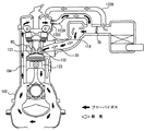
図4を参照して、本実施の形態に係るエンジン制御システムが制御する、PCV装置が実装されたエンジン10の断面について説明する。図4には、エンジン10の軽負荷時の状態を示す。
<Second Embodiment>
With reference to FIG. 4, a cross section of
図4に示すように、このエンジン10は、主として、シリンダ104と、ピストン123と、クランクケース102と、シリンダヘッド116とから構成される。PCVブローバイガスは、ピストンリングとシリンダ104との隙間からクランクケース102へ漏れる混合ガスのことであって、このPCVブローバイガスには多量の炭化水素や水分が含まれており、かつ強酸性であるため、あまり多いとエンジンオイルの劣化やエンジン内部の錆の原因になる。また、炭化水素が含まれているため、このまま大気に解放することは環境によくない。そのため、PCVブローバイガスはPCV管路122A(軽負荷時)、PCV管路122AおよびPCV管路122B(高負荷時)を通して、インテークマニホールド20の負圧を利用して強制的に吸気系統へ戻されることになる。この軽負荷時におけるPCVブローバイガスおよび新気の流れを矢印で示す。
As shown in FIG. 4, the
軽負荷時においては、スロットルバルブ70が閉じる傾向に制御されており、スロットルバルブ70下流側のシリンダヘッド116側の負圧が大きくなっているので、PCV管路122Bを通って新気が導入される。PCV管路122Bを通って導入された新気はPCVブローバイガスと混合されて、PCVバルブ122CおよびPCV管路122Aを通って燃焼室に供給される。
When the load is light, the
吸気系にはスロットルバルブ70が設けられている。スロットルバルブ70にてエンジン10へ供給される吸気の量が調整され、インテークマニホールド20を、その量が調整された吸気が通って吸気バルブ122からエンジン10の内部の燃焼室に供給される。供給された吸気により燃料が燃焼され、排気バルブ121およびエキゾーストマニホールド80を介して燃焼ガスがエンジン外部に排出される。
A
ピストンリングとシリンダ104との隙間で発生したPCVブローバイガスは、シリンダヘッド116内を通り、軽負荷時にはPCV管路122Aを通って、高負荷時にはPCV管路122AおよびPCV管路122Bを通ってインテークマニホールド20へと導かれる。PCV管路122Aには、PCVバルブ122Cが設けられている。このPCVバルブ122Cは、インテークマニホールド20における負圧により、PCV流量が調整されるバルブであって、すなわち、図1に示すように、PCV管路122Aは、PCVバルブ122Cによりその流量が調節されてスロットルバルブ70の下流側にPCVブローバイガスを還元する。エンジン10の高負荷時において、スロットルバルブ70の開度が大きくなり負圧が高まるので、PCV管路122Bには、スロットルバルブ70の上流側に供給されるPCVブローバイガスが流されて、PCVブローバイガスが還元される。
The PCV blow-by gas generated in the gap between the piston ring and the
また、スロットルバルブ70は、エンジンECU300からの制御デューティ信号により、その開度が調整される電磁弁であって、その開度によりエンジンに供給される流量が調節される。
The
さらに、PCVブローバイガスが前述のようなものであるので、PCVブローバイガスはオイル成分等を含み、かつ吸気系統に還流される。このため、PCVブローバイガスが還流されているときには、PCVブローバイガスの還流口は、吸気通路噴射用インジェクタ120よりも上流側であるので、吸気管の壁面や吸気バルブ122の壁面や吸気通路噴射用インジェクタ120の噴口にPCVブローバイガスのオイル成分等が付着する。この状態においては、吸気通路噴射用インジェクタ120の噴口が、汚損されたオイル成分等でデポジットを形成する可能性がある。特に、吸気通路噴射用インジェクタ120から燃料を噴射することが休止されているときに、そのオイル成分等の汚損から、吸気通路噴射用インジェクタ120の噴口にデポジットを形成する可能性が高くなる。
Further, since the PCV blow-by gas is as described above, the PCV blow-by gas contains an oil component and the like and is returned to the intake system. For this reason, when the PCV blow-by gas is recirculated, the PCV blow-by gas recirculation port is upstream of the intake
本実施の形態においては、第1の実施の形態で説明したように、吸気通路噴射用インジェクタ112の噴口を上流側に向けている。そのため、PCVブローバイガスがオイル成分等を多く含む場合には、吸気通路噴射用インジェクタ120の噴口を汚損するおそれがある。その汚損から吸気通路噴射用インジェクタ120の噴口にデポジットが形成されるおそれがある。特に、エンジン10が筒内噴射用インジェクタ110のみで運転しており、吸気通路噴射用インジェクタ110から燃料を噴射していないときに、吸気通路噴射用インジェクタ120の噴口を汚損するおそれやデポジットを形成するおそれが強い。そのため、本実施の形態に係る制御装置であるエンジンECU300においては、筒内噴射用インジェクタ110のみから燃料を噴射してエンジン10を運転しているときにPCVガス中のオイル成分が多いと、吸気通路噴射用インジェクタ120から燃料を噴射して、汚損を防止することが特徴である。
In the present embodiment, as described in the first embodiment, the injection port of the
図5を参照して、本実施の形態に係る制御装置であるエンジンECU300において実行されるプログラムの制御構造について説明する。なお、図5のフローチャートの中で前述の図3のフローチャートと同じ処理については同じステップ番号を付してある。それらの処理も同じである。したがって、それらについての詳細な説明はここでは繰り返さない。
With reference to FIG. 5, a control structure of a program executed in
S220にて、エンジンECU300は、PCVブローバイガス中のオイル成分を推定する。このとき、エンジンECU300は、エンジン10の各種状態量と、それら状態量に関連付けて記憶されたマップを用いてPCVブローバイガス中のオイル成分を推定するようにしてもよい。また、クランクケース内の圧力が高いことに基づいて、PCVブローバイガス中のオイル成分が高いことを推定するようにしてもよい。
In S220,
S230にて、エンジンECU300は、推定されたオイル成分がしきい値以上であるか否かを判断する。推定されたオイル成分がしきい値以上であると(S230にてYES)、処理はS140へ移される。もしそうでないと(S230にてNO)、この処理は終了する。
In S230,
以上のような構造およびフローチャートに基づく、本実施の形態に係る制御装置であるエンジンECU300により制御されるエンジンシステムの動作について説明する。
The operation of the engine system controlled by
筒内噴射用インジェクタ110および吸気通路噴射用インジェクタ120を備えたエンジン10の運転中においては、詳しくは後述するように、筒内噴射用インジェクタ110と吸気通路噴射用インジェクタ120との分担比率が算出される。これは、全噴射燃料の中の筒内噴射用インジェクタ110で噴射する燃料の比率として、噴き分け比率(DI比率r)として算出される(S110)。DI比率rが1の場合(すなわち、エンジン10の燃焼室に供給される全燃料量が筒内噴射用インジェクタ110から噴射される場合)、エンジン10の運転状態に基づいて、PCVブローバイガス中のオイル成分が推定される(S220)。
During operation of the
推定されたPCVブローバイガス中のオイル成分がしきい値以上であると(S230にてYES)、吸気通路噴射用インジェクタ120から燃料を噴射して吸気通路噴射用インジェクタ120の噴口の汚損を回避する。
If the estimated oil component in the PCV blow-by gas is equal to or greater than the threshold value (YES in S230), fuel is injected from
以上のようにして、PCV装置を有し、筒内噴射用インジェクタと吸気通路噴射用インジェクタとを有するエンジンにおいて、PCVブローバイガス中のオイル成分が多いと推定されると、吸気系統において上流(PCV還流口)に向けて噴口が開口している吸気通路噴射用インジェクタの噴口を汚損するおそれがある。そのため、算出された噴き分けとは関係なく、吸気通路噴射用インジェクタ120から燃料を噴射して吸気通路噴射用インジェクタがPCVブローバイガスにより汚損されることを抑制できる。
As described above, in an engine having a PCV device and having an in-cylinder injector and an intake manifold injector, if it is estimated that the oil component in the PCV blowby gas is large, the upstream (PCV) There is a risk of fouling the nozzle of the intake manifold injector having the nozzle opening toward the recirculation port. For this reason, it is possible to suppress the intake passage injection injector from being contaminated by the PCV blow-by gas by injecting fuel from the intake
なお、本実施の形態においても、第1の実施の形態と同様にして、吸気通路噴射用インジェクタ120から燃料を噴射する場合には、筒内噴射用インジェクタ110からのエン量噴射量を減量補正するようにしてもよい。
Also in the present embodiment, as in the first embodiment, when fuel is injected from the
<この制御装置が適用されるに適したエンジン(その1)>
以下、本実施の形態に係る制御装置が適用されるに適したエンジン(その1)について説明する。
<Engine suitable for application of this control apparatus (part 1)>
Hereinafter, an engine (part 1) suitable for application of the control device according to the present embodiment will be described.
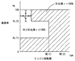
図6および図7を参照して、エンジン10の運転状態に対応させた情報である、筒内噴射用インジェクタ110と吸気通路噴射用インジェクタ120との噴き分け比率(DI比率rとも記載する。)を表わすマップについて説明する。これらのマップは、エンジンECU300のROM320に記憶される。図6は、エンジン10の温間用マップであって、図7は、エンジン10の冷間用マップである。
Referring to FIGS. 6 and 7, the injection ratio of in-
図6および図7に示すように、これらのマップは、エンジン10の回転数を横軸にして、負荷率を縦軸にして、筒内噴射用インジェクタ110の分担比率がDI比率rとして百分率で示されている。
As shown in FIG. 6 and FIG. 7, these maps are expressed in percentages where the
図6および図7に示すように、エンジン10の回転数と負荷率とに定まる運転領域ごとに、DI比率rが設定されている。「DI比率r=100%」とは、筒内噴射用インジェクタ110からのみ燃料噴射が行なわれる領域であることを意味し、「DI比率r=0%」とは、吸気通路噴射用インジェクタ120からのみ燃料噴射が行なわれる領域であることを意味する。「DI比率r≠0%」、「DI比率r≠100%」および「0%<DI比率r<100%」とは、筒内噴射用インジェクタ110と吸気通路噴射用インジェクタ120とで燃料噴射が分担して行なわれる領域であることを意味する。なお、概略的には、筒内噴射用インジェクタ110は、出力性能の上昇に寄与し、吸気通路噴射用インジェクタ120は、混合気の均一性に寄与する。このような特性の異なる2種類のインジェクタを、エンジン10の回転数と負荷率とで使い分けることにより、エンジン10が通常運転状態(たとえば、アイドル時の触媒暖気時が、通常運転状態以外の非通常運転状態の一例であるといえる)である場合には、均質燃焼のみが行なわれるようにしている。
As shown in FIGS. 6 and 7, the DI ratio r is set for each operation region determined by the rotational speed and load factor of the
さらに、これらの図6および図7に示すように、温間時のマップと冷間時のマップとに分けて、筒内噴射用インジェクタ110と吸気通路噴射用インジェクタ120のDI分担率rを規定した。エンジン10の温度が異なると、筒内噴射用インジェクタ110および吸気通路噴射用インジェクタ120の制御領域が異なるように設定されたマップを用いて、エンジン10の温度を検知して、エンジン10の温度が予め定められた温度しきい値以上であると図6の温間時のマップを選択して、そうではないと図7に示す冷間時のマップを選択する。それぞれ選択されたマップに基づいて、エンジン10の回転数と負荷率とに基づいて、筒内噴射用インジェクタ110および/または吸気通路噴射用インジェクタ120を制御する。
Further, as shown in FIG. 6 and FIG. 7, the DI share ratio r of the in-
図6および図7に設定されるエンジン10の回転数と負荷率について説明する。図6のNE(1)は2500〜2700rpmに設定され、KL(1)は30〜50%、KL(2)は60〜90%に設定されている。また、図7のNE(3)は2900〜3100rpmに設定されている。すなわち、NE(1)<NE(3)である。その他、図6のNE(2)や、図7のKL(3)、KL(4)も適宜設定されている。
The engine speed and load factor of
図6および図7を比較すると、図6に示す温間用マップのNE(1)よりも図7に示す冷間用マップのNE(3)の方が高い。これは、エンジン10の温度が低いほど、吸気通路噴射用インジェクタ120の制御領域が高いエンジン回転数の領域まで拡大されるということを示す。すなわち、エンジン10が冷えている状態であるので、(たとえ、筒内噴射用インジェクタ110から燃料を噴射しなくても)筒内噴射用インジェクタ110の噴口にデポジットが堆積しにくい。このため、吸気通路噴射用インジェクタ120を使って燃料を噴射する領域を拡大するように設定され、均質性を向上させることができる。
Comparing FIG. 6 and FIG. 7, NE (3) of the cold map shown in FIG. 7 is higher than NE (1) of the warm map shown in FIG. This indicates that as the temperature of the
図6および図7を比較すると、エンジン10の回転数が、温間用マップにおいてはNE(1)以上の領域において、冷間用マップにおいてはNE(3)以上の領域において、「DI比率r=100%」である。また、負荷率が、温間用マップにおいてはKL(2)以上の領域において、冷間用マップにおいてはKL(4)以上の領域において、「DI比率r=100%」である。これは、予め定められた高エンジン回転数領域では筒内噴射用インジェクタ110のみが使用されること、予め定められた高エンジン負荷領域では筒内噴射用インジェクタ110のみが使用されるということを示す。すなわち、高回転領域や高負荷領域においては、筒内噴射用インジェクタ110のみで燃料を噴射しても、エンジン10の回転数や負荷が高く吸気量が多いので筒内噴射用インジェクタ110のみでも混合気を均質化しやすいためである。このようにすると、筒内噴射用インジェクタ110から噴射された燃料は燃焼室内で気化潜熱を伴い(燃焼室から熱を奪い)気化される。これにより、圧縮端での混合気の温度が下がる。これにより対ノッキング性能が向上する。また、燃焼室の温度が下がるので、吸入効率が向上し高出力が見込める。
Comparing FIG. 6 and FIG. 7, “DI ratio r” in the region where the rotational speed of the
図6に示す温間マップでは、負荷率KL(1)以下では、筒内噴射用インジェクタ110のみが用いられる。これは、エンジン10の温度が高いときであって、予め定められた低負荷領域では筒内噴射用インジェクタ110のみが使用されるということを示す。これは、温間時においてはエンジン10が暖まった状態であるので、筒内噴射用インジェクタ110の噴口にデポジットが堆積しやすい。しかしながら、筒内噴射用インジェクタ110を使って燃料を噴射することにより噴口温度を低下させることができるので、デポジットの堆積を回避することも考えられ、また、筒内噴射用インジェクタの最小燃料噴射量を確保して、筒内噴射用インジェクタ110を閉塞させないことも考えられ、このために、筒内噴射用インジェクタ110を用いた領域としている。
In the warm map shown in FIG. 6, only the in-
図6および図7を比較すると、図7の冷間用マップにのみ「DI比率r=0%」の領域が存在する。これは、エンジン10の温度が低いときであって、予め定められた低負荷領域(KL(3)以下)では吸気通路噴射用インジェクタ120のみが使用されるということを示す。これはエンジン10が冷えていてエンジン10の負荷が低く吸気量も低いため燃料が霧化しにくい。このような領域においては筒内噴射用インジェクタ110による燃料噴射では良好な燃焼が困難であるため、また、特に低負荷および低回転数の領域では筒内噴射用インジェクタ110を用いた高出力を必要としないため、筒内噴射用インジェクタ110を用いないで、吸気通路噴射用インジェクタ120のみを用いる。
Comparing FIG. 6 and FIG. 7, an area of “DI ratio r = 0%” exists only in the cold map of FIG. 7. This indicates that when the temperature of the
また、通常運転時以外の場合、エンジン10がアイドル時の触媒暖気時の場合(非通常運転状態であるとき)、成層燃焼を行なうように筒内噴射用インジェクタ110が制御される。このような触媒暖気運転中にのみ成層燃焼させることで、触媒暖気を促進させ、排気エミッションの向上を図る。
In addition, in the case other than the normal operation, the in-
<この制御装置が適用されるに適したエンジン(その2)>
以下、本実施の形態に係る制御装置が適用されるに適したエンジン(その2)について説明する。なお、以下のエンジン(その2)の説明において、エンジン(その1)と同じ説明については、ここでは繰り返さない。
<Engine suitable for application of this control device (part 2)>
Hereinafter, an engine (part 2) suitable for application of the control device according to the present embodiment will be described. In the following description of the engine (part 2), the same description as the engine (part 1) will not be repeated here.
図8および図9を参照して、エンジン10の運転状態に対応させた情報である、筒内噴射用インジェクタ110と吸気通路噴射用インジェクタ120との噴き分け比率を表わすマップについて説明する。これらのマップは、エンジンECU300のROM320に記憶される。図8は、エンジン10の温間用マップであって、図9は、エンジン10の冷間用マップである。
With reference to FIGS. 8 and 9, a map representing the injection ratio of in-
図8および図9を比較すると、以下の点で図6および図7と異なる。エンジン10の回転数が、温間用マップにおいてはNE(1)以上の領域において、冷間用マップにおいてはNE(3)以上の領域において、「DI比率r=100%」である。また、負荷率が、温間用マップにおいては低回転数領域を除くKL(2)以上の領域において、冷間用マップにおいては低回転数領域を除くKL(4)以上の領域において、「DI比率r=100%」である。これは、予め定められた高エンジン回転数領域では筒内噴射用インジェクタ110のみが使用されること、予め定められた高エンジン負荷領域では筒内噴射用インジェクタ110のみが使用される領域が多いことを示す。しかしながら、低回転数領域の高負荷領域においては、筒内噴射用インジェクタ110から噴射された燃料により形成される混合気のミキシングが良好ではなく、燃焼室内の混合気が不均質で燃焼が不安定になる傾向を有する。このため、このような問題が発生しない高回転数領域へ移行するに伴い筒内噴射用インジェクタの噴射比率を増大させるようにしている。また、このような問題が発生する高負荷領域へ移行するに伴い筒内噴射用インジェクタ110の噴射比率を減少させるようにしている。これらのDI比率rの変化を図8および図9に十字の矢印で示す。このようにすると、燃焼が不安定であることに起因するエンジンの出力トルクの変動を抑制することができる。なお、これらのことは、予め定められた低回転数領域へ移行するに伴い筒内噴射用インジェクタ110の噴射比率を減少させることや、予め定められた低負荷領域へ移行するに伴い筒内噴射用インジェクタ110の噴射比率を増大させることと、略等価であることを確認的に記載する。また、このような領域(図8および図9で十字の矢印が記載された領域)以外の領域であって筒内噴射用インジェクタ110のみで燃料を噴射している領域(高回転側、低負荷側)においては、筒内噴射用インジェクタ110のみでも混合気を均質化しやすい。このようにすると、筒内噴射用インジェクタ110から噴射された燃料は燃焼室内で気化潜熱を伴い(燃焼室から熱を奪い)気化される。これにより、圧縮端での混合気の温度が下がる。これにより対ノッキング性能が向上する。また、燃焼室の温度が下がるので、吸入効率が向上し高出力が見込める。
8 and 9 differ from FIGS. 6 and 7 in the following points. The rotational speed of the
なお、図6〜図9を用いて説明したこのエンジン10においては、均質燃焼は筒内噴射用インジェクタ110の燃料噴射タイミングを吸気行程とすることにより、成層燃焼は筒内噴射用インジェクタ110の燃料噴射タイミングを圧縮行程とすることにより実現できる。すなわち、筒内噴射用インジェクタ110の燃料噴射タイミングを圧縮行程とすることで、点火プラグ周りにリッチ混合気が偏在させることにより燃焼室全体としてはリーンな混合気に着火する成層燃焼を実現することができる。また、筒内噴射用インジェクタ110の燃料噴射タイミングを吸気行程としても点火プラグ周りにリッチ混合気を偏在させることができれば、吸気行程噴射であっても成層燃焼を実現できる。
In the
また、ここでいう成層燃焼には、成層燃焼と以下に示す弱成層燃焼の双方を含むものである。弱成層燃焼とは、吸気通路噴射用インジェクタ120を吸気行程で燃料噴射して燃焼室全体にリーンで均質な混合気を生成して、さらに筒内噴射用インジェクタ110を圧縮行程で燃料噴射して点火プラグ周りにリッチな混合気を生成して、燃焼状態の向上を図るものである。このような弱成層燃焼は触媒暖気時に好ましい。これは、以下の理由による。すなわち、触媒暖気時には高温の燃焼ガスを触媒に到達させるために点火時期を大幅に遅角させ、かつ良好な燃焼状態(アイドル状態)を維持する必要がある。また、ある程度の燃料量を供給する必要がある。これを成層燃焼で行なおうとしても燃料量が少ないという問題があり、これを均質燃焼で行なおうとしても良好な燃焼を維持するために遅角量が成層燃焼に比べて小さいという問題がある。このような観点から、上述した弱成層燃焼を触媒暖気時に用いることが好ましいが、成層燃焼および弱成層燃焼のいずれであっても構わない。
Further, the stratified combustion here includes both stratified combustion and weak stratified combustion described below. In the weak stratified combustion, the
また、図6〜図9を用いて説明したエンジンにおいては、筒内噴射用インジェクタ110による燃料噴射のタイミングは、以下のような理由により、圧縮行程で行なうことが好ましい。ただし、上述したエンジン10は、基本的な大部分の領域には(触媒暖気時にのみに行なわれる、吸気通路噴射用インジェクタ120を吸気行程噴射させ、筒内噴射用インジェクタ110を圧縮行程噴射させる弱成層燃焼領域以外を基本的な領域という)、筒内噴射用インジェクタ110による燃料噴射のタイミングは、吸気行程である。しかしながら、以下に示す理由があるので、燃焼安定化を目的として一時的に筒内噴射用インジェクタ110の燃料噴射タイミングを圧縮行程噴射とするようにしてもよい。
Further, in the engine described with reference to FIGS. 6 to 9, the fuel injection timing by the in-
筒内噴射用インジェクタ110からの燃料噴射時期を圧縮行程中とすることで、筒内温度がより高い時期において、燃料噴射により混合気が冷却される。冷却効果が高まるので、対ノック性を改善することができる。さらに、筒内噴射用インジェクタ110からの燃料噴射時期を圧縮行程中とすると、燃料噴射から点火時期までの時間が短いことから噴霧による気流の強化を実現でき、燃焼速度を上昇させることができる。これらの対ノック性の向上と燃焼速度の上昇とから、燃焼変動を回避して、燃焼安定性を向上させることができる。
By setting the fuel injection timing from the in-
<変形例>
上述した第1の実施の形態と第2の実施の形態とを組み合わせてもよい。すなわちVVT装置とPCV装置とを備え、筒内噴射用インジェクタ110と吸気通路噴射用インジェクタ120とで燃料噴射を分担するエンジンにおいて、VVT装置による吸排気バルブのオーバラップ量がしきい値以上であって、かつ、PCVブローバイガスに含まれるオイル成分がしきい値以上であると、DI比率rが1であっても、吸気通路噴射用インジェクタ120から燃料を噴射するようにエンジンECU300により制御する。
<Modification>
You may combine 1st Embodiment mentioned above and 2nd Embodiment. That is, in an engine equipped with a VVT device and a PCV device and sharing fuel injection between the in-
なお、上述した実施の形態においては、吸気通路噴射用インジェクタ120がインテークマニホールド20の上流側へ向けて燃料を噴射する構成としたが、吸気通路噴射用インジェクタ120がインテークマニホールド20の下流側(燃焼室側)へ向けて燃料を噴射する構成としてもよい。また、フローチャートにおけるS110の処理については、DI比率rが1未満であって、吸気通路噴射用インジェクタ120から微小量の燃料が噴射されている場合でも、S120以降の処理またはS220以降の処理を行なうようにしてもよい。
In the above-described embodiment, the
今回開示された実施の形態はすべての点で例示であって制限的なものではないと考えられるべきである。本発明の範囲は上記した説明ではなくて特許請求の範囲によって示され、特許請求の範囲と均等の意味および範囲内でのすべての変更が含まれることが意図される。 The embodiment disclosed this time should be considered as illustrative in all points and not restrictive. The scope of the present invention is defined by the terms of the claims, rather than the description above, and is intended to include any modifications within the scope and meaning equivalent to the terms of the claims.
10 エンジン、20 インテークマニホールド、30 サージタンク、40 吸気ダクト、42 エアフローメータ、50 エアクリーナ、60 電動モータ、70 スロットルバルブ、80 エキゾーストマニホールド、90 三元触媒コンバータ、100 アクセルペダル、102 クランクケース、104 シリンダ、110 筒内噴射用インジェクタ、112 気筒、116 シリンダヘッド、119 点火プラグ、120 吸気通路噴射用インジェクタ、121 排気バルブ、122 吸気バルブ、123 ピストン、130 燃料分配管、140 逆止弁、150 高圧燃料ポンプ、152 電磁スピル弁、160 燃料分配管(低圧側)、170 燃料圧レギュレータ、180 低圧燃料ポンプ、190 燃料フィルタ、200 燃料タンク、300 エンジンECU、310 双方向性バス、320 ROM、330 RAM、340 CPU、350 入力ポート、360 出力ポート、370,390,410,430,450 A/D変換器、380 水温センサ、400 燃料圧センサ、420 空燃比センサ、440 アクセル開度センサ、460 回転数センサ。
10 engine, 20 intake manifold, 30 surge tank, 40 air intake duct, 42 air flow meter, 50 air cleaner, 60 electric motor, 70 throttle valve, 80 exhaust manifold, 90 three-way catalytic converter, 100 accelerator pedal, 102 crankcase, 104 cylinder , 110 In-cylinder injector, 112 cylinder, 116 cylinder head, 119 Spark plug, 120 Intake passage injector, 121 Exhaust valve, 122 Intake valve, 123 piston, 130 Fuel distribution pipe, 140 Check valve, 150 High pressure fuel Pump, 152 Electromagnetic spill valve, 160 Fuel distribution pipe (low pressure side), 170 Fuel pressure regulator, 180 Low pressure fuel pump, 190 Fuel filter, 200 Fuel tank, 3 0 engine ECU, 310 bidirectional bus, 320 ROM, 330 RAM, 340 CPU, 350 input port, 360 output port, 370, 390, 410, 430, 450 A / D converter, 380 water temperature sensor, 400
Claims (9)
前記第1の燃料噴射手段および前記第2の燃料噴射手段の一方の噴射停止を含んで、燃料を分担して噴射するように、燃料噴射手段を制御するための噴射制御手段と、
還流されるブローバイガスの状態に基づいて、前記第2の燃料噴射手段から噴射される燃料量を変更するための制御手段とを含み、
前記制御手段は、前記噴射制御手段が前記第2の燃料噴射手段の噴射を停止させているときに、前記第2の燃料噴射手段から燃料を噴射するための手段を含む、内燃機関の制御装置。 A first fuel injection means for injecting fuel into the cylinder and a second fuel injection means for injecting fuel into the intake passage, wherein the blow-by gas is upstream of the second fuel injection means A control device for an internal combustion engine that is recirculated into the intake passage of the engine,
Injection control means for controlling the fuel injection means so as to share and inject fuel, including stopping injection of one of the first fuel injection means and the second fuel injection means;
Control means for changing the amount of fuel injected from the second fuel injection means based on the state of the blow-by gas to be recirculated ,
The control device of the internal combustion engine, wherein the control means includes means for injecting fuel from the second fuel injection means when the injection control means stops the injection of the second fuel injection means .
、前記第1の燃料噴射手段を制御するための手段を含む、請求項1〜5のいずれかに記載の内燃機関の制御装置。 The injection control means reduces the amount of fuel injected by the second fuel injection means by the control means from the fuel injected from the first fuel injection means and injects the fuel. The control apparatus for an internal combustion engine according to any one of claims 1 to 5 , further comprising means for controlling one fuel injection means.
前記第2の燃料噴射手段は、吸気通路用インジェクタである、請求項1〜8のいずれかに記載の内燃機関の制御装置。 The first fuel injection means is an in-cylinder injector,
It said second fuel injection means is an intake manifold injector, the control apparatus for an internal combustion engine according to any one of claims 1-8.
Priority Applications (1)
| Application Number | Priority Date | Filing Date | Title |
|---|---|---|---|
| JP2005039541A JP4591107B2 (en) | 2005-02-16 | 2005-02-16 | Control device for internal combustion engine |
Applications Claiming Priority (1)
| Application Number | Priority Date | Filing Date | Title |
|---|---|---|---|
| JP2005039541A JP4591107B2 (en) | 2005-02-16 | 2005-02-16 | Control device for internal combustion engine |
Publications (2)
| Publication Number | Publication Date |
|---|---|
| JP2006226163A JP2006226163A (en) | 2006-08-31 |
| JP4591107B2 true JP4591107B2 (en) | 2010-12-01 |
Family
ID=36987746
Family Applications (1)
| Application Number | Title | Priority Date | Filing Date |
|---|---|---|---|
| JP2005039541A Expired - Fee Related JP4591107B2 (en) | 2005-02-16 | 2005-02-16 | Control device for internal combustion engine |
Country Status (1)
| Country | Link |
|---|---|
| JP (1) | JP4591107B2 (en) |
Families Citing this family (9)
| Publication number | Priority date | Publication date | Assignee | Title |
|---|---|---|---|---|
| JP4835579B2 (en) * | 2007-11-12 | 2011-12-14 | トヨタ自動車株式会社 | Control device for internal combustion engine |
| JP5195251B2 (en) * | 2008-10-03 | 2013-05-08 | トヨタ自動車株式会社 | Internal combustion engine control system |
| JP5321354B2 (en) * | 2008-10-20 | 2013-10-23 | トヨタ自動車株式会社 | Fuel injection device |
| EP2415997B1 (en) * | 2009-04-02 | 2015-10-07 | Toyota Jidosha Kabushiki Kaisha | Control system of an internal combustion engine |
| US20130174811A1 (en) * | 2011-04-20 | 2013-07-11 | Toyota Jidosha Kabushiki Kaisha | Fuel supply device for internal combustion engine |
| JP5737262B2 (en) | 2012-10-16 | 2015-06-17 | トヨタ自動車株式会社 | Control device for internal combustion engine |
| JP2014222024A (en) * | 2013-05-13 | 2014-11-27 | トヨタ自動車株式会社 | Internal combustion engine |
| JP7841419B2 (en) * | 2022-12-20 | 2026-04-07 | トヨタ自動車株式会社 | Internal combustion engine |
| CN118855603B (en) * | 2024-09-29 | 2025-01-14 | 张家港长城汽车研发有限公司 | Engine control method and device, engine management system and hybrid vehicle |
Family Cites Families (16)
| Publication number | Priority date | Publication date | Assignee | Title |
|---|---|---|---|---|
| JP3523278B2 (en) * | 1992-08-28 | 2004-04-26 | トヨタ自動車株式会社 | Combustion chamber of internal combustion engine |
| JPH06147061A (en) * | 1992-11-11 | 1994-05-27 | Nippondenso Co Ltd | Fuel injection system of internal combustion engine |
| JP3629879B2 (en) * | 1997-03-13 | 2005-03-16 | トヨタ自動車株式会社 | Compression ignition internal combustion engine |
| JP3398567B2 (en) * | 1997-06-06 | 2003-04-21 | 株式会社日本自動車部品総合研究所 | In-cylinder direct injection internal combustion engine with variable valve timing means |
| JP3395643B2 (en) * | 1998-04-08 | 2003-04-14 | 日産自動車株式会社 | Fuel injection device for internal combustion engine |
| JPH11351041A (en) * | 1998-06-08 | 1999-12-21 | Fuji Heavy Ind Ltd | Fuel injection type internal-combustion engine |
| JP2000186601A (en) * | 1998-12-24 | 2000-07-04 | Mazda Motor Corp | Control unit for diesel engine |
| JP2001271686A (en) * | 2000-03-28 | 2001-10-05 | Fuji Heavy Ind Ltd | Fuel injection control device for in-cylinder fuel injection engine |
| JP2002276402A (en) * | 2001-03-19 | 2002-09-25 | Toyota Motor Corp | Fuel injection control device for in-cylinder internal combustion engine |
| DE10141959A1 (en) * | 2001-08-28 | 2003-04-10 | Bosch Gmbh Robert | Fuel injection system for internal combustion engines with gasoline direct injection with optimal injection into the intake pipe and method for their operation |
| JP2003138966A (en) * | 2001-11-01 | 2003-05-14 | Fuji Heavy Ind Ltd | Engine control device |
| JP4145098B2 (en) * | 2002-08-22 | 2008-09-03 | 株式会社日本自動車部品総合研究所 | Variable compression ratio engine and its control |
| JP2004308618A (en) * | 2003-04-10 | 2004-11-04 | Toyota Motor Corp | Internal combustion engine having compression ratio changing mechanism and control method for internal combustion engine |
| JP2004353476A (en) * | 2003-05-27 | 2004-12-16 | Toyota Motor Corp | Control device for internal combustion engine |
| JP4163995B2 (en) * | 2003-05-30 | 2008-10-08 | ヤンマー株式会社 | Monitoring and diagnosis system |
| JP4447473B2 (en) * | 2005-01-13 | 2010-04-07 | 株式会社日本自動車部品総合研究所 | Control device for internal combustion engine |
-
2005
- 2005-02-16 JP JP2005039541A patent/JP4591107B2/en not_active Expired - Fee Related
Also Published As
| Publication number | Publication date |
|---|---|
| JP2006226163A (en) | 2006-08-31 |
Similar Documents
| Publication | Publication Date | Title |
|---|---|---|
| JP4661979B2 (en) | Control device for internal combustion engine | |
| JP4375201B2 (en) | Control device for internal combustion engine | |
| JP4433920B2 (en) | Control device for internal combustion engine | |
| JP4595952B2 (en) | Control device for internal combustion engine, control method, program for realizing the method, and recording medium recording the program | |
| JP4356595B2 (en) | Control device for internal combustion engine | |
| JP4449706B2 (en) | Control device for internal combustion engine | |
| JP4453625B2 (en) | Control device for internal combustion engine | |
| CN101287900A (en) | Internal Combustion Engine Controls | |
| JP4453524B2 (en) | Control device for internal combustion engine | |
| JP4506526B2 (en) | Control device for internal combustion engine | |
| CN102084109B (en) | Control device for vehicle | |
| JP2006258007A (en) | Control device for internal combustion engine | |
| JP2006258021A (en) | Control device for internal combustion engine | |
| JP4591107B2 (en) | Control device for internal combustion engine | |
| US7357122B2 (en) | Internal combustion engine control apparatus | |
| JP2006132396A (en) | Control device for internal combustion engine | |
| JP2006258023A (en) | Control device for internal combustion engine | |
| JP2012087641A (en) | Fuel injection device | |
| JP4701897B2 (en) | Control device for internal combustion engine | |
| JP2006063947A (en) | Control device for internal combustion engine | |
| JP2006183534A (en) | Control device for internal combustion engine | |
| JP2006336620A (en) | Fuel injection control device for internal combustion engine | |
| JP2006291876A (en) | Control device for internal combustion engine | |
| JP2007032298A (en) | Spark ignition internal combustion engine | |
| JPH11351013A (en) | Fuel injection control device for internal combustion engine |
Legal Events
| Date | Code | Title | Description |
|---|---|---|---|
| A621 | Written request for application examination |
Free format text: JAPANESE INTERMEDIATE CODE: A621 Effective date: 20080130 |
|
| A977 | Report on retrieval |
Free format text: JAPANESE INTERMEDIATE CODE: A971007 Effective date: 20091001 |
|
| A131 | Notification of reasons for refusal |
Free format text: JAPANESE INTERMEDIATE CODE: A131 Effective date: 20091222 |
|
| A521 | Request for written amendment filed |
Free format text: JAPANESE INTERMEDIATE CODE: A523 Effective date: 20100215 |
|
| A131 | Notification of reasons for refusal |
Free format text: JAPANESE INTERMEDIATE CODE: A131 Effective date: 20100323 |
|
| A521 | Request for written amendment filed |
Free format text: JAPANESE INTERMEDIATE CODE: A523 Effective date: 20100514 |
|
| TRDD | Decision of grant or rejection written | ||
| A01 | Written decision to grant a patent or to grant a registration (utility model) |
Free format text: JAPANESE INTERMEDIATE CODE: A01 Effective date: 20100817 |
|
| A01 | Written decision to grant a patent or to grant a registration (utility model) |
Free format text: JAPANESE INTERMEDIATE CODE: A01 |
|
| A61 | First payment of annual fees (during grant procedure) |
Free format text: JAPANESE INTERMEDIATE CODE: A61 Effective date: 20100830 |
|
| FPAY | Renewal fee payment (event date is renewal date of database) |
Free format text: PAYMENT UNTIL: 20130924 Year of fee payment: 3 |
|
| R151 | Written notification of patent or utility model registration |
Ref document number: 4591107 Country of ref document: JP Free format text: JAPANESE INTERMEDIATE CODE: R151 |
|
| FPAY | Renewal fee payment (event date is renewal date of database) |
Free format text: PAYMENT UNTIL: 20130924 Year of fee payment: 3 |
|
| LAPS | Cancellation because of no payment of annual fees |