JP4599397B2 - Pump unit, syringe unit, particle delivery method, and cell delivery method - Google Patents
Pump unit, syringe unit, particle delivery method, and cell delivery method Download PDFInfo
- Publication number
- JP4599397B2 JP4599397B2 JP2007506956A JP2007506956A JP4599397B2 JP 4599397 B2 JP4599397 B2 JP 4599397B2 JP 2007506956 A JP2007506956 A JP 2007506956A JP 2007506956 A JP2007506956 A JP 2007506956A JP 4599397 B2 JP4599397 B2 JP 4599397B2
- Authority
- JP
- Japan
- Prior art keywords
- tip
- relationship
- syringe
- pump
- storage tank
- Prior art date
- Legal status (The legal status is an assumption and is not a legal conclusion. Google has not performed a legal analysis and makes no representation as to the accuracy of the status listed.)
- Expired - Fee Related
Links
Images






Classifications
-
- B—PERFORMING OPERATIONS; TRANSPORTING
- B01—PHYSICAL OR CHEMICAL PROCESSES OR APPARATUS IN GENERAL
- B01L—CHEMICAL OR PHYSICAL LABORATORY APPARATUS FOR GENERAL USE
- B01L3/00—Containers or dishes for laboratory use, e.g. laboratory glassware; Droppers
- B01L3/50—Containers for the purpose of retaining a material to be analysed, e.g. test tubes
- B01L3/502—Containers for the purpose of retaining a material to be analysed, e.g. test tubes with fluid transport, e.g. in multi-compartment structures
- B01L3/5027—Containers for the purpose of retaining a material to be analysed, e.g. test tubes with fluid transport, e.g. in multi-compartment structures by integrated microfluidic structures, i.e. dimensions of channels and chambers are such that surface tension forces are important, e.g. lab-on-a-chip
- B01L3/502715—Containers for the purpose of retaining a material to be analysed, e.g. test tubes with fluid transport, e.g. in multi-compartment structures by integrated microfluidic structures, i.e. dimensions of channels and chambers are such that surface tension forces are important, e.g. lab-on-a-chip characterised by interfacing components, e.g. fluidic, electrical, optical or mechanical interfaces
-
- B—PERFORMING OPERATIONS; TRANSPORTING
- B01—PHYSICAL OR CHEMICAL PROCESSES OR APPARATUS IN GENERAL
- B01L—CHEMICAL OR PHYSICAL LABORATORY APPARATUS FOR GENERAL USE
- B01L3/00—Containers or dishes for laboratory use, e.g. laboratory glassware; Droppers
- B01L3/02—Burettes; Pipettes
- B01L3/0289—Apparatus for withdrawing or distributing predetermined quantities of fluid
-
- C—CHEMISTRY; METALLURGY
- C12—BIOCHEMISTRY; BEER; SPIRITS; WINE; VINEGAR; MICROBIOLOGY; ENZYMOLOGY; MUTATION OR GENETIC ENGINEERING
- C12M—APPARATUS FOR ENZYMOLOGY OR MICROBIOLOGY; APPARATUS FOR CULTURING MICROORGANISMS FOR PRODUCING BIOMASS, FOR GROWING CELLS OR FOR OBTAINING FERMENTATION OR METABOLIC PRODUCTS, i.e. BIOREACTORS OR FERMENTERS
- C12M33/00—Means for introduction, transport, positioning, extraction, harvesting, peeling or sampling of biological material in or from the apparatus
- C12M33/04—Means for introduction, transport, positioning, extraction, harvesting, peeling or sampling of biological material in or from the apparatus by injection or suction, e.g. using pipettes, syringes, needles
-
- B—PERFORMING OPERATIONS; TRANSPORTING
- B01—PHYSICAL OR CHEMICAL PROCESSES OR APPARATUS IN GENERAL
- B01L—CHEMICAL OR PHYSICAL LABORATORY APPARATUS FOR GENERAL USE
- B01L2200/00—Solutions for specific problems relating to chemical or physical laboratory apparatus
- B01L2200/02—Adapting objects or devices to another
- B01L2200/026—Fluid interfacing between devices or objects, e.g. connectors, inlet details
- B01L2200/027—Fluid interfacing between devices or objects, e.g. connectors, inlet details for microfluidic devices
-
- B—PERFORMING OPERATIONS; TRANSPORTING
- B01—PHYSICAL OR CHEMICAL PROCESSES OR APPARATUS IN GENERAL
- B01L—CHEMICAL OR PHYSICAL LABORATORY APPARATUS FOR GENERAL USE
- B01L2200/00—Solutions for specific problems relating to chemical or physical laboratory apparatus
- B01L2200/06—Fluid handling related problems
- B01L2200/0605—Metering of fluids
-
- B—PERFORMING OPERATIONS; TRANSPORTING
- B01—PHYSICAL OR CHEMICAL PROCESSES OR APPARATUS IN GENERAL
- B01L—CHEMICAL OR PHYSICAL LABORATORY APPARATUS FOR GENERAL USE
- B01L2200/00—Solutions for specific problems relating to chemical or physical laboratory apparatus
- B01L2200/06—Fluid handling related problems
- B01L2200/0647—Handling flowable solids, e.g. microscopic beads, cells, particles
-
- B—PERFORMING OPERATIONS; TRANSPORTING
- B01—PHYSICAL OR CHEMICAL PROCESSES OR APPARATUS IN GENERAL
- B01L—CHEMICAL OR PHYSICAL LABORATORY APPARATUS FOR GENERAL USE
- B01L2300/00—Additional constructional details
- B01L2300/08—Geometry, shape and general structure
- B01L2300/0861—Configuration of multiple channels and/or chambers in a single devices
-
- B—PERFORMING OPERATIONS; TRANSPORTING
- B01—PHYSICAL OR CHEMICAL PROCESSES OR APPARATUS IN GENERAL
- B01L—CHEMICAL OR PHYSICAL LABORATORY APPARATUS FOR GENERAL USE
- B01L2300/00—Additional constructional details
- B01L2300/08—Geometry, shape and general structure
- B01L2300/0861—Configuration of multiple channels and/or chambers in a single devices
- B01L2300/0877—Flow chambers
-
- B—PERFORMING OPERATIONS; TRANSPORTING
- B01—PHYSICAL OR CHEMICAL PROCESSES OR APPARATUS IN GENERAL
- B01L—CHEMICAL OR PHYSICAL LABORATORY APPARATUS FOR GENERAL USE
- B01L2400/00—Moving or stopping fluids
- B01L2400/04—Moving fluids with specific forces or mechanical means
- B01L2400/0475—Moving fluids with specific forces or mechanical means specific mechanical means and fluid pressure
- B01L2400/0478—Moving fluids with specific forces or mechanical means specific mechanical means and fluid pressure pistons
-
- B—PERFORMING OPERATIONS; TRANSPORTING
- B01—PHYSICAL OR CHEMICAL PROCESSES OR APPARATUS IN GENERAL
- B01L—CHEMICAL OR PHYSICAL LABORATORY APPARATUS FOR GENERAL USE
- B01L3/00—Containers or dishes for laboratory use, e.g. laboratory glassware; Droppers
- B01L3/02—Burettes; Pipettes
- B01L3/021—Pipettes, i.e. with only one conduit for withdrawing and redistributing liquids
- B01L3/0217—Pipettes, i.e. with only one conduit for withdrawing and redistributing liquids of the plunger pump type
Landscapes
- Chemical & Material Sciences (AREA)
- Health & Medical Sciences (AREA)
- Life Sciences & Earth Sciences (AREA)
- Analytical Chemistry (AREA)
- Clinical Laboratory Science (AREA)
- Chemical Kinetics & Catalysis (AREA)
- Organic Chemistry (AREA)
- General Health & Medical Sciences (AREA)
- Zoology (AREA)
- Wood Science & Technology (AREA)
- Engineering & Computer Science (AREA)
- Bioinformatics & Cheminformatics (AREA)
- Biomedical Technology (AREA)
- Biotechnology (AREA)
- Microbiology (AREA)
- Sustainable Development (AREA)
- Molecular Biology (AREA)
- Hematology (AREA)
- Biochemistry (AREA)
- General Engineering & Computer Science (AREA)
- Genetics & Genomics (AREA)
- Dispersion Chemistry (AREA)
- Apparatus Associated With Microorganisms And Enzymes (AREA)
- Micro-Organisms Or Cultivation Processes Thereof (AREA)
Description
本発明は、粒子が分散した液体中の該粒子を所定の場所に送り込むポンプユニット、およびそのポンプユニットを用いて実施する粒子送出方法、並びに細胞が分散した懸濁液中の該細胞をマイクロチャネルに送り込むシリンジユニット、およびそのシリンジユニットを用いて実施する細胞送出方法に関する。 The present invention relates to a pump unit that feeds particles in a liquid in which particles are dispersed to a predetermined place, a particle delivery method that is performed using the pump unit, and a microchannel for the cells in a suspension in which cells are dispersed. The present invention relates to a syringe unit that is fed into a cell and a cell delivery method that is performed using the syringe unit.
液体中に混合・拡散させた粒子を移送するシステムとして様々な装置が提案されている(例えば、特許文献1及び2等参照)が、ここでは、医学分野における血球由来細胞や幹細胞への物質導入装置に用いられるシリンジユニット(例えば、特許文献3等参照)を例にあげて説明する。特許文献3には、大量に連続処理を行うための物質導入装置が示されており、この物質導入装置に配備されたシリンジユニットは、シリンジ(注射器)を用いて細胞を微小な溝(マイクロチャネル)に送り込むものである。
Various apparatuses have been proposed as a system for transferring particles mixed and diffused in a liquid (see, for example, Patent Documents 1 and 2). Here, substances are introduced into blood cells and stem cells in the medical field. A syringe unit (see, for example, Patent Document 3) used in the apparatus will be described as an example.
一般に、血球由来細胞や幹細胞への物質導入にあたっては、まず、導入対象である血球由来細胞や幹細胞を生体から取り出し、トリプシンなどの分散化処理を行い、これらの細胞を培養液中に分散させる。次いで、培養液中に分散・浮遊化させた細胞をシリンジによってマイクロチャネルに送り込み、培養液を媒介とした流動により細胞を所定の処理位置まで移送する。処理位置に到達した細胞は、吸引機構により捕捉され、注入システムにより薬剤等が細胞の任意部位に導入される。 In general, when introducing a substance into blood cell-derived cells or stem cells, first, the blood cell-derived cells or stem cells to be introduced are taken out from the living body, subjected to a dispersion treatment such as trypsin, and these cells are dispersed in a culture solution. Next, the cells dispersed and suspended in the culture solution are sent to the microchannel by a syringe, and the cells are transferred to a predetermined processing position by a flow mediated by the culture solution. The cells that have reached the treatment position are captured by the suction mechanism, and a drug or the like is introduced into an arbitrary part of the cells by the injection system.
特許文献3に記載されたシリンジユニットは、内部に培養液が充填されたシリンジの先端とマイクロチャネルとをチューブで結び、シリンジの吐出動作を行うことで、細胞がチューブを通ってマイクロチャネルに送り込まれる。ここで、培養液で満たされたマイクロチャネル内に気泡が混入していると、シリンジの吐出動作を行っても、混入した気泡が細胞の移送を妨げ、マイクロチャネル内での送液が不安定になる。マイクロチャネル内への気泡の混入は、様々な原因によって生じるが、特に、培養液を吐出し終わったシリンジを培養液が充填されたシリンジに交換するシリンジ交換の際に、チューブ内に入り込む空気が大きな原因になる。
The syringe unit described in
ところで、処理位置では細胞を吸引機構によって確実に捕捉するため、CCDカメラによる画像解析によって細胞の移動をモニタにしており、細胞の移動をモニタするには、非常に微量の送液分解能が必要になる。すなわち、血球由来細胞は、浮遊化状態で直径が5〜20μm程度の大きさであり、マイクロチャネルの断面の大きさが細胞を内包する最小の寸法であればあるほど、細胞の移送や捕捉が容易になる。このため、マイクロチャネルの断面形状を1辺が50μmのほぼ正方形にすると、十分な送液分解能を得るためには細胞を500μm/secで移送する必要が生じ、そのための流量は1.25nL/secになる。そこで、十分な送液分解能を得るために内径の細いシリンジを用いることが考えられる。
しかしながら、内径の細いシリンジを用いると、一回の吐出量が少なくなり、特許文献3に記載されたシリンジユニットでは、頻繁なシリンジ交換が必要になり、マイクロチャネル内に気泡が大量に混入してしまう恐れがある。
However, when a syringe with a thin inner diameter is used, the amount of discharge at one time is reduced, and the syringe unit described in
本発明は、上記事情に鑑み、気泡が混入することを抑えつつ十分な送液分解能を得ることができるポンプユニットおよびシリンジユニット、並びにそのポンプユニットを用いて実施する粒子送出方法およびそのシリンジユニットを用いて実施する細胞送出方法を提供することを目的とする。 In view of the above circumstances, the present invention provides a pump unit and a syringe unit capable of obtaining sufficient liquid feeding resolution while suppressing the mixing of bubbles, a particle delivery method implemented using the pump unit, and a syringe unit thereof. It aims at providing the cell delivery method implemented using.
上記目的を解決する本発明のポンプユニットは、粒子が分散した液体中のその粒子を所定の場所に送り込むポンプユニットにおいて、
上記液体を貯留し、底部に上記所定の場所につながる開口が設けられた貯留槽、
上記液体を先端から吸引する吸引動作と吸引した液体をその先端から吐出する吐出動作とを行うポンプ、および
上記ポンプと上記貯留槽とを相対的に移動させることで、上記ポンプの先端と上記開口の縁との位置関係を、そのポンプの先端が上記貯留槽に貯留された液体中で上記開口の縁から上方に離間した離間関係と、その先端がその開口の縁に押し付けられた押付関係との間で変化させる移動機構を備え、
上記ポンプは、上記位置関係が、上記離間関係にある状態で上記吸引動作を行い上記粒子を内部に取込み、上記押付関係にある状態で上記吐出動作を行い該粒子を送出するものであり、
上記移動機構が、上記位置関係を、上記離間関係と上記押付関係との間で変化させるにあたり、上記先端を上記貯留槽に貯留された液体中に漬け込んだまま変化させるものであることを特徴とする。The pump unit of the present invention that solves the above-mentioned object is a pump unit that feeds particles in a liquid in which particles are dispersed to a predetermined place.
A storage tank in which the liquid is stored and an opening connected to the predetermined place is provided at the bottom,
A pump that performs a suction operation for sucking the liquid from the tip and a discharge operation for discharging the sucked liquid from the tip; and by moving the pump and the storage tank relatively, the tip of the pump and the opening The relationship between the edge of the pump and the edge of the pump is spaced apart from the edge of the opening in the liquid stored in the storage tank, and the pressing relation of the tip pressed against the edge of the opening. With a moving mechanism that changes between
The pump performs the suction operation in a state where the positional relationship is in the separated relationship, takes the particles inside, performs the discharge operation in a state in the pressing relationship, and sends the particles.
When the moving mechanism changes the positional relationship between the separation relationship and the pressing relationship, the moving mechanism changes the tip while being immersed in the liquid stored in the storage tank. To do.
本発明のポンプユニットによれば、上記位置関係が上記離間関係と上記押付関係との間で変化する間、上記ポンプ先端が上記液体の液面から引き上げられることがなく、シリンジ交換も必要がないことから空気の入り込みが防止される。このため、気泡が混入することが抑えられる。また、十分な送液分解能を得るために内径の細いシリンジを用いても、シリンジ交換が不要であり空気の入り込みが防止されているため、吐出動作と吸引動作を繰り返しても気泡が混入するといった問題が生じない。したがって、本発明のポンプユニットは、気泡が混入することを抑えつつ十分な送液分解能を得ることができる。 According to the pump unit of the present invention, while the positional relationship changes between the separation relationship and the pressing relationship, the pump tip is not pulled up from the liquid surface, and there is no need to replace the syringe. Therefore, the entry of air is prevented. For this reason, it is suppressed that a bubble mixes. In addition, even if a syringe with a small inner diameter is used to obtain sufficient liquid feeding resolution, syringe replacement is unnecessary and air entry is prevented, so that bubbles are mixed even if the discharge operation and the suction operation are repeated. There is no problem. Therefore, the pump unit of the present invention can obtain a sufficient liquid feeding resolution while suppressing the mixing of bubbles.
また、本発明のポンプユニットにおいて、上記ポンプが、このポンプユニットから分離可能なものであることが好ましい。 In the pump unit of the present invention, it is preferable that the pump is separable from the pump unit.
こうすることで、連続した送り込みを終えた後に新品のポンプに交換することができる。また、ポンプの清掃等のメンテナンスの際に、作業が行いやすい。 By doing so, it is possible to replace the pump with a new one after the continuous feeding. Also, it is easy to perform work during maintenance such as cleaning the pump.
ここで、上記移動機構は、上記ポンプの先端を上記開口の縁に向けて付勢する付勢手段と、その付勢手段の付勢力に抗して上記ポンプの先端を上記開口の縁から離間させるカム機構とを備えたものであってもよいし、あるいは、
上記移動機構が、ピエゾアクチュエータであってもよい。Here, the moving mechanism includes an urging means for urging the tip of the pump toward the edge of the opening, and the tip of the pump is separated from the edge of the opening against the urging force of the urging means. Or a cam mechanism to be used, or
The moving mechanism may be a piezo actuator.
また、本発明のポンプユニットにおいて、上記位置関係が上記離間関係にある状態で上記ポンプの先端と上記開口の縁との間に存在する粒子あるいは気泡をその間から除去する除去手段を備えたことが好ましく、
上記除去手段が、上記ポンプの先端に流体を吹き付けるものであってもよい。The pump unit according to the present invention further includes a removing means for removing particles or bubbles existing between the tip of the pump and the edge of the opening in a state where the positional relationship is the separated relationship. Preferably
The removing means may spray fluid on the tip of the pump.
上記除去手段を備えたことで、上記位置関係が上記離間関係から上記押付関係に変化する際に、上記ポンプの先端と上記開口の縁の間に上記粒子を挟み込んでしまうことを防止することができる。また、上記貯留槽に貯留された液体中に溶け込んでいた空気が気泡になって表れることがあり、こうして表れた気泡を除去することで、気泡が混入することをより確実に抑えることができる。 By providing the removing means, it is possible to prevent the particles from being sandwiched between the tip of the pump and the edge of the opening when the positional relationship changes from the separated relationship to the pressing relationship. it can. In addition, air dissolved in the liquid stored in the storage tank may appear as bubbles, and by removing the bubbles thus appearing, it is possible to more reliably prevent bubbles from being mixed.
また、本発明のポンプユニットにおいて、上記ポンプは、上記位置関係が上記移動機構によって上記離間関係から上記押付関係へ変化している最中に上記吐出動作を開始し、上記先端と上記開口の縁との間に存在する粒子あるいは気泡をその間から除去するものである態様や、あるいは、
上記移動機構は、上記位置関係が上記離間関係にある状態で、上記ポンプと上記貯留槽とを相対的に水平方向に移動させるものであり、
上記貯留槽は、底部に上向きに植毛され、上記ポンプとこの貯留槽とが相対的に水平方向に移動することでそのポンプの先端に摺擦しその先端に付着した付着物を除去するブラシ部材を有するものである態様も好ましい。In the pump unit of the present invention, the pump starts the discharge operation while the positional relationship is being changed from the separation relationship to the pressing relationship by the moving mechanism, and the edge of the tip and the opening is A mode that removes particles or bubbles existing between the two, or
The moving mechanism moves the pump and the storage tank relatively in the horizontal direction in a state where the positional relationship is in the separated relationship,
The storage tank is planted in the upper part at the bottom, and the pump and the storage tank move in a horizontal direction so that the brush slides on the tip of the pump and removes adhering matter attached to the tip. The aspect which has is also preferable.
これらの態様によっても、上記粒子の挟み込みや、気泡が混入することをより確実に抑えることができる。 Also according to these aspects, it is possible to more reliably suppress the sandwiching of the particles and the mixing of bubbles.
さらに、本発明のポンプユニットにおいて、上記貯留槽は、上記開口の縁が、上記底部の、その縁を囲う部分よりも上方に突出したものであることも好ましく、さらには、
上記開口の縁は、突出先端面が上に凸の曲面であることがより好ましい。Furthermore, in the pump unit of the present invention, the storage tank preferably has an edge of the opening that protrudes upward from a portion of the bottom that surrounds the edge.
It is more preferable that the edge of the opening is a curved surface with a protruding tip surface protruding upward.
上記縁を突出させることで、上記ポンプ先端が接する上記縁の面積が小さくなり、上記ポンプ先端の接触圧が高められる。また、上記ポンプ先端と上記開口の縁との間に上記粒子を挟み込む可能性が低くなり、突出量が上記粒子の直径よりも大きければ、その可能性がより低くなる。さらに、上に凸の曲面にすることで上記粒子が突出先端面から転がり落ち、その可能性がより一段と低くなる。 By projecting the edge, the area of the edge where the pump tip contacts is reduced, and the contact pressure of the pump tip is increased. Also, the possibility of sandwiching the particles between the pump tip and the edge of the opening is reduced, and the possibility is further reduced if the amount of protrusion is larger than the diameter of the particles. Furthermore, by making the curved surface convex upward, the particles roll off from the protruding tip surface, and the possibility is further reduced.
またさらに、本発明のポンプユニットにおいて、上記ポンプは、上記位置関係が上記離間関係にある状態で、上記吸引動作と上記吐出動作を繰り返し行い、上記貯留槽内で偏在した粒子を分散させるものであることも好ましい。 Furthermore, in the pump unit of the present invention, the pump repeats the suction operation and the discharge operation in a state where the positional relationship is in the separated relationship, and disperses the unevenly distributed particles in the storage tank. It is also preferable that there is.
長時間の連続運転を行っていると、上記貯留槽内では、上記底部に上記粒子が沈殿してしまう等の上記粒子の偏在がどうしても起こりやすくなるが、こうすることで、上記ポンプ先端からの液体の出入りによって貯留槽内が攪拌され、偏在した粒子が分散する。 When the continuous operation is performed for a long time, in the storage tank, uneven distribution of the particles such as precipitation of the particles at the bottom is apt to occur. The inside of the storage tank is agitated by the entry and exit of the liquid, and the unevenly distributed particles are dispersed.
また、本発明のポンプユニットにおいて、上記貯留槽に上記液体を供給する供給手段と、
上記貯留槽に貯留されている液体の液面の高さをモニタするモニタ手段と、
上記モニタ手段によるモニタ結果を受けて、上記液面の高さが所定の高さよりも低くなった場合に、上記供給手段に、上記液体を上記貯留槽へ供給させる制御部とを備えた態様も好ましい。Further, in the pump unit of the present invention, supply means for supplying the liquid to the storage tank,
Monitoring means for monitoring the height of the liquid level of the liquid stored in the storage tank;
An aspect provided with a control unit that supplies the liquid to the storage tank when the liquid level is lower than a predetermined height in response to the monitoring result by the monitoring means. preferable.
この態様によれば、長時間の連続運転を行い、上記貯留槽の液面が低下してきても、上記ポンプ先端が液面よりも上になることを避けることができ、長時間の連続運転を行っても、気泡が混入することが抑えられる。 According to this aspect, even if the continuous operation for a long time is performed and the liquid level of the storage tank decreases, the pump tip can be prevented from being above the liquid level, and the continuous operation for a long time can be performed. Even if it goes, it is suppressed that a bubble mixes.
上記目的を解決する本発明のシリンジユニットは、細胞が分散した懸濁液中のその細胞をマイクロチャネルに送り込むシリンジユニットにおいて、
上記懸濁液を貯留し、底部に上記マイクロチャネルにつながる開口が設けられた貯留槽、
上記懸濁液を先端から吸引する吸引動作と吸引した懸濁液をその先端から吐出する吐出動作とを行うシリンジ、および
上記シリンジと上記貯留槽とを相対的に移動させることで、上記シリンジの先端と上記開口の縁との位置関係を、そのシリンジの先端が上記貯留槽に貯留された懸濁液中で上記開口の縁から上方に離間した離間関係と、その先端がその開口の縁に押し付けられた押付関係との間で変化させる移動機構を備え、
上記シリンジは、上記位置関係が、上記離間関係にある状態で上記吸引動作を行い上記細胞を内部に取込み、上記押付関係にある状態で上記吐出動作を行い該細胞を送出するものであり、
上記移動機構が、上記位置関係を、上記離間関係と上記押付関係との間で変化させるにあたり、上記先端を上記貯留槽に貯留された懸濁液中に漬け込んだまま変化させるものであることを特徴とする。The syringe unit of the present invention that solves the above object is a syringe unit that sends the cells in a suspension in which the cells are dispersed to a microchannel.
A storage tank in which the suspension is stored and an opening connected to the microchannel is provided at the bottom,
A syringe that performs a suction operation for sucking the suspension from the tip and a discharge operation for discharging the sucked suspension from the tip, and by moving the syringe and the storage tank relative to each other, The positional relationship between the tip and the edge of the opening is the separation relationship in which the tip of the syringe is spaced upward from the edge of the opening in the suspension stored in the storage tank, and the tip is the edge of the opening. It has a moving mechanism that changes between the pressed pressing relationships,
The syringe performs the suction operation in a state where the positional relationship is in the separated relationship, takes the cells into the inside, performs the discharge operation in a state in the pressing relationship, and sends the cells,
When the moving mechanism changes the positional relationship between the separation relationship and the pressing relationship, the moving mechanism changes the tip while being immersed in the suspension stored in the storage tank. Features.
上記目的を解決する本発明の粒子送出方法は、底部に所定の場所につながる開口が設けられた貯留槽に、粒子が分散した液体を貯留させる第1ステップ、
上記液体を先端から内部に吸引する吸引動作と吸引した液体をその先端から外部に向けて吐出する吐出動作とを行うポンプのその先端と上記開口の縁との位置関係が、そのポンプの先端が上記貯留槽に貯留された液体中で上記開口の縁から上方に離間した離間関係にある状態で、そのポンプにその吸引動作を行わせ、上記粒子をそのポンプの内部に取込む第2ステップ、
上記位置関係を、上記離間関係から上記ポンプの先端が上記開口の縁に押し付けられた押付関係へ、その先端を上記貯留槽に貯留された液体中に漬け込んだまま変化させる第3ステップ、
上記位置関係が上記押付関係にある状態で上記ポンプに上記吐出動作を行わせ、上記第2ステップを実施することでそのポンプの内部に取り込んだ粒子を送出する第4ステップ、および
上記位置関係を上記押付関係から上記離間関係へ、上記ポンプの先端を上記貯留槽に貯留された液体中に漬け込んだまま変化させる第5ステップとを有し、
上記第2ステップから上記第5ステップまでを繰り返し実施することを特徴とする。The particle delivery method of the present invention that solves the above-mentioned object is a first step of storing a liquid in which particles are dispersed in a storage tank in which an opening connected to a predetermined place is provided at the bottom,
The positional relationship between the tip of the pump that performs the suction operation for sucking the liquid from the tip to the inside and the discharge operation for discharging the sucked liquid from the tip to the outside and the edge of the opening is A second step of causing the pump to perform the suction operation in a state of being spaced apart from the edge of the opening in the liquid stored in the storage tank, and taking the particles into the pump;
A third step of changing the positional relationship from the separation relationship to a pressing relationship in which the tip of the pump is pressed against the edge of the opening while being immersed in the liquid stored in the storage tank;
A fourth step of causing the pump to perform the discharge operation in a state in which the positional relationship is in the pressing relationship and delivering particles taken into the pump by performing the second step, and the positional relationship to A fifth step of changing the tip of the pump from the pressing relationship to the separating relationship while being immersed in the liquid stored in the storage tank;
The second step to the fifth step are repeatedly performed.
本発明の粒子送出方法によれば、上記第2ステップから上記第5ステップまでを実施する間に上記ポンプ先端が上記液体の液面から引き上げられることがなく、シリンジ交換を行わないことから空気の入り込みが防止される。このため、気泡が混入することが抑えられる。また、十分な送液分解能を得るために内径の細いシリンジを用いても、シリンジ交換が不要であり空気の入り込みが防止されているため、上記第2ステップから上記第5ステップまでを繰り返しても気泡が混入するといった問題が生じない。したがって、本発明の粒子送出方法は、気泡が混入することを抑えつつ十分な送液分解能を得ることができる。 According to the particle delivery method of the present invention, since the pump tip is not lifted from the liquid level and the syringe is not replaced while performing the second step to the fifth step, Intrusion is prevented. For this reason, it is suppressed that a bubble mixes. Even if a syringe with a small inner diameter is used to obtain a sufficient liquid feeding resolution, the syringe replacement is unnecessary and air entry is prevented. Therefore, even if the steps from the second step to the fifth step are repeated. The problem of air bubbles mixing does not occur. Therefore, the particle delivery method of the present invention can obtain sufficient liquid delivery resolution while suppressing the mixing of bubbles.
上記目的を解決する本発明の細胞送出方法は、底部にマイクロチャネルの場所につながる開口が設けられた貯留槽に、細胞が分散した懸濁液を貯留させる第1ステップ、
上記懸濁液を先端から内部に吸引する吸引動作と吸引した懸濁液をその先端から外部に向けて吐出する吐出動作とを行うシリンジのその先端と上記開口の縁との位置関係が、そのシリンジの先端が上記貯留槽に貯留された懸濁液中で上記開口の縁から上方に離間した離間関係にある状態で、そのシリンジにその吸引動作を行わせ、上記細胞をそのシリンジの内部に取込む第2ステップ、
上記位置関係を、上記離間関係から上記シリンジの先端が上記開口の縁に押し付けられた押付関係へ、その先端を上記貯留槽に貯留された懸濁液中に漬け込んだまま変化させる第3ステップ、
上記位置関係が上記押付関係にある状態で上記シリンジに上記吐出動作を行わせ、上記第2ステップを実施することでそのシリンジの内部に取り込んだ細胞を送出する第4ステップ、および
上記位置関係を上記押付関係から上記離間関係へ、上記シリンジの先端を上記貯留槽に貯留された懸濁液中に漬け込んだまま変化させる第5ステップとを有し、
上記第2ステップから上記第5ステップまでを繰り返し実施することを特徴とする。The cell delivery method of the present invention that solves the above-mentioned object is a first step of storing a suspension in which cells are dispersed in a storage tank provided with an opening connected to the location of the microchannel at the bottom,
The positional relationship between the tip of the syringe that performs the suction operation for sucking the suspension from the tip to the inside and the discharge operation for discharging the sucked suspension from the tip to the outside and the edge of the opening is In the state where the tip of the syringe is spaced apart upward from the edge of the opening in the suspension stored in the storage tank, the syringe performs the suction operation, and the cell is placed inside the syringe. The second step to capture,
A third step of changing the positional relationship from the separation relationship to a pressing relationship in which the tip of the syringe is pressed against the edge of the opening while being immersed in the suspension stored in the storage tank;
A fourth step of causing the syringe to perform the discharge operation in a state in which the positional relationship is in the pressing relationship, and sending out cells taken into the syringe by performing the second step; and A fifth step of changing the tip of the syringe from the pressing relationship to the separating relationship while being immersed in the suspension stored in the storage tank;
The second step to the fifth step are repeatedly performed.
本発明によれば、気泡が混入することを抑えつつ十分な送液分解能を得ることができるポンプユニットおよびシリンジユニット、並びにそのポンプユニットを用いて実施する粒子送出方法およびそのシリンジユニットを用いて実施する細胞送出方法を提供することができる。 According to the present invention, a pump unit and a syringe unit capable of obtaining a sufficient liquid feeding resolution while suppressing the mixing of bubbles, a particle delivery method implemented using the pump unit, and an implementation using the syringe unit A cell delivery method can be provided.
以下図面を参照して本発明の実施の形態を説明する。 Embodiments of the present invention will be described below with reference to the drawings.
まず、本発明のポンプユニットの一実施形態であるジリンジユニットについて説明する。 First, the giraffe unit which is one embodiment of the pump unit of the present invention will be described.
図1は、第1実施形態のシリンジユニットが配備された物質導入装置を示す斜視図である。 FIG. 1 is a perspective view showing a substance introduction device provided with the syringe unit of the first embodiment.
図1に示す物質導入装置1は、医学分野において用いられるものであり、血球由来細胞や幹細胞へ薬剤等を導入する装置である。この物質導入装置1は、本発明のシリンジユニットの一実施形態にも相当するシリンジユニット10と、ベース20と、チャネルプレート30を有する。チャネルプレート30はベース20の上に配備されたものであり、おもて面側に処理窓31を有する。このチャネルプレート30の内部には、処理窓31を通過するように延びるマイクロチャネル32が設けられている。マイクロチャネル32には、シリンジユニット10によって細胞が送り込まれ、送り込まれた細胞はマイクロチャネル32内を移動する。チャネルプレート30の、処理窓31が設けられた位置(処理位置)の裏面側には、不図示の吸引機構が配備されており、マイクロチャネル32内を移動してきた細胞は、この吸引機構によって捕捉される。処理位置では細胞を吸引機構によって確実に捕捉するため、CCDカメラによる画像解析によって細胞の移動をモニタにしている。図1には、捕捉された細胞(不図示)にキャピラリ90によって薬剤等を導入している様子が示されている。また、チャネルプレート30の、処理位置の両脇には培養液(細胞が分散されていないもの)が貯留される培養液ウェル33が設けられており、この培養液ウェル33は、チャネルプレート30の内部でマイクロチャネル32に接続している。培養液ウェル33内の培養液は、ベンチュリ効果によってマイクロチャネル32の内壁に沿った界面流を形成し、細胞の移送を補助する。さらに、マイクロチャネル32の下流側には、薬剤等の導入処理が完了した処理済みの細胞を溜める処理済ウェル34が設けられている。
A substance introduction apparatus 1 shown in FIG. 1 is used in the medical field, and is an apparatus for introducing a drug or the like into blood cell-derived cells or stem cells. The substance introduction device 1 includes a
シリンジユニット10は、マイクロチャネル32の上流側に配備されたものである。このシリンジユニット10は、貯留ウェル11とシリンジ12と移動機構13を備えている。また、シリンジ12は、直線的に上下動する直動機構を備えており、この直動機構によって吸引動作と吐出動作を行うものである。
The
ここで、図1とともに図2及び図3も用いてシリンジユニット10について詳述する。
Here, the
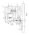
図2は、図1に示すシリンジが吸引動作を行っている様子を示す図であり、図3は、図1に示すシリンジが吐出動作を行っている様子を示す図である。 FIG. 2 is a diagram illustrating a state where the syringe illustrated in FIG. 1 is performing a suction operation, and FIG. 3 is a diagram illustrating a state where the syringe illustrated in FIG. 1 is performing a discharge operation.
貯留ウェル11は、チャネルプレート30の、マイクロチャネル32の上流側に位置する部分に設けられたものであり、底部11aにはマイクロチャネル32につながる開口111が設けられている。この貯留ウェル11には、細胞Cが分散した懸濁液Sが貯留される。
The
シリンジ12は、直動機構121の他、シリンジバレル122とシリンジプランジャ123を有するものである。直動機構121は、図2に示すようにシリンジユニット10の上フレーム141に固定されたモータ1211、このモータ1211の回転を伝える上下に延びるボールねじ1212、およびボールねじ1212が貫通したガイド部材1213を有する。ガイド部材1213は、モータ1211が正逆回転することでボールねじ1212に沿って上下動するものである。シリンジプランジャ123の後端部分は、このガイド部材1213の先端に着脱自在に取り付けられており、シリンジバレル122は、シリンジユニット10の下フレーム142に着脱自在に取り付けられている。したがって、モータ1211が所定方向に回転することで図2に示すようにシリンジプランジャ123が引き上げられ、貯留ウェル11に貯留された懸濁液Sがシリンジバレル122の先端1221からシリンジバレル122の内部1222に吸引される(吸引動作)。図2には、吸引動作を行いシリンジバレル122の内部1222に細胞Cを取込む様子が示されている。反対に、モータ1211が逆方向に回転することで図3に示すようにシリンジプランジャ123が押し下げられ、吸引した懸濁液Sがその先端1221から吐出される(吐出動作)。図3には、シリンジバレル122の内部1222に取り込んだ細胞Cを、吐出動作を行うことで開口111を経由させてマイクロチャネル32へ送出する様子が示されている。
The
本実施形態のシリンジユニット10によれば、吸引動作と吐出動作を連続して繰り返すことができ、シリンジプランジャ123およびシリンジバレル122を連続処理の途中で新品のものに交換することは不要である。ただし、連続処理を終えた後、新品のものに交換する必要が生じた場合には、シリンジプランジャ123およびシリンジバレル122はいずれも着脱自在に取り付けられているため、新品のシリンジに容易に交換することができる。また、シリンジの滅菌処理等のメンテナンスの際に、シリンジを取り外すことができ作業性が良好である。
According to the
さらに、シリンジバレル122には、内径の細い(例えば、0.5mm〜1.0mm)ものを用いて、十分な送液分解能を得ている。
Further, a
移動機構13は、下フレーム142の両脇それぞれに設けられたものであるが、図1では、一方の移動機構13しか図示されていない。いずれの移動機構13も、カムモータ131、偏心カム部材132、およびバネ部材133を有する。また、図1に示すように、ベース20上の、チャネルプレート30の両脇には一対の高さ規定ブロック43が配備されており、この図1には、シリンジユニット10の下フレーム142が、これら一対の高さ規定ブロック43の上に載置されている様子が示されている。バネ部材133は、シリンジユニット10の下フレーム142がこれら一対の高さ規定ブロック43の上に載置された状態になるまでシリンジユニット10を下方へ向けて付勢する。すなわち、バネ部材133は、シリンジバレル122の先端1221を貯留ウェル11の開口111の縁112(図2及び図3参照)に向けて付勢する付勢手段である。図3に示すシリンジユニット10は、下フレーム142が一対の高さ規定ブロック43の上に載置された状態のものであり、シリンジバレル122の先端1221が貯留ウェル11の開口111の縁112に押し付けられている。したがって、図3に示すシリンジバレル122の先端1221と貯留ウェル11の開口111の縁112との位置関係は、シリンジバレル122の先端1221が貯留ウェル11の開口111の縁112に押し付けられた押付関係にある。
Although the moving
図1に示すように、カムモータ131はベース20上に固定されたものであり、回転軸にはピニオンギア1311が固着されている。偏心カム部材132は、ラック部材1321と、偏心カム1322とからなるものである。ラック部材1321は、カムモータ131が回転することでベース20上を摺動するものである。偏心カム1322は、一対の高さ規定ブロック43に回転自在に軸支されたものであり、ラック部材1321が摺動することで回転する。この偏心カム1322は、回転することでカム面が、一対の高さ規定ブロック43に載置されたシリンジユニット10の下フレーム142を押し上げる。すなわち偏心カム部材132は、シリンジバレル122の先端1221を、バネ部材133の付勢力に抗して、懸濁液S中で貯留ウェル11の開口111の縁112から離間させるものである。図2に示すシリンジバレル122の先端1221と貯留ウェル11の開口111の縁112との位置関係は、シリンジバレル122の先端1221が貯留ウェル11に貯留された懸濁液S中で開口111の縁112から上方に離間した離間関係にある。よって、移動機構13は、シリンジ12を上下動させることで、シリンジバレル122の先端1221と貯留ウェル11の開口111の縁112との位置関係を、図2に示す離間関係と図3に示す押付関係との間で変化させるものである。さらに、本実施形態における移動機構13は、上記位置関係を、離間関係と押付関係との間で変化させるにあたり、シリンジバレル122の先端1221を貯留ウェル11に貯留された懸濁液S中に漬け込んだまま変化させるものである。したがって、本実施形態のシリンジユニット10によれば、上記位置関係が離間関係と押付関係との間で変化する間、シリンジバレル122の先端1221が懸濁液Sの液面から引き上げられることがなく、連続処理の途中でシリンジ交換も不要であることから空気の入り込みが防止される。このため、マイクロチャネル32内に気泡が混入することが抑えられる。また、シリンジバレル122には、内径の細いものを用いているため、気泡が混入することを抑えつつ十分な送液分解能を得ている。
As shown in FIG. 1, the
ここで、図2及び図3に示す移動機構13の変形例について説明する。以下の説明では、今まで説明した構成要素の名称と同じ名称の構成要素にはこれまで用いた符号を付して説明する。
Here, a modified example of the moving
図4は、図1に示すシリンジユニットの移動機構を図2及び図3それぞれに示すものとは異なる機構のものに代えた例を示す図である。 FIG. 4 is a view showing an example in which the moving mechanism of the syringe unit shown in FIG. 1 is replaced with a mechanism different from those shown in FIGS. 2 and 3 respectively.
図4に示す移動機構13も、付勢手段としてのバネ部材133を有するが、カムモータ131および偏心カム部材132の2つの構成要素に代えてピエゾアクチュエータ134を有する。このピエゾアクチュエータ134は、ベース20上で下フレーム142に固定されており、圧電効果あるいは逆圧電効果を利用して伸長することで、シリンジバレル122の先端1221を、バネ部材133の付勢力に抗して、懸濁液S中で貯留ウェル11の開口111の縁112から離間させるものである。図4には、伸長したピエゾアクチュエータ134が示されており、この図4における上記位置関係は離間関係にある。
The moving
なお、これまで説明した移動機構はいずれも、シリンジ12を上下動させることで上記位置関係を離間関係と押付関係との間で変化させるものであるが、貯留ウェル11を上下動させることで上記位置関係を離間関係と押付関係との間で変化させるものであってもよい。すなわち、移動機構は、シリンジ12と貯留ウェル11とを相対的に移動させることで、上記位置関係を離間関係と押付関係との間で変化させるものであればよい。
All of the moving mechanisms described so far change the positional relationship between the separation relationship and the pressing relationship by moving the
さらに、本実施形態のシリンジユニット10は、上記位置関係が離間関係にある状態でシリンジバレル122の先端1221と貯留ウェル11の開口111の縁112との間に存在する細胞あるいは気泡をその間から除去する除去手段を有する。
Furthermore, the
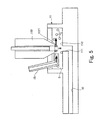
図5は、本実施形態のシリンジユニットが備える除去手段が細胞および気泡を除去している様子を示す図である。 FIG. 5 is a diagram showing a state where the removing means provided in the syringe unit of the present embodiment removes cells and bubbles.
この図5には、シリンジバレル122の先端1221に気泡Bが付着している様子が示されている。シリンジバレル122の先端を貯留ウェル11に貯留された懸濁液S中に最初に漬けたときには、シリンジバレル122の先端1221に気泡Bが付着してしまうことがある。また、貯留ウェル11に貯留された懸濁液中に溶け込んでいた空気が気泡になって表れることがある。さらに、上記位置関係が離間関係から押付関係に変化する際に、シリンジバレル122の先端1221と開口111の縁112との間に細胞Cが存在すると、その細胞Cを挟み込んでしまう恐れがある。図5に示す除去手段151は、シリンジバレル122の先端1221と貯留ウェル11の開口111の縁112との間に培養液を吹き付けるものである。この除去手段15によって培養液を吹き付けることで、その間に存在する気泡Bや細胞Cがその間から除去される。したがって、本実施形態のシリンジユニット10によれば、細胞Cを先端1221と縁112との間に挟み込んでしまうことを防止するとともに気泡Bがマイクロチャネル32内に混入することをより確実に抑えることができる。
FIG. 5 shows a state in which bubbles B are attached to the
図6は、図5に示す除去手段に代えブラシ部材を設けて気泡や細胞を除去している様子を示す図である。 FIG. 6 is a view showing a state where a brush member is provided in place of the removing means shown in FIG. 5 to remove bubbles and cells.
ここでの移動機構13は、上記位置関係が離間関係にある状態で、シリンジ12を水平方向(図6中の矢印参照)にも移動させることができるものである。なお、移動機構13は、シリンジ12と貯留ウェル11とを相対的に水平方向に移動させるものであればよい。また、図6に示す貯留槽11は底部11aにブラシ部材115を有する。このブラシ部材115は、底部11aに上向きに植毛され、シリンジ12が水平方向に移動することでシリンジバレル122の先端1221に摺擦し、その先端1221に付着した気泡Bや細胞Cを除去するものである。こうすることでも、細胞Cを先端1221と縁112との間に挟み込んでしまうことを防止するとともに気泡Bがマイクロチャネル32内に混入することをより確実に抑えることができる。
Here, the moving
続いて、図1に示す物質導入装置1を用いて細胞へ薬剤等の物質を導入する手順について説明する。この手順には、本発明の粒子送出方法の一実施形態である細胞送出方法の手順が含まれている。 Next, a procedure for introducing a substance such as a drug into a cell using the substance introduction apparatus 1 shown in FIG. 1 will be described. This procedure includes the procedure of the cell delivery method which is an embodiment of the particle delivery method of the present invention.
図7は、図1に示す物質導入装置を用いて細胞へ物質を導入する手順を示すフローチャートである。 FIG. 7 is a flowchart showing a procedure for introducing a substance into a cell using the substance introduction apparatus shown in FIG.
図7に示すフローチャートでは、マイクロチャネル32内の送液状態を安定させてから薬剤等の物質の導入処理を行う。まず、図1に示すベース20上にチャネルプレート20をセットし(ステップS1)、次いで、シリンジユニット10をセットする(ステップS2)。シリンジユニット10をセットした状態では、バネ部材133の付勢力により上記位置関係は図3に示す押付関係にある。続いて、送液安定用として貯留ウェル11に細胞が分散していない培養液を滴下するとともに(ステップS3)、培養液ウェル33にも培養液を滴下する(ステップS4)。次に、移動機構13のカムモータ131を回転させ偏心カム1322のカム面によって下フレーム142を押し上げ、シリンジ12を数百μm(例えば200μm〜300μm)上昇させ(ステップS5)、上記位置関係を押付関係から図2に示す離間関係にする。次いで、離間関係を維持したまま、図5に示す除去手段151によってシリンジバレル122の先端1221と貯留ウェル11の開口111の縁112との間に培養液を吹き付け(ステップS6)、その間に存在する気泡Bをその間から除去する。続いて、離間関係にある状態でシリンジ12に吸引動作を行わせ、シリンジバレル122の内部1222へ培養液を充填する(ステップS7)。次に、カムモータ131を回転させ偏心カム1322のカム面による押し上げを解除し、バネ部材133の付勢力によって上記位置関係を図3に示す押付関係に戻す(ステップS8)。すなわち、シリンジ12を下降させ、シリンジバレル122の先端1222を開口111に接続する。続いて、押付関係にある状態でシリンジ12に吐出動作を行わせ、ステップS7を実施することで内部に充填した培養液を、開口111を経由してマイクロチャネル32へ送出する(ステップS9)。ここで、シリンジプランジャ123が最前進位置にあるか否かを判定する(ステップS10)。すなわち、シリンジプランジャ123が完全に押し下げられ吐出動作が終了したか否かを判定し、終了していなければ吐出動作を続行させ(ステップS9)、終了していればステップS11へ進む。ステップS11では、マイクロチャネル32内の送液状態が安定したか否かを判定し、不安定であればステップS5へ戻り、安定していればステップS12へ進み、物質導入処理を開始する。
In the flowchart shown in FIG. 7, the introduction process of a substance such as a drug is performed after the liquid feeding state in the
物質導入処理ではまず、ステップS12で、貯留ウェル11に細胞Cが分散している懸濁液を滴下する(本発明にいう第1ステップの一例に相当)。次に、ステップS5と同様にしてシリンジ12を数百μm上昇させ(ステップS13)、上記位置関係を、シリンジバレル122の先端1221を貯留ウェル11に貯留された培養液中に漬け込んだまま離間関係にする。次いで、離間関係を維持したまま、ステップS6と同様にして培養液を吹き付け(ステップS14)、ステップS15へ進む。このステップS14では、細胞や貯留ウェル11に貯留された懸濁液中に溶け込んでいた空気による気泡が、シリンジバレル122の先端1221と開口111の縁112との間から除去される。ステップS15では、離間関係にある状態でシリンジ12に吸引動作を行わせ、シリンジバレル122の内部1222へ細胞Cを取り込む(本発明にいう第2ステップの一例に相当)。ステップS15に続くステップS16においては、ステップS8と同様にして上記位置関係を、シリンジバレル122の先端1221を貯留ウェル11に貯留された懸濁液中に漬け込んだまま図3に示す押付関係へ戻し(本発明にいう第3ステップの一例に相当)、ステップS17へ進む。ステップS17では、押付関係にある状態でシリンジ12に吐出動作を行わせ、ステップS15を実施することで内部に充填した細胞Cを、開口111を経由してマイクロチャネル32へ送出し(本発明にいう第4ステップの一例に相当)、図1に示す処理窓31が設けられた処理位置において、細胞を捕捉し細胞へ薬剤等の物質を導入する(ステップS18)。次に、ステップS10と同様にシリンジプランジャ123が最前進位置にあるか否かを判定し(ステップS19)、最前進位置に到達していなければ吐出動作を続行させ(ステップS17)、到達していればステップS20へ進む。ステップS20では、必要な数の細胞に物質が導入されたか否か、すなわち物質導入処理が終了したか否かを判定し、終了していなければステップS13へ戻り、物質導入処理が終了するまでステップS13からステップS20までを繰り返し実施する。一方、物質導入処理が終了すればこのフローチャートも終了になる。
In the substance introduction process, first, in step S12, a suspension in which the cells C are dispersed is dropped into the storage well 11 (corresponding to an example of the first step in the present invention). Next, the
以上説明した、細胞への物質導入の手順では、ステップS5からステップS20までを実施する間にシリンジバレル122の先端1221が懸濁液の液面から引き上げられることがなく、シリンジ交換を行わないことから空気の入り込みが防止されている。このため、気泡がマイクロチャネル32へ混入することが抑えられる。また、十分な送液分解能を得るために内径の細いシリンジを用いても、シリンジ交換が不要であり空気の入り込みが防止されているため、ステップS13からステップS20までを繰り返しても気泡が混入するといった問題が生じない。
In the procedure for introducing a substance into a cell as described above, the
続いて、本実施形態のシリンジユニットの応用例について説明する。 Then, the application example of the syringe unit of this embodiment is demonstrated.
本実施形態のシリンジユニット10では、図7に示すステップS6やステップS14において図5に示す除去手段15によって培養液を吹き付けることで、細胞Cや気泡Bを除去しているが、ステップSS16の実施中に細胞Cや気泡Bの除去を行う応用例についてまず説明する。
In the
図8は、シリンジによって細胞や気泡を除去している様子を示す図である。 FIG. 8 is a diagram showing a state where cells and bubbles are removed by a syringe.
図8に示すシリンジ12は、上記位置関係が離間関係から押付関係へ変化している最中(図7に示すステップS16の実施中)に吐出動作を開始し、シリンジバレル122の先端1221と開口111の縁112との間に存在する細胞Cや気泡Bが、その先端1221から吐出される懸濁液Sの流れによって貯留ウェル11の周壁側へ除去される。
The
こうすることで、細胞Cの挟み込みやマイクロチャネル32への気泡Bの混入をより確実に抑えることができる。
By doing so, it is possible to more reliably suppress the sandwiching of the cells C and the mixing of the bubbles B into the
また、貯留ウェルの開口の縁を、底部の、その縁を囲う部分よりも上方突出したものにすることで、細胞の挟み込みを防止することも可能である。 In addition, it is possible to prevent the cells from being caught by making the edge of the opening of the reservoir well project above the portion of the bottom that surrounds the edge.
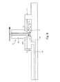
図9は、貯留ウェルの開口の縁を一段高くして細胞の挟み込みを防止している様子を示す図であり、図10は、貯留ウェルの開口の縁を囲う部分を一段低くして細胞の挟み込みを防止している様子を示す図である。 FIG. 9 is a diagram showing a state in which the edge of the opening of the reservoir well is further raised to prevent the sandwiching of cells, and FIG. 10 is a diagram showing a state in which the portion surrounding the edge of the opening of the reservoir well is lowered further. It is a figure which shows a mode that pinching is prevented.
図9に示す貯留ウェル11の開口111の縁112は、底部11aの、その縁112を囲う部分113よりも細胞Cの直径(浮遊状態で5〜20μm)以上突出したものである。また、図10に示す底部11aの、開口111の縁112を囲う部分113は、その縁112よりも細胞Cの直径以上窪んだ溝である。これらのようにすることで、シリンジバレル122の先端1221と開口111の縁112との間に細胞Cを挟み込む可能性がより低くなる。また、シリンジバレル122の先端1221が接する縁112の面積が小さくなり、先端1221の接触圧が高められる。
The
図11は、図9に示す貯留ウェルの開口の縁を曲面にした例を示す図である。 FIG. 11 is a diagram showing an example in which the edge of the opening of the storage well shown in FIG. 9 is curved.
図11に示す貯留ウェル11の開口111の縁112は、上方に向かって突出しており、突出先端面1121が上に凸の曲面である。上に凸の曲面にすることで細胞Cが開口111の縁112に留まらずに転がり落ち、細胞Cの挟み込みの可能性がより一段と低くなる。
The
次に、長時間の連続処理を行っていると、貯留ウェル11内では、底部11aに細胞Cが沈殿してしまう等の細胞Cの偏在がどうしても起こりやすくなる。このため、偏在した細胞Cを分散させる応用例について説明する。 Next, when continuous processing is performed for a long time, uneven distribution of the cells C such as the precipitation of the cells C on the bottom 11a is apt to occur in the storage well 11 by any means. For this reason, the application example which disperse | distributes the unevenly distributed cell C is demonstrated.
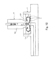
図12は、貯留ウェルの底部に沈殿した細胞をシリンジによって分散させている様子を示す図である。 FIG. 12 is a diagram illustrating a state in which cells precipitated on the bottom of the storage well are dispersed by a syringe.
図12に示すシリンジ12は、上記位置関係が離間関係にある状態で、吸引動作と吐出動作を繰り返し行い、シリンジバレル122の先端1221から懸濁液Sを出入りさせる。この懸濁液Sの出入りによって貯留ウェル11内が攪拌され、底部11aに沈殿していた細胞Cが分散される。
The
最後に、図7に示すステップS12を自動化し、長時間の連続処理をより行いやすくしたシリンジユニット10について説明する。
Finally, the
図13は、図7に示すステップS12を自動化したシリンジユニットを示す図である。 FIG. 13 is a diagram showing a syringe unit obtained by automating step S12 shown in FIG.
図13に示すシリンジユニット10が備える貯留ウェル11には、不純物が入り込みことを防止するため蓋体115が設けられている。このシリンジユニット10は、貯留ウェル11やシリンジ12等の他、供給手段16やモニタ手段17や制御部18も有する。供給手段16は貯留ウェル11に、細胞Cが分散した懸濁液Sを供給するものである。図13に示す供給手段16は、バルブ161と供給パイプ162を有するものであり、このバルブ161が開かれることで、懸濁液Sが供給パイプ162を通って貯留ウェル11へ供給される。モニタ手段17は、貯留ウェル11に貯留されている懸濁液Sの液面S’の高さをモニタする液面センサである。また、制御部18は、モニタ手段17によるモニタ結果を受けて、液面S’の高さが所定の高さhよりも低くなった場合に、供給手段16のバルブ161を開け、懸濁液Sを貯留ウェル11へ供給させるものである。図13には上記位置関係が離間関係にある状態が示されており、ここにいう所定の高さhとは、この離間関係にある状態のシリンジバレル122の先端1221の高さよりもある程度高い高さをいう。図13に示すシリンジユニット10によれば、長時間の連続処理を行い、貯留ウェル11の液面S’が低下してきても、シリンジバレル122の先端1221が液面S’よりも上になることを避けることができ、長時間の連続運転を行っても、気泡がマイクロチャネル32内に混入することが抑えられる。
The storage well 11 provided in the
以上説明したように、本実施形態のシリンジユニット10によれば、気泡がマイクロチャネル32に混入することを抑えつつ十分な送液分解能を得ることができる。なお、本発明は、医学分野における細胞の送出に限らず、広く様々な分野に適用することができる。
As described above, according to the
Claims (10)
前記液体を貯留し、底部に前記所定の場所につながる開口が設けられた貯留槽、
前記液体を先端から吸引する吸引動作と吸引した液体を該先端から吐出する吐出動作とを行うポンプ、および
前記ポンプと前記貯留槽とを相対的に移動させることで、前記ポンプの先端と前記開口の縁との位置関係を、該ポンプの先端が前記貯留槽に貯留された液体中で前記開口の縁から上方に離間した離間関係と、該先端が該開口の縁に押し付けられた押付関係との間で変化させる移動機構を備え、
前記ポンプは、前記位置関係が、前記離間関係にある状態で前記吸引動作を行い前記粒子を内部に取込み、前記押付関係にある状態で前記吐出動作を行い該粒子を送出するものであり、
前記移動機構が、前記位置関係を、前記離間関係と前記押付関係との間で変化させるにあたり、前記先端を前記貯留槽に貯留された液体中に漬け込んだまま変化させるものであることを特徴とするポンプユニット。In a pump unit for sending the particles in a liquid in which the particles are dispersed to a predetermined place,
A storage tank in which the liquid is stored and an opening connected to the predetermined place is provided at the bottom,
A pump that performs a suction operation for sucking the liquid from the tip and a discharge operation for discharging the sucked liquid from the tip; and by relatively moving the pump and the storage tank, the tip of the pump and the opening The relationship in which the tip of the pump is spaced apart from the edge of the opening in the liquid stored in the storage tank, and the pressing relationship in which the tip is pressed against the edge of the opening. With a moving mechanism that changes between
The pump performs the suction operation in a state where the positional relationship is in the separation relationship, takes the particles inside, performs the discharge operation in a state in the pressing relationship, and sends the particles.
When the moving mechanism changes the positional relationship between the separation relationship and the pressing relationship, the moving mechanism changes the tip while being immersed in the liquid stored in the storage tank. Pump unit to be used.
前記貯留槽は、底部に上向きに植毛され、前記ポンプとこの貯留槽とが相対的に水平方向に移動することで該ポンプの先端に摺擦し該先端に付着した付着物を除去するブラシ部材を有するものであることを特徴とする請求項1記載のポンプユニット。The moving mechanism moves the pump and the storage tank in a relatively horizontal direction in a state where the positional relationship is in the separated relationship,
The storage tank is planted in the upward direction at the bottom, and the pump and the storage tank move relatively in the horizontal direction so that the brush is rubbed against the front end of the pump to remove deposits attached to the front end. The pump unit according to claim 1, comprising:
前記懸濁液を貯留し、底部に前記マイクロチャネルにつながる開口が設けられた貯留槽、
前記懸濁液を先端から吸引する吸引動作と吸引した懸濁液を該先端から吐出する吐出動作とを行うシリンジ、および
前記シリンジと前記貯留槽とを相対的に移動させることで、前記シリンジの先端と前記開口の縁との位置関係を、該シリンジの先端が前記貯留槽に貯留された懸濁液中で前記開口の縁から上方に離間した離間関係と、該先端が該開口の縁に押し付けられた押付関係との間で変化させる移動機構を備え、
前記シリンジは、前記位置関係が、前記離間関係にある状態で前記吸引動作を行い前記細胞を内部に取込み、前記押付関係にある状態で前記吐出動作を行い該細胞を送出するものであり、
前記移動機構が、前記位置関係を、前記離間関係と前記押付関係との間で変化させるにあたり、前記先端を前記貯留槽に貯留された懸濁液中に漬け込んだまま変化させるものであることを特徴とするシリンジユニット。In a syringe unit that sends the cells in a suspension in which the cells are dispersed into a microchannel,
A storage tank in which the suspension is stored and an opening connected to the microchannel is provided at the bottom,
A syringe that performs a suction operation for sucking the suspension from the tip and a discharge operation for discharging the sucked suspension from the tip, and by relatively moving the syringe and the storage tank, The positional relationship between the tip and the edge of the opening is the separation relationship in which the tip of the syringe is spaced upward from the edge of the opening in the suspension stored in the storage tank, and the tip is the edge of the opening. It has a moving mechanism that changes between the pressed pressing relationships,
The syringe performs the suction operation in a state where the positional relationship is in the separation relationship, takes the cells into the inside, and performs the discharge operation in a state in the pressing relationship to send the cells,
When the moving mechanism changes the positional relationship between the separation relationship and the pressing relationship, the moving mechanism changes the tip while being immersed in the suspension stored in the storage tank. Characteristic syringe unit.
前記液体を先端から内部に吸引する吸引動作と吸引した液体を該先端から外部に向けて吐出する吐出動作とを行うポンプの該先端と前記開口の縁との位置関係が、該ポンプの先端が前記貯留槽に貯留された液体中で前記開口の縁から上方に離間した離間関係にある状態で、該ポンプに該吸引動作を行わせ、前記粒子を該ポンプの内部に取込む第2ステップ、
前記位置関係を、前記離間関係から前記ポンプの先端が前記開口の縁に押し付けられた押付関係へ、該先端を前記貯留槽に貯留された液体中に漬け込んだまま変化させる第3ステップ、
前記位置関係が前記押付関係にある状態で前記ポンプに前記吐出動作を行わせ、前記第2ステップを実施することで該ポンプの内部に取り込んだ粒子を送出する第4ステップ、および
前記位置関係を前記押付関係から前記離間関係へ、前記ポンプの先端を前記貯留槽に貯留された液体中に漬け込んだまま変化させる第5ステップとを有し、
前記第2ステップから前記第5ステップまでを繰り返し実施することを特徴とする粒子送出方法。A first step of storing a liquid in which particles are dispersed in a storage tank provided with an opening connected to a predetermined place at the bottom;
The positional relationship between the tip of the pump that performs the suction operation for sucking the liquid from the tip to the inside and the discharge operation for discharging the sucked liquid from the tip to the outside and the edge of the opening is A second step of causing the pump to perform the suction operation in a state of being spaced apart from the edge of the opening in the liquid stored in the storage tank, and taking the particles into the pump;
A third step of changing the positional relationship from the separation relationship to a pressing relationship in which the tip of the pump is pressed against the edge of the opening while the tip is immersed in the liquid stored in the storage tank;
A fourth step of causing the pump to perform the discharge operation in a state in which the positional relationship is in the pressing relationship, and sending out particles taken into the pump by performing the second step; and From the pressing relationship to the separation relationship, a fifth step of changing the tip of the pump while being immersed in the liquid stored in the storage tank,
A method for delivering particles, comprising repeatedly performing the second step to the fifth step.
前記懸濁液を先端から内部に吸引する吸引動作と吸引した懸濁液を該先端から外部に向けて吐出する吐出動作とを行うシリンジの該先端と前記開口の縁との位置関係が、該シリンジの先端が前記貯留槽に貯留された懸濁液中で前記開口の縁から上方に離間した離間関係にある状態で、該シリンジに該吸引動作を行わせ、前記細胞を該シリンジの内部に取込む第2ステップ、
前記位置関係を、前記離間関係から前記シリンジの先端が前記開口の縁に押し付けられた押付関係へ、該先端を前記貯留槽に貯留された懸濁液中に漬け込んだまま変化させる第3ステップ、
前記位置関係が前記押付関係にある状態で前記シリンジに前記吐出動作を行わせ、前記第2ステップを実施することで該シリンジの内部に取り込んだ細胞を送出する第4ステップ、および
前記位置関係を前記押付関係から前記離間関係へ、前記シリンジの先端を前記貯留槽に貯留された懸濁液中に漬け込んだまま変化させる第5ステップとを有し、
前記第2ステップから前記第5ステップまでを繰り返し実施することを特徴とする細胞送出方法。A first step of storing a suspension in which cells are dispersed in a storage tank provided with an opening connected to the location of the microchannel at the bottom;
The positional relationship between the tip of the syringe that performs the suction operation for sucking the suspension from the tip to the inside and the discharge operation for discharging the sucked suspension from the tip to the outside and the edge of the opening is In the state where the tip of the syringe is spaced apart from the edge of the opening in the suspension stored in the storage tank, the syringe is caused to perform the suction operation, and the cell is placed inside the syringe. The second step to capture,
A third step of changing the positional relationship from the separation relationship to a pressing relationship in which the tip of the syringe is pressed against an edge of the opening while being immersed in the suspension stored in the storage tank;
A fourth step of causing the syringe to perform the discharge operation in a state where the positional relationship is the pressing relationship, and sending out cells taken into the syringe by performing the second step; and A fifth step of changing the tip of the syringe from the pressing relationship to the separating relationship while being immersed in the suspension stored in the storage tank;
A cell delivery method comprising repeatedly performing the second step to the fifth step.
Applications Claiming Priority (1)
| Application Number | Priority Date | Filing Date | Title |
|---|---|---|---|
| PCT/JP2005/004180 WO2006095424A1 (en) | 2005-03-10 | 2005-03-10 | Pump unit, syringe unit, particle feeding method, and cell feeding method |
Publications (2)
| Publication Number | Publication Date |
|---|---|
| JPWO2006095424A1 JPWO2006095424A1 (en) | 2008-08-14 |
| JP4599397B2 true JP4599397B2 (en) | 2010-12-15 |
Family
ID=36953035
Family Applications (1)
| Application Number | Title | Priority Date | Filing Date |
|---|---|---|---|
| JP2007506956A Expired - Fee Related JP4599397B2 (en) | 2005-03-10 | 2005-03-10 | Pump unit, syringe unit, particle delivery method, and cell delivery method |
Country Status (3)
| Country | Link |
|---|---|
| US (1) | US20080166786A1 (en) |
| JP (1) | JP4599397B2 (en) |
| WO (1) | WO2006095424A1 (en) |
Families Citing this family (6)
| Publication number | Priority date | Publication date | Assignee | Title |
|---|---|---|---|---|
| JP2007166981A (en) * | 2005-12-22 | 2007-07-05 | Fujitsu Ltd | Injection apparatus and method |
| JP6557681B2 (en) * | 2014-05-10 | 2019-08-07 | ダイアグノロジックス・エルエルシー | System and apparatus for isolating or concentrating drugs using buoyancy |
| JP6942361B2 (en) | 2016-02-04 | 2021-09-29 | マサチューセッツ インスティテュート オブ テクノロジー | Modular organ microphysiological system with integrated pumping, leveling and sensing |
| US12065635B2 (en) | 2018-03-19 | 2024-08-20 | Massachusetts Institute Of Technology | Organ-on-chip platforms with reduced fluid volume |
| EP4472691A4 (en) * | 2022-02-04 | 2025-12-24 | Clickbio Inc | FLUID DISTRIBUTION MODULE |
| WO2025239257A1 (en) * | 2024-05-15 | 2025-11-20 | 武蔵エンジニアリング株式会社 | Powder supply device and powder supply method |
Citations (6)
| Publication number | Priority date | Publication date | Assignee | Title |
|---|---|---|---|---|
| JPH0387692U (en) * | 1989-12-26 | 1991-09-06 | ||
| JP2002372151A (en) * | 2001-06-18 | 2002-12-26 | Kazumasa Onishi | Diaphragm and diaphragm valve |
| JP2003019455A (en) * | 2001-07-09 | 2003-01-21 | Matsushita Electric Ind Co Ltd | Fluid ejection device and fluid ejection method |
| JP2004037446A (en) * | 2002-02-13 | 2004-02-05 | Becton Dickinson & Co | System and method for ensuring the integrity and operation of a pipetting device for handling liquid samples |
| WO2004090090A1 (en) * | 2003-04-09 | 2004-10-21 | Effector Cell Institute Inc. | Apparatus for detecting cell chemotaxis |
| JP2006158335A (en) * | 2004-12-09 | 2006-06-22 | Olympus Corp | Dividedly injecting device and culture treatment apparatus |
Family Cites Families (8)
| Publication number | Priority date | Publication date | Assignee | Title |
|---|---|---|---|---|
| US3188181A (en) * | 1963-03-11 | 1965-06-08 | Parke Davis & Co | Serial dilution machine |
| US4478094A (en) * | 1983-01-21 | 1984-10-23 | Cetus Corporation | Liquid sample handling system |
| JPH0513198U (en) * | 1991-08-05 | 1993-02-23 | 宇宙開発事業団 | Biological sample transfer device |
| JP3584732B2 (en) * | 1998-05-08 | 2004-11-04 | 松下電器産業株式会社 | Dispensing device, dispensing method and dispensing tip mounting method |
| US6379625B1 (en) * | 1999-12-23 | 2002-04-30 | Peter Zuk, Jr. | Apparatus comprising a disposable device and reusable instrument for synthesizing chemical compounds, and for testing chemical compounds for solubility |
| US6245297B1 (en) * | 1999-04-16 | 2001-06-12 | Pe Corporation (Ny) | Apparatus and method for transferring small volumes of substances |
| JP4434416B2 (en) * | 2000-03-23 | 2010-03-17 | エイブル株式会社 | High-pressure culture apparatus and method for growing deep water organisms using the same |
| JP4278365B2 (en) * | 2002-11-22 | 2009-06-10 | 富士通株式会社 | Transduced cell production device |
-
2005
- 2005-03-10 JP JP2007506956A patent/JP4599397B2/en not_active Expired - Fee Related
- 2005-03-10 US US11/885,438 patent/US20080166786A1/en not_active Abandoned
- 2005-03-10 WO PCT/JP2005/004180 patent/WO2006095424A1/en not_active Ceased
Patent Citations (6)
| Publication number | Priority date | Publication date | Assignee | Title |
|---|---|---|---|---|
| JPH0387692U (en) * | 1989-12-26 | 1991-09-06 | ||
| JP2002372151A (en) * | 2001-06-18 | 2002-12-26 | Kazumasa Onishi | Diaphragm and diaphragm valve |
| JP2003019455A (en) * | 2001-07-09 | 2003-01-21 | Matsushita Electric Ind Co Ltd | Fluid ejection device and fluid ejection method |
| JP2004037446A (en) * | 2002-02-13 | 2004-02-05 | Becton Dickinson & Co | System and method for ensuring the integrity and operation of a pipetting device for handling liquid samples |
| WO2004090090A1 (en) * | 2003-04-09 | 2004-10-21 | Effector Cell Institute Inc. | Apparatus for detecting cell chemotaxis |
| JP2006158335A (en) * | 2004-12-09 | 2006-06-22 | Olympus Corp | Dividedly injecting device and culture treatment apparatus |
Also Published As
| Publication number | Publication date |
|---|---|
| WO2006095424A1 (en) | 2006-09-14 |
| JPWO2006095424A1 (en) | 2008-08-14 |
| US20080166786A1 (en) | 2008-07-10 |
Similar Documents
| Publication | Publication Date | Title |
|---|---|---|
| EP2521525B1 (en) | Method and device for generating a nanoaerosol | |
| US20180264731A1 (en) | System and method for delivering ink into a 3d printing apparatus | |
| JP4599397B2 (en) | Pump unit, syringe unit, particle delivery method, and cell delivery method | |
| US9855747B2 (en) | Inkjet head and inkjet device | |
| EP2103266B1 (en) | Flushing device for a puncturing device | |
| EP2237900A2 (en) | System for storing and dispensing liquid cleaning additive for a high-pressure cleaning device | |
| DE102016111214B3 (en) | Device for powder dosing for chemical production processes under clean room conditions, use thereof and dosing method | |
| WO2023020981A2 (en) | Dispenser device, centrifuge comprising such a dispenser device, and method for cleaning dispenser nozzles | |
| EP3924170A1 (en) | Method and cleaning system for cleaning three-dimensional objects | |
| JP2008089181A (en) | Minute amount distribution device for liquid medium | |
| CN100351081C (en) | Printing method of printing press | |
| CN109427620B (en) | Pump device, processing liquid supply device, substrate processing device, liquid discharge method, and liquid replacement method | |
| LU101085B1 (en) | Method for setting a cell concentration and / or particle concentration in a dispensing device | |
| JP2019044619A (en) | Pump device, processing liquid supply device, and substrate processing device | |
| EP2097722B1 (en) | Device and method for metering media | |
| EP2701855B1 (en) | Device for coating a tubular medical technical component with adhesive | |
| KR20220085075A (en) | Chemical lquid circulation apparatus, chemical lquid dispensing apparatus, and chemical lquid supply system having the same | |
| WO2016088798A1 (en) | Treatment liquid supply device using syringe, and wet treatment device | |
| JP3878667B2 (en) | Dispensing system | |
| JP2025016912A (en) | Cell injection device, cell collection auxiliary tool, and cell collection method | |
| JP6705925B2 (en) | Wet processing device using a syringe | |
| JPS63131067A (en) | Pumping distributor | |
| TWI510379B (en) | An ink tank, and an ink stirring method using the ink tank | |
| DE202007014392U1 (en) | Device for the metered filling of media | |
| JP2006181762A (en) | Suction device, droplet discharge device, and microarray manufacturing device |
Legal Events
| Date | Code | Title | Description |
|---|---|---|---|
| A521 | Request for written amendment filed |
Free format text: JAPANESE INTERMEDIATE CODE: A523 Effective date: 20100628 |
|
| TRDD | Decision of grant or rejection written | ||
| A01 | Written decision to grant a patent or to grant a registration (utility model) |
Free format text: JAPANESE INTERMEDIATE CODE: A01 Effective date: 20100921 |
|
| A01 | Written decision to grant a patent or to grant a registration (utility model) |
Free format text: JAPANESE INTERMEDIATE CODE: A01 |
|
| A61 | First payment of annual fees (during grant procedure) |
Free format text: JAPANESE INTERMEDIATE CODE: A61 Effective date: 20100927 |
|
| R150 | Certificate of patent or registration of utility model |
Free format text: JAPANESE INTERMEDIATE CODE: R150 |
|
| FPAY | Renewal fee payment (event date is renewal date of database) |
Free format text: PAYMENT UNTIL: 20131001 Year of fee payment: 3 |
|
| LAPS | Cancellation because of no payment of annual fees |