JP4609727B2 - Labeling equipment - Google Patents
Labeling equipment Download PDFInfo
- Publication number
- JP4609727B2 JP4609727B2 JP2006083369A JP2006083369A JP4609727B2 JP 4609727 B2 JP4609727 B2 JP 4609727B2 JP 2006083369 A JP2006083369 A JP 2006083369A JP 2006083369 A JP2006083369 A JP 2006083369A JP 4609727 B2 JP4609727 B2 JP 4609727B2
- Authority
- JP
- Japan
- Prior art keywords
- label
- label sticking
- sticking
- labeling
- location
- Prior art date
- Legal status (The legal status is an assumption and is not a legal conclusion. Google has not performed a legal analysis and makes no representation as to the accuracy of the status listed.)
- Expired - Fee Related
Links
Images
Landscapes
- Labeling Devices (AREA)
Description
本発明は、走行可能な手押し台車式のラベル貼付装置と、貼付対象にラベルを貼り付けるラベル貼付用箇所にて前記ラベル貼付装置を位置決めする位置決め手段とを備えたラベル貼付設備に関する。 The present invention relates to a label sticking facility including a travelable cart type label sticking device and positioning means for positioning the label sticking device at a label sticking location for sticking a label to a sticking target.
上記ラベル貼付設備は、コンベヤ等にて搬送される物品等の貼付対象にラベルを自動的に貼り付けるラベル貼付装置を、位置決め手段にてラベル貼付用箇所に位置決めさせた状態で設置して、ラベル貼付用箇所に対応した貼付位置に位置する貼付対象、例えばコンベヤ等により貼付位置に搬送される物品にラベルを自動的に貼り付けるものである。 The labeling equipment is installed with a labeling device that automatically attaches a label to an object to be attached such as an article conveyed by a conveyor, etc., with the positioning means positioned at the location for labeling. A label is automatically pasted to a pasting object located at a pasting position corresponding to a pasting location, for example, an article conveyed to the pasting position by a conveyor or the like.
上記のように構成されたラベル貼付設備の従来例として、ラベル貼付装置が、その台車部分に複数のキャスターを備えて走行可能に構成され、そして、位置決め手段として複数のジャッキボルトが、ラベル貼付装置に備えられたものがある(例えば、特許文献1参照。)。 As a conventional example of a labeling facility configured as described above, a labeling device is configured to be able to travel with a plurality of casters in its carriage part, and a plurality of jack bolts as positioning means include a labeling device. (See, for example, Patent Document 1).
このようなラベル貼付設備では、作業者が、手押し作業によりラベル貼付装置をラベル貼付用箇所まで移動させ、各ジャッキボルトを下向きの伸張方向に回転操作して、キャスターの下端面よりも下方に突出させて、ジャッキボルトにてラベル貼付装置を支持する状態にすることで、ラベル貼付装置をラベル貼付用箇所に位置決めできるようになっている。 In such a labeling facility, the operator manually moves the labeling device to the labeling location, rotates each jack bolt in the downward extension direction, and projects downward from the lower end surface of the caster. Then, the label sticking device can be positioned at the label sticking position by supporting the label sticking device with the jack bolt.
ところで、上述のようなラベル貼付設備においては、ラベル貼付装置が故障して設備の稼動が停止した場合には、故障したラベル貼付装置を予備のラベル貼付装置と交換して、設備の稼動を復旧させる。ラベル貼付装置の交換作業では、まず、故障したラベル貼付装置を位置決めしている位置決め手段の位置決め作用を解除し、故障したラベル貼付装置を走行移動させてラベル貼付用箇所から離脱させた後、予備のラベル貼付装置をラベル貼付用箇所まで走行移動させて、ラベル貼付用箇所にラベル貼付用の向きで正しく位置する状態で、位置決め手段を作用させて予備のラベル貼付装置を位置決めすることで、交換作業が完了する。 By the way, in the labeling equipment as described above, if the labeling device fails and the operation of the equipment is stopped, the failed labeling device is replaced with a spare labeling device to restore the operation of the equipment. Let In exchanging the labeling device, first, the positioning means for positioning the failed labeling device is released, the failed labeling device is moved away from the place for labeling, Replace the labeling device by moving the labeling device to the labeling location and positioning the spare labeling device with the positioning means in the correct position for labeling at the labeling location. The work is complete.
ところが、上記従来のラベル貼付設備であると、ラベル貼付装置が故障したときの交換作業に手間取る場合があり、設備の稼動を復旧させるまでに時間がかかる場合があった。 However, in the case of the above conventional labeling equipment, it may take time to replace the equipment when the labeling equipment fails, and it may take time to restore the operation of the equipment.
説明を加えると、上記従来のラベル貼付設備であると、ラベル貼付装置の走行移動を規制するものがないため、ラベル貼付装置の前後左右の位置並びに向きを自由に変更させながらラベル貼付箇所に位置させることができるものであるため、ラベル貼付装置の交換作業において、作業者がラベル貼付装置をラベル貼付箇所にラベル貼付用向きに向いた状態で正しく位置させるためには、ラベル貼付装置を単に移動させるだけでなく、ラベル貼付装置の位置及び向きが正しくなるように、交換作業を行う作業者が手押し作業により調整する必要があった。 In addition, since there is nothing that regulates the travel movement of the label applicator with the conventional label applicator described above, the label applicator is positioned at the label applicator position while freely changing the front and rear, left and right positions and orientation of the label applicator. In order to place the label applicator correctly at the label applicator in the label application orientation, simply move the label applicator when replacing the label applicator. In addition, it is necessary for the operator who performs the replacement work to adjust the position and the orientation of the label sticking apparatus by hand work so that the position and orientation of the label sticking apparatus are correct.
つまり、ラベル貼付装置の位置及び向きが正しいかどうかを確認するため、位置決め手段にて位置決めした後、ラベル貼付装置を作動させ、貼付対象に実際にラベルを貼り付ける動作確認を行ってみて、ラベル貼付位置において貼付対象に対して適正にラベルが貼り付けられない場合には、位置決め手段による位置決め作用を解除して、再びラベル貼付装置を移動させて位置決めした後、改めて動作確認を行うということを繰り返すことになり、ラベル貼付装置をラベル貼付箇所に正しい位置及び向きとなる状態で位置決めするまでに時間がかかってしまい、設備の稼動を復旧させるまでに時間がかかるといった問題があった。 In other words, in order to check whether the position and orientation of the label applicator is correct, after positioning by the positioning means, the label applicator is operated and the operation check for actually attaching the label to the object to be applied is performed. If the label cannot be properly applied to the object to be applied at the application position, the positioning operation by the positioning means is canceled, the label application device is moved again and positioned, and then the operation is confirmed again. Repeatedly, there was a problem that it took time to position the label sticking device in the correct position and orientation at the label sticking location, and it took time to restore the operation of the equipment.
また、上記したラベル貼付装置の位置調整を伴う交換作業を上手く行えないユーザーにおいては、サービスマンに依頼してラベル貼付装置の交換作業を行ってもらわなければならない場合があり、そのような場合には、ラベル貼付設備の稼動が再開するまで、手動操作式のラベラーを用いた手作業によるラベルの貼付作業で対応するため、設備の稼動が再開するまでは生産性が低下してしまうという問題もあった。 In addition, users who cannot perform the replacement work that involves adjusting the position of the labeling device described above may require a serviceman to replace the labeling device. Will be handled by manual labeling using a manually operated labeler until the operation of the labeling facility is resumed, resulting in a decrease in productivity until the operation of the facility is resumed. there were.
ちなみに、ラベル貼付装置が、コンベヤ等の搬送装置により搬送される物品に対してラベルを貼り付けるものである場合、コンベヤの搬送速度が高速化した現在においては手作業でのラベルの貼り付けによる対応ができない場合もあり、そのような場合には、稼動中のラベル貼付装置が故障してラベル貼付設備の稼動が停止すると、ラベル貼付設備の稼動が再開されるまでの長時間に亘って生産性を極端に低下させることになるため、上述の問題が特に顕著であった。 By the way, if the labeling device attaches labels to articles that are transported by a transport device such as a conveyor, the handling speed of the conveyor has been increased, and now it can be handled manually. In such a case, if the labeling equipment in operation breaks down and the operation of the labeling equipment is stopped, the productivity over a long period of time until the operation of the labeling equipment is resumed. The above-mentioned problem is particularly remarkable.
本発明は上記実状に鑑みて為されたものであって、その目的は、ラベル貼付装置が故障して設備の稼動が停止した場合に、早期に設備の稼動を再開させることができるラベル貼付設備を提供する点にある。 The present invention has been made in view of the above circumstances, and its purpose is to provide a labeling facility capable of resuming the operation of the facility at an early stage when the labeling device fails and the operation of the facility is stopped. Is to provide
本発明にかかるラベル貼付設備は、走行可能な手押し台車式のラベル貼付装置と、貼付対象にラベルを貼り付けるラベル貼付用箇所にて前記ラベル貼付装置を位置決めする位置決め手段とを備えたラベル貼付設備であって、その第1特徴構成は、前記ラベル貼付装置における被案内部を前記ラベル貼付用箇所に向けて案内する案内部材が、前記ラベル貼付装置の横幅方向での位置を規制し且つ前記ラベル貼付装置の向きをラベル貼付用向きに規制する状態で、少なくとも前記ラベル貼付用箇所の近傍から前記ラベル貼付用箇所に案内するように設けられ、前記ラベル貼付装置は、走行移動用の車輪を横幅方向の左右の夫々について前後に備えて構成され、前記案内部材は、前記ラベル貼付用箇所において前記ラベル貼付装置を載置支持する設置台に、前記左右の車輪に対応して左右一対設けられ、かつ、前記被案内部として前記走行移動用の車輪を案内自在に構成され、前記設置台は、平面視で四隅に位置する箇所に上下軸心のボスを備えて構成され、前記複数のボスの夫々には、ねじ込み量が調節可能な状態でねじ込まれて接地面に接地する高さ調整部材が備えられて、前記左右一対の案内部材が高さ調節自在に構成され、前記左右一対の案内部材の夫々の後端部には、前記車輪が転動する使用位置と収納位置とに切換自在な可倒式スロープが設けられている点にある。 A label attaching facility according to the present invention includes a labeling device of a traveling cart type label attaching device and a positioning means for positioning the label attaching device at a label attaching portion for attaching a label to an object to be attached. And the 1st characteristic structure is that the guide member which guides the to-be-guided part in the said label sticking apparatus toward the said location for label sticking regulates the position in the horizontal width direction of the said label sticking apparatus, and the said label In a state in which the direction of the sticking device is restricted to the direction for sticking the label, the label sticking device is provided so as to guide at least the vicinity of the label sticking location to the label sticking location. Each of the left and right sides of the direction is provided in front and rear, and the guide member is provided to place and support the label sticking device at the label sticking point. A pair of left and right wheels are provided on the base corresponding to the left and right wheels, and the wheel for traveling is guided as the guided portion, and the installation base is located at four corners in plan view. Each of the plurality of bosses is provided with a height adjusting member that is screwed in a state where the screwing amount is adjustable and is grounded to the grounding surface, and the pair of left and right guides. The member is configured to be adjustable in height, and a tiltable slope that can be switched between a use position where the wheel rolls and a storage position is provided at the rear end of each of the pair of left and right guide members . In the point.
本発明の第1特徴によると、案内部材によりラベル貼付装置の横幅方向での位置が規制され、且つ、ラベル貼付装置の向きがラベル貼付用向きに規制された状態でラベル貼付装置をラベル貼付用箇所に向けて案内することができるので、ラベル貼付装置を正しい位置で正しい向きとなる状態でラベル貼付用箇所に手押し作業により移動させることが簡単に行うことができる。そして、ラベル貼付装置が正しい向きでラベル貼付用箇所に正しく位置した状態で位置決め手段にてラベル貼付装置を位置決めすればよく、ラベル貼付装置の設置作業を手早く行うことができる。 According to the first feature of the present invention, the label sticking device is used for label sticking in a state where the position of the label sticking device in the width direction is restricted by the guide member and the direction of the label sticking device is restricted to the label sticking direction. Since it can guide toward a location, it can be easily performed by manually pushing the label applicator to the location for label application in a correct orientation at the correct position. Then, the label sticking device may be positioned by the positioning means in a state where the label sticking device is correctly positioned in the label sticking position in the correct orientation, and the label sticking device can be installed quickly.
そして、ラベル貼付装置が故障してラベル貼付設備の稼動が停止した場合には、位置決め手段による位置決め作用を解除して故障したラベル貼付装置の被案内部を案内部材にて案内させながらラベル貼付用箇所から離脱させた後、予備のラベル貼付装置の被案内部を案内部材にて案内させながらラベル貼付用箇所に走行移動させ、予備のラベル貼付装置が正しい向きでラベル貼付用箇所に正しく位置した状態で位置決め手段にて予備のラベル貼付装置を位置決めすれば、ラベル貼付設備の稼動を再開させることができる。 When the labeling device fails and the operation of the labeling equipment is stopped, the positioning operation by the positioning means is canceled and the guided portion of the failed labeling device is guided by the guide member for labeling. After being removed from the location, the guided portion of the spare label sticking device is moved to the label sticking location while being guided by the guide member, and the spare label sticking device is correctly positioned in the label sticking location in the correct orientation. If the preliminary labeling device is positioned by the positioning means in the state, the operation of the labeling equipment can be resumed.
したがって、ラベル貼付装置が故障してラベル貼付設備の稼動が停止した場合には、ラベル貼付装置を案内部材にて被案内部が案内された状態で走行移動させることにより、ラベル貼付装置の交換作業を手早く行うことができ、ラベル貼付設備の稼動が停止する時間の短縮を図ることができる。 Therefore, if the labeling device fails and the operation of the labeling equipment stops, the labeling device can be replaced by moving the labeling device while the guided part is guided by the guide member. Can be performed quickly, and the time during which the operation of the labeling facility is stopped can be shortened.
このように、本発明の第1特長構成によると、ラベル貼付装置が故障して設備の稼動が停止した場合に、早期に設備の稼動を再開させることができるラベル貼付設備を得るに至った。 Thus, according to the 1st characteristic structure of this invention, when the label sticking apparatus failed and the operation | movement of an installation stopped, it came to obtain the label sticking equipment which can restart operation of an equipment at an early stage.
本発明の第2特徴構成は、本発明の第1特徴構成において、前記位置決め手段が、前記案内部材と一体状態に設けられた連結部材を、前記ラベル貼付装置に設けられた被連結部に連結することにより、位置決めするように構成されている点にある。 According to a second characteristic configuration of the present invention, in the first characteristic configuration of the present invention, the positioning means connects a connecting member provided integrally with the guide member to a connected portion provided in the label applying device. By doing so, there is a point configured to be positioned.
本発明の第2特徴によると、ラベル貼付装置に設けられた被連結部が案内部材と一体状態に設けられた連結部材に連結されると、ラベル貼付装置がラベル貼付用箇所にて位置決めされるので、被連結部及び連結部材を適切な位置に設けることにより、ラベル貼付装置をラベル貼付用箇所に位置した状態で安定して位置決めすることができる。また、連結部材が案内部材と一体状態に設けられているので、案内部材により案内されるラベル貼付用箇所に位置するラベル貼付装置における被連結部に対して、連結部材を精度よく設けることができ、これによりラベル貼付装置をラベル貼付用箇所に精度よく位置した状態で位置決めすることができる。 According to the second feature of the present invention, when the connected portion provided in the label sticking device is connected to the connecting member provided integrally with the guide member, the label sticking device is positioned at the location for label sticking. Therefore, by providing the connected portion and the connecting member at appropriate positions, the label sticking device can be stably positioned in a state where the label sticking device is located at the location for label sticking. Further, since the connecting member is provided integrally with the guide member, the connecting member can be provided with high accuracy with respect to the connected portion in the label sticking device located at the label sticking location guided by the guide member. Thus, the label sticking device can be positioned in a state where the label sticking device is accurately positioned at the label sticking location.
このように、本発明の第2特徴構成によると、ラベル貼付装置が故障して設備の稼動が停止した場合に、ラベル貼付装置をラベル貼付用箇所に精度よく安定的に位置した状態で、早期に設備の稼動を再開させることができるラベル貼付設備を得るに至った。 As described above, according to the second characteristic configuration of the present invention, when the labeling device breaks down and the operation of the facility is stopped, the labeling device is positioned accurately and stably at the location for labeling. Has led to a labeling facility that can resume the operation of the facility.
本発明の第3特徴構成は、本発明の第1又は第2特徴構成において、前記案内部材にて案内されて前記ラベル貼付用箇所に向けて走行する前記ラベル貼付装置の走行に対して前記ラベル貼付用箇所にて抵抗を付与する抵抗付与手段が設けられている点にある。 According to a third feature of the present invention, in the first or second feature of the present invention, the label with respect to travel of the label sticking device that is guided by the guide member and travels toward the label sticking portion. There exists in the point provided with the resistance provision means which provides resistance in the location for sticking.
本発明の第3特徴構成によると、案内部材によりラベル貼付装置がラベル貼付用箇所に案内されると、抵抗付与手段により走行抵抗が付与されるので、走行するラベル貼付装置の走行速度が減速され又は走行が停止される。 According to the third characteristic configuration of the present invention, when the label sticking device is guided to the label sticking position by the guide member, the running resistance is given by the resistance applying means, so the traveling speed of the traveling label sticking device is reduced. Or traveling is stopped.
したがって、作業者が、ラベル貼付装置を、案内部材により案内された状態で手押し作業により走行させるときに、ラベル貼付装置がラベル貼付用箇所に位置すると、手押し作業による走行速度が減速され又は走行が停止され、ラベル貼付装置をラベル貼付用箇所に停止させ易くなる。これにより、ラベル貼付装置を案内部材により案内された状態でラベル貼付用箇所に短時間で位置させることができる。 Therefore, when the operator travels the label sticking device by hand pushing in a state guided by the guide member, if the label sticking device is located at the label sticking position, the running speed by the hand pushing work is reduced or the running is stopped. It will be stopped and it will become easy to stop a label sticking apparatus to the location for label sticking. Thereby, the label sticking device can be positioned in the label sticking position in a short time in a state guided by the guide member.
このように、本発明の第3特徴構成によると、ラベル貼付装置をラベル貼付用箇所に位置させるまでの手押し作業を短時間で終えることができることになり、ラベル貼付装置が故障して設備の稼動が停止した場合に、一層早期に設備の稼動を再開させることができるラベル貼付設備を得るに至った。 As described above, according to the third characteristic configuration of the present invention, the manual pressing operation until the label sticking device is positioned at the label sticking position can be completed in a short time, and the label sticking device breaks down and the equipment is operated. In the event of a stoppage, a labeling facility that can restart the operation of the facility even earlier is obtained.
本発明の第4特徴構成は、本発明の第1〜第3特徴構成のうちのいずれか一つにおいて、前記ラベル貼付装置として、異なる前記ラベル貼付用箇所に設置され、且つ、異なる形態のラベル貼付作用部を備えるものを含む複数台が設けられ、異なる形態のラベル貼付作用部を付け替え装着自在に構成された交換用の予備のラベル貼付装置が設けられている点にある。 According to a fourth feature configuration of the present invention, in any one of the first to third feature configurations of the present invention, the label sticking device is installed at a different place for label sticking and has a different form of label. A plurality of units including those equipped with a sticking action part are provided, and a spare label sticking device for replacement configured to be able to replace and attach different types of label sticking action parts is provided.
本発明の第4特徴構成によると、複数台のラベル貼付装置に含まれる異なる形態のラベル貼付作用部の夫々を予備として用意しておけば、交換用の予備のラベル貼付装置を、異なる形態のラベル貼付作用部の数に対応した台数も備えておかなくても、予備のラベル貼付装置のラベル貼付作用部を、予備のラベル貼付作用部のうち故障したラベル貼付装置のラベル貼付作用部と同じ形態のラベル貼付作用部と付け替え装着することにより、故障したラベル貼付装置が設置されていたラベル貼付用箇所に予備のラベル貼付装置を設置することができ、ラベル貼付設備を復旧させることができる。 According to the fourth characteristic configuration of the present invention, if each of the different types of label application operation units included in the plurality of label application devices is prepared as a spare, the spare label application device for replacement can be changed to a different type. Even if the number corresponding to the number of label application units is not provided, the label application unit of the spare label application unit is the same as the label application unit of the failed label application unit of the spare label application unit. By attaching and replacing the label sticking operation part of the form, a spare label sticking device can be installed at the place for label sticking where the failed label sticking device was installed, and the label sticking equipment can be restored.
このように、本発明の第4特徴構成によると、ラベル貼付設備が、異なるラベル貼付用箇所に複数のラベル貼付装置が設置され、これらの複数のラベル貼付装置が異なる形態のラベル貼付作用部を備えるものを含むものを有するラベル貼付設備においても、設置コストが抑制され、しかも、いずれかのラベル貼付装置が故障して設備の稼動が停止した場合に、早期に設備の稼動を再開させることができるラベル貼付設備を得るに至った。 As described above, according to the fourth characteristic configuration of the present invention, the label application facility includes a plurality of label application devices installed at different label application locations, and the plurality of label application devices have different forms of label application operation units. Even in labeling equipment that includes what is provided, the installation cost is reduced, and if any labeling equipment fails and the equipment stops operating, the equipment can be restarted early. We came to obtain a labeling facility that could be used.
本発明の第5特徴構成は、本発明の第1〜第4特徴構成のうちのいずれか一つにおいて、前記ラベルの貼付対象を、貼付位置を経由して搬送する搬送装置が備えられ、前記ラベル貼付用箇所が前記貼付位置に対応して設定されている点にある。 According to a fifth feature of the present invention, in any one of the first to fourth feature configurations of the present invention, a transport device that transports the label pasting target via a pasting position is provided. The point for label sticking is that it is set corresponding to the sticking position.
本発明の第5特徴構成によると、ラベル貼付用箇所が搬送装置における搬送経路内の貼付位置に対応して設定されているので、ラベル貼付装置をラベル貼付方向にてラベル貼付用箇所に設置することで、搬送装置にて貼付位置に搬送されてくるラベルの貼付対象にラベル貼付装置によりラベルを貼り付けることができるようになる。しかも、前述の通り、ラベル貼付装置をラベル貼付方向にてラベル貼付用箇所に設置する場合には、案内部材より案内される位置まで手押し作業にて走行させるだけの簡単な操作と、その後の、押し作業における力の掛ける方向を、案内部材による案内方向に合わせるだけのさらに簡単な操作とにより、ラベル貼付装置をラベル貼付用箇所に移動させて、位置決め手段により位置決めすることで設置が完了する。つまり、貼付位置に対応する位置に案内部材を設けることにより、搬送装置の搬送経路内の貼付位置にてラベルが貼付対象に貼り付けられるように、ラベル貼付装置を誰でも簡単に設置することができるものとなる。 According to the fifth characteristic configuration of the present invention, the label sticking location is set corresponding to the sticking position in the transport path of the transport device, so the label sticking device is installed at the label sticking location in the label sticking direction. Thus, the label can be applied to the label application target conveyed by the conveying device to the application position by the label applying device. Moreover, as described above, when the label sticking device is installed at the label sticking position in the label sticking direction, a simple operation that is simply performed by hand pushing to the position guided by the guide member, The installation is completed by moving the label sticking device to the place for label sticking and positioning it by the positioning means by a simple operation that just matches the direction in which the force is applied in the pushing operation with the guide direction by the guide member. That is, by providing a guide member at a position corresponding to the sticking position, anyone can easily install the label sticking device so that the label is stuck to the sticking target at the sticking position in the transport path of the transport device. It will be possible.
したがって、搬送装置における貼付位置にて貼付対象にラベルを貼り付けるラベル貼付装置が故障した場合でも、故障したラベル貼付装置をラベル貼付用箇所から取り除いて、予備のラベル貼付装置或いは取り除いた後に修理されたものをラベル貼付箇所に、誰でも簡単に移動させて、位置決めさせることができるので、ラベル貼付設備が設置されている現場の作業者による迅速な対応が可能となり、ラベル貼付装置が設置された搬送装置が停止する時間の短縮を図ることができる。 Therefore, even if the label sticking device that sticks the label to the sticking target at the sticking position in the transport device fails, it is repaired after removing the failed label sticking device from the place for label sticking or removing the spare label sticking device. Anyone can easily move and position the item on the label affixing location, so it is possible for a worker on site where the label affixing facility is installed to respond quickly, and a label affixing device is installed. It is possible to shorten the time during which the transport device stops.
このように、本発明の第5特徴構成によると、ラベルの貼付対象を、貼付位置を経由して搬送する搬送装置が備えられた構成において、ラベル貼付装置が故障して設備の稼動が停止した場合に、早期に設備の稼動を再開させて、ラベルの貼付作業を再開させることができるラベル貼付設備を得るに至った。 As described above, according to the fifth characteristic configuration of the present invention, in the configuration including the transport device that transports the label pasting target via the pasting position, the operation of the facility is stopped due to the failure of the label pasting device. In some cases, the operation of the facility was resumed early, and a label attaching facility capable of restarting the label attaching operation was obtained.
本発明のラベル貼付設備の実施形態について図面に基づいて説明する。
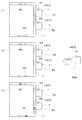
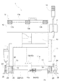
本ラベル貼付設備は、食品加工等を行う工場内の作業ラインに設けられている。作業ラインは、図1に示すように、生鮮食品用の第1ラインL1及び第2ラインL2と乾燥食品用の第3ラインL3とからなり、第1ラインL1には、ラベルの貼付対象としての発泡スチロール製の冷蔵用保冷容器Ws(以下、シッパーという。)を、ラベル貼付位置としての第1貼付位置P1及び第2貼付位置P2を経由して搬送する搬送装置としての第1搬送装置T1が設けられ、同様に、第2ラインL2には、ラベルの貼付対象としてのシッパーWsを、ラベル貼付位置としての第3貼付位置P3及び第4貼付位置P4を経由して搬送する搬送装置としての第2搬送装置T2が設けられている。また、第3ラインL3には、ラベルの貼付対象としての樹脂製の折り畳み式コンテナWf(以下、オリコンという。)を、ラベル貼付位置としての第5貼付位置P5及び第6貼付位置P6を経由して搬送する搬送装置としての第3搬送装置T3が設けられている。
An embodiment of a label attaching facility of the present invention will be described based on the drawings.
This labeling facility is provided in a work line in a factory that performs food processing and the like. As shown in FIG. 1, the work line is composed of a first line L1 and a second line L2 for fresh food and a third line L3 for dry food. A first transporting device T1 is provided as a transporting device for transporting a refrigerated cold storage container Ws (hereinafter referred to as a sipper) made of expanded polystyrene via a first pasting position P1 and a second pasting position P2 as label pasting positions. Similarly, the second line L2 is a second transport device that transports the sipper Ws as a label pasting target via the third pasting position P3 and the fourth pasting position P4 as the label pasting positions. A transport device T2 is provided. Further, on the third line L3, a resin foldable container Wf (hereinafter referred to as an Oricon) as a label application target is passed through a fifth application position P5 and a sixth application position P6 as label application positions. A third transport device T3 is provided as a transport device for transporting.
上記第1貼付位置P1〜第6貼付位置P6にてシッパーWsやオリコンWfにラベルを貼り付けるラベル貼付装置1が、第1貼付位置P1〜第6貼付位置P6のそれぞれに対応して設定されたラベル貼付用箇所としての第1設置位置S1〜第6設置位置S6に設置されている。また、工場内の適当なスペア置場Ssprには、稼動中のラベル貼付装置1のいずれかが故障した場合に、そのラベル貼付装置1と交換するための予備のラベル貼付装置1等が保管されている。
The
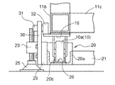
ラベル貼付装置1は、図1、図2、図6及び図7に示すように、汎用台車部Vとこれに取付けネジにより付け替え装着自在に設けられた貼付ユニット部Uとで構成されている。図3及び図6に示すように、汎用台車部Vは、車輪10a等で構成されたキャスター10を備えた台車11、台車11に固定設置された汎用装置部12、汎用装置部12の上面及び側面を覆うカバー13、ラベル貼付装置1の動作状態の正常及び異常を表示するシグナルタワー14等を備えている。
As shown in FIG. 1, FIG. 2, FIG. 6 and FIG. 7, the
図3及び図6に示すように、台車11は、背面側の下部フレーム11a及び前面側の下部フレーム11c(図4参照)、並びに、左右両側面の下部フレーム11b等で構成され、背面側の下部フレーム11aには、後述する位置決め手段HDの被連結部としての固定板15が、下部フレーム11aの下端高さより下方に先端部15aが突出する状態で設けられている。また、台車11の左右側面の下部フレーム11bの夫々には、設置状態において後述する押付ローラ32に対応する位置に被押付板16が水平面内で外方に張り出す状態で設けられている。
As shown in FIGS. 3 and 6, the
なお、汎用装置部12の制御部は、図示しないコネクタを介して貼付ユニット部Uと電気的に接続されており、貼付ユニット部Uを交換する際は、取り付けネジ及びコネクタを着脱するだけの簡単な作業で交換することができるようになっている。また、カバー13の天板部分13aは背面に設けられたカバー用蝶板13bにより揺動開閉自在に取り付けられており、天板部分13aを開状態にすることで、ラベルリールの交換作業やその他のメンテナンス作業が行えるようになっている。
The control unit of the general-
貼付ユニット部Uは、ラベル貼付装置1が設置されるラインで搬送される貼付対象(シッパーWs又はオリコンWf)に対応した貼付作用をするユニットである。例えば、第1ラインL1及び第2ラインL2に設置されたラベル貼付装置1であれば、貼付ユニット部Uとしてシリンダ式貼付ユニットUsが取り付けられ、第3ラインL3に設置されたラベル貼付装置1であれば、貼付ユニット部Uとしてエアブロー式貼付ユニットUaが取り付けられている。
The sticking unit U is a unit that performs a sticking action corresponding to a sticking object (sipper Ws or Oricon Wf) conveyed on a line where the
シリンダ式貼付ユニットUsは、突出位置と引退位置とに亘って出退動作するシリンダアーム17と、その先端に設けられた吸着板18とを備えている(図7参照)。例えば、図7に示すように、第1ラインL1の第1設置位置S1に設置されたラベル貼付装置1であると、貼付対象であるシッパーWsが第1貼付位置P1に位置するときに、シリンダアーム17が装置の前方に突出して突出位置となることで、ラベルを吸引保持している吸着板18がシッパーWsに当接して、ラベルが貼り付けられる。なお、吸着板18に吸引保持されるラベルは、引退位置に位置する吸着板18が、汎用装置12にセットされたラベルリールから汎用装置12の繰り出し機構により繰り出された帯状のラベル台紙から吸引することにより吸着板18に転写され、保持される。
The cylinder-type sticking unit Us includes a
また、エアブロー式貼付ユニットUaは、図示による説明は省略するが、ユニット本体に位置固定状態で設けられた吸着板に吸引保持されたラベルを、吸引保持を解除すると同時に噴出空気によりラベルを貼付対処のオリコンWfに対して吹き付けることにより非接触で貼り付けることができるようになっている。 The air blow type sticking unit Ua is not shown in the figure, but the label sucked and held by the suction plate provided in a fixed position on the unit body is released and the label is stuck by the blown air at the same time. It can be applied in a non-contact manner by spraying on the Oricon Wf.
前述のスペア置場Ssprには、予備のラベル貼付装置1と、予備のエアブロー式貼付ユニットUaが保管されている。スペア置場Ssprに保管されているラベル貼付装置1は、汎用台車部Vにシリンダ式貼付ユニットUsが予め取り付けられたものである。したがって、第1設置位置S1〜第4設置位置S4のラベル貼付装置1が故障した場合には、そのまま、予備のラベル貼付装置1と入れ替え設置すればよく、第5設置位置S5及び第6設置位置S6のラベル貼付装置1が故障した場合には、予備のラベル貼付装置1の貼付ユニット部Uを、シリンダ式貼付ユニットUsから予備のエアブロー式貼付ユニットUaに交換して、予備のラベル貼付装置1と入れ替え設置すればよい。つまり、シリンダ式貼付ユニットUsが取り付けられた予備のラベル貼付装置1の1台と、予備のエアブロー式貼付ユニットUaの1つとを保管しておくことで、異なる形態の貼付ユニット部Uを備えたラベル貼付装置1を含む6台のラベル貼付装置1のいずれが故障した場合でも、そのラベル貼付装置1に代えて予備のラベル貼付装置1を設置することができるようになっている。
A spare
このように、本ラベル貼付設備は、走行可能な手押し台車式で構成されたラベル貼付装置1として、異なるラベル貼付用箇所としての第1設置位置S1〜第6設置位置S6に設置され、且つ、異なる形態のラベル貼付作用部としての貼付ユニット部U(シリンダ式貼付ユニットUs、エアブロー式貼付ユニットUa)を備えるものを含む複数台が設けられ、貼付ユニット部Uを付け替え装着自在に構成された交換用の予備のラベル貼付装置1が設けられている。
Thus, this label sticking equipment is installed in the 1st installation position S1-the 6th installation position S6 as different label sticking places as
ラベル貼付装置1が設置される第1設置位置S1〜第6設置位置S6には、簡単かつ迅速にラベル貼付装置1を正しく設置できるように、設置台2が設けられている。以下に、設置台2の構成について詳しく説明する。なお、いずれの設置台2も同一の構成であるので、図1に示す第1ラインL1の第1設置位置S1に設置された設置台2を例に説明する。
An installation table 2 is provided at the first installation position S1 to the sixth installation position S6 where the
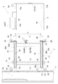
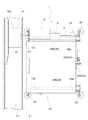
図2及び図3に示すように、設置台2は、左右一対のガイドレール20及び、この一対のガイドレール20が一定間隔を隔てて平行となるように連結固定する前側横フレーム21及び後側横フレーム22等で構成されている。図4にも示すように、各ガイドレール20の前後の両端部には、取付板23を介して、内面に雌ネジが刻まれたボス24が、雌ネジの軸心が上下方向となる状態で溶着されている。そして、ボス24には、雄ネジが刻まれたネジ棒と面広の接地部とからなる高さ調整部材25がねじ込まれている。
As shown in FIGS. 2 and 3, the installation table 2 includes a pair of left and right guide rails 20, and a front
つまり、設置台2の四隅にボス24が設けられており、これらの各ボス24にねじ込まれた高さ調整部材25のねじ込み量を調節することで、設置台2の傾斜を調整して左右のガイドレール20が同一の水平面内に収まるように、また、ラベル貼付装置1が設置台2上に載置された状態でラベル貼付装置1の貼付ユニット部Uが適切な高さで貼付作業ができるように、左右のガイドレール20の接地面からの高さを調整できるようになっている。
That is, the
なお、第1設置位置S1〜第6設置位置S6の全ての設置台2の設置位置及び高さ調整部材25のねじ込み量の調節は、本ラベル貼付設備の導入時に行うことになり、設置台2は調整された設置位置において、高さ調整部材25の接地部と設置面との摩擦により摩擦保持されるようになっている。
In addition, adjustment of the installation position of all the
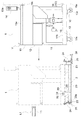
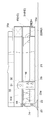
左右のガイドレール20の夫々は、図4及び図5に示すように、断面視U字形のフレーム部20a底面に、フレーム部20aと略同長の、同じく断面視U字形の案内部材20bが、フレーム部20aの底面に密着する状態で設けられている。案内部材20bは、そのU字形状により形成される溝部26の横幅Dが、ラベル貼付装置1のキャスター10の車輪10aの横幅と略同一となっている。また、左右のガイドレール20の案内部材20bにおける幅方向中心位置夫々の間の距離L(図2参照)は、ラベル貼付装置1の左右のキャスター10の取付間隔(直進状態における車輪10aの幅方向中心位置を基準とする)と同じ距離になっている。したがって、左右一対の案内部材20bは、ラベル貼付装置1における前方側の左右のキャスター10を第1設置位置S1に向けて案内することができるようになっている。前方側の左右のキャスター10は、本発明の被案内部に相当する。
As shown in FIGS. 4 and 5, each of the left and right guide rails 20 has a
左右の案内部材20bの夫々の後端には、蝶板27が設けられ、蝶板27の揺動側の板面27aを延長するように可倒式スロープ28が設けられている。可倒式スロープ28は、図5に示された使用位置と図7に示された収納位置とに切換自在となっている(図3参照)。装置後方側ほど溝部26の横幅D´が広くなる形状に加工された導入部20cが設けられており、後述するように、設置台2にラベル貼付装置1を載せる場合に、ラベル貼付装置1のキャスター10の車輪10aを可倒式スロープ28に沿って前方に転動させた後、溝部26内に入れ込め易くなっている。
A
本ラベル貼付設備は、上記した設置台2を設けることにより、作業者がラベル貼付装置1を第1設置位置S1に設置するときには、ラベル貼付装置1を設置台2の手間まで手押し移動させた後は、ラベル貼付装置1の前方側の左右キャスター10の車輪10aを夫々に対応する可倒式スロープ28に沿って前方に転動させた後、導入部20cの溝部26内に入れ込めるようにして前方へ手押し移動させようにすると、その位置からは、左右の案内部材20bにより前方側の左右キャスター10の車輪10aの転動による移動方向が案内されて、ラベル貼付装置1の横幅方向における走行位置及び向きが規制される状態となる。
In this label sticking facility, by providing the above-described
このようにラベル貼付装置1の横幅方向における走行位置及び向きが規制される状態で、作業者がラベル貼付装置1を手押し移動させることによりさらに第1設置位置S1への移動が進行すると、後方側の左右のキャスター10の車輪10aが可倒式スロープ28を登って、導入部20cに達して、その後は、後方側の左右のキャスター10の車輪10aの転動による移動方向も左右の案内部材20bにより案内されることになる。ラベル貼付装置1の前後左右の4つのキャスター10の全てが左右の案内部材20bにより案内されることにより、ラベル貼付装置1の向きがより狭い範囲内に規制されることになる。
In this state where the travel position and direction in the lateral width direction of the
設置台2は、ラベル貼付装置1の横幅方向における走行位置及び向きが規制される状態でラベル貼付装置1が走行するときの横幅方向における走行位置が、ラベル貼付装置1が第1設置位置S1に位置するときの横幅方向における位置となるように、また、ラベル貼付装置1の横幅方向における走行位置及び向きが規制される状態でラベル貼付装置1が走行するときの向きが、ラベル貼付装置1が第1設置位置S1に位置するときの向きとなるように設置状態が調整されている。なお、設置台2の設置状態の調整作業は、前述の通り、本ラベル貼付設備の導入時に設置業者のサービスマン等により行われる。
When the
このように本ラベル貼付設備では、ラベル貼付装置1における第1設置位置S1に案内する左右一対の案内部材20bが、ラベル貼付装置1の横幅方向での位置を規制し且つラベル貼付装置1の向きをラベル貼付用向きに規制する状態で、設けられている。
Thus, in this label sticking facility, the pair of left and
図2、図3及び図4に示すように、左右のガイドレール20の長手方向の前方寄りの箇所に押付ローラ32が設けられている。押付ローラ32は、その円周面の下端が、ラベル貼付装置1の前述した被押付板16の上面に当接することにより、設置台2上に載置されたラベル貼付装置1が貼付作業をする際に、貼付動作の反動等により生じるラベル貼付装置1の浮き上がり及び浮き上がりにより生じる揺れを防止するものである。
As shown in FIGS. 2, 3, and 4, a
押付ローラ32は、ガイドレール20のフレーム部20aの外方側部に設けられたローラ取付部材29に高さ調節可能に設けられた高さ調節部材30を介して設けられている。高さ調節部材30には、押付ローラ32をガイドレール20の幅方向を向く水平軸心周りに回転自在に支持する支持軸31が設けられており、高さ調節部材30のローラ取付部材29に対する取付け位置を上下に変更することにより、押付ローラ32の高さを変更設定することができるようになっている。
The
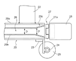
図2、図3及び図8に示すように、左右のガイドレール20の前方側端部には、案内部材23にて案内されて第1設置位置S1に向けて走行するラベル貼付装置1の走行に対して第1設置位置S1にて抵抗を付与する抵抗付与手段としての案内終端設定用のネジ33が設けられている。ネジ33は、ガイドレール20の前方側の取付板23に設けられたネジ孔にネジ頭33aを後方に向けた状態でねじ込まれている。ネジ33の取付板23における高さ方向における位置は、第1設置位置S1に向けて走行するラベル貼付装置1の前方側のキャスター10の車輪10aの回転軸心高さ付近に合わせてあり、車輪10aがネジ頭33aに当接する位置で走行するラベル貼付装置1の走行を阻止するようになっている。
As shown in FIGS. 2, 3, and 8, the
そして、ネジ33のねじ込み量を多くすれば、ネジ頭33aが前方側(図2及び図3で左方向)に位置することにより、案内部材23にて案内されて第1設置位置S1に向けて走行するラベル貼付装置1の走行をより前方側まで許容し、ネジ33のねじ込み量を少なくすれば、ネジ頭33aが後方側(図2及び図3で右方向)に位置することにより、案内部材23にて案内されて第1設置位置S1に向けて走行するラベル貼付装置1の走行をより後方側となるように制限する。したがって、後述する位置決め手段HDにてラベル貼付装置1が第1設置位置S1に位置決めされた状態で、ラベル貼付装置1の前方側キャスター10の車輪10aとネジ頭33aとの間に僅かな隙間ができるように、ネジ33のねじ込み量を設定しておくことにより、位置決め手段HDにより位置決めするにあたって、キャスター10の車輪10aが案内部材23にて案内された状態でラベル貼付装置1を、車輪10aがネジ頭33aに当接してラベル貼付装置1の走行が阻止されるまで押し当てるように手押し走行させることにより、予め、ラベル貼付装置1を第1設置位置S1から前後方向でのズレが小さい位置に簡単に停止させることができる。このように、ラベル貼付装置1を第1設置位置S1に極近い位置に停止させることにより、その後に位置決め手段HDによる位置決め操作を行い易くなる。
If the screwing amount of the
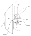
図8及び図9に示すように、前述の後側横フレーム22の背面における横方向中央付近位置には、トグル式のクランプ34が設けられている。クランプ34は、前方側のロック位置LPと後方側の解除位置RPとに切換操作自在に設けられたトグルレバー34a、トグルレバー34aの前後方向での位置切換操作に連動して、リンク機構の揺動端部34bを前後方向に揺動させるリンク機構、揺動端部34bに設けられたクランプ部34c等からなる。
As shown in FIGS. 8 and 9, a
本ラベル貼付設備では、図6、図7、及び図8に示すように、ラベル貼付装置1が設置台2に載置された状態であると、ラベル貼付装置1の背面側の下部フレーム11bに設けられた固定板15の先端部15aと設置台2の後側横フレーム22とが同じ高さとなるように構成されており、また、ラベル貼付装置1が設置台2上で第1設置位置S1に位置すると、ラベル貼付装置1の背面側の下部フレーム11bに設けられた固定板15の先端部15aが、設置台2の後側横フレーム22に当接するように、設置台2の設置位置が調節されている。
In this label sticking facility, as shown in FIGS. 6, 7, and 8, when the
そして、ラベル貼付装置1の固定板15の先端部15aが設置台2の後側横フレーム22に当接するときに、クランプ34のトグルレバー34aをロック位置LPに位置させることにより、固定板15の先端部15aを設置台2の後側横フレーム22及びクランプ部34cの間に挟んだ状態で、ラベル貼付装置1を第1設置位置S1に位置決めすることができる。
And when the front-end | tip
クランプ34の作動について説明すると、図9において実線で示されたロック位置LPに位置するトグルレバー34aを、紙面上方に引くようにして後方側に揺動操作して、仮想線で示された解除位置RPに切換操作すると、リンク機構の揺動端部34bに設けられたクランプ部34cが、実線で示されたクランプ位置CPから、仮想線で示された退避位置EPにまで退避作動する。
The operation of the
また、クランプ部34cは、揺動端部34bにねじ込まれており、揺動端部34bを挟み込むようにクランプ部34cにおける位置が変更自在に取り付けられた一対の固定ナット35により、揺動端部34bに対するねじ込み量が適切に調節された状態で固定されている。クランプ部34cの揺動端部34bにおける固定位置は、ラベル貼付装置1が設置台2に載置された状態でトグルレバー34aがロック位置LPに位置するときに、設置台2の後側横フレーム22の背面に先端部15aに接する状態で、クランプ部34cが先端部15aに当接して、位置決め作用するように調節されている。
The
ラベル貼付装置1を第1設置位置S1に設置する際や、第1設置位置S1から取り除く際に、案内部材20bに案内された状態で走行移動させるときには、クランプ34のトグルレバー34aを解除位置RPに位置させる。これにより、クランプ部34cが、図9に示すように実線で示されたクランプ位置CPから、仮想線で示された退避位置EPにまで退避作動するので、クランプ34の揺動端部34bやクランプ部34cが、固定板15の先端部15aの通過経路に干渉しなくなり、問題なくラベル貼付装置1を走行移動させることができる。
When the
このように、本ラベル貼付設備では、ラベル貼付装置1が設置台2に載置された状態で、ラベル貼付装置1を第1設置位置S1の位置で位置決めする位置決め手段HDが、後側横フレーム22、クランプ34、及び、固定板15により構成されており、案内部材20aと一体状態に設けられた連結部材が、後側横フレーム22及びクランプ34にて構成され、ラベル貼付装置1に設けられた被連結部が固定板15にて構成されている。そして、位置決め手段HDが、固定板15を後側横フレーム22及びクランプ34に連結することにより、ラベル貼付装置1を第1設置位置S1に位置決めするように構成されている。
Thus, in this label sticking equipment, the positioning means HD for positioning the
以上に説明したように、本ラベル貼付設備が備えられた第1ラインL1では、ラベル貼付装置1が、位置決め手段HDにより設置台2上で第1設置位置S1に位置決めされており、他のラベル貼付装置1も同様に、設置台2上で第2設置位置S2〜第6設置位置S6に位置決めされている。以下に、第3ラインL3の第5設置位置S5に設置されて稼動しているラベル貼付装置1が故障した場合に、スペア置場Ssprに保管されている予備のラベル貼付装置1と交換する場合を例にラベル貼付装置1の交換作業について説明する。
As described above, in the first line L1 provided with this label sticking facility, the
本例の場合、故障したラベル貼付装置1は、乾燥食品用の第3ラインL3における第5設置位置S5に設置されているものであるので、ラベル貼付装置1の貼付ユニット部Uとしては、第3ラインL3における貼付対象であるオリコンWfに対応したエアブロー式貼付ユニットUaが取り付けられている。したがって、故障したラベル貼付装置1とスペア置場Ssprに保管されている予備のラベル貼付装置1とを交換するためには、まず、予備のラベル貼付装置1の貼付ユニット部Uとしてのシリンダ式貼付ユニットUsを、同じくスペア置場Ssprに保管されている予備のエアブロー式貼付ユニットUaに交換する。そして、第5設置位置S5に設置されている故障したラベル貼付装置1を第5設置位置S5から取り除き、貼付ユニット部Uをエアブロー式貼付ユニットUaに交換後の予備のラベル貼付装置1を第5設置位置S5に設置する。
In the case of this example, the failed
第5設置位置S5に設置されている故障したラベル貼付装置1を第5設置位置S5から取り除くには、可倒式スロープ28を使用位置に切換え、クランプ34のトグルレバー34aをロック位置RPから解除位置RPに切換え操作して、ラベル貼付装置1を後方側に手押し走行させて、設置台2から下ろして、修理等の処置を行うため邪魔にならない場所に退避させる。この時点で、第5設置位置S5の設置台2にはラベル貼付装置1が乗っていない空き状態となっているので、貼付ユニット部Uをエアブロー式貼付ユニットUaに交換済みの予備のラベル貼付装置1を第5設置位置S5の設置台2に載せる。
To remove the failed
予備のラベル貼付装置1を第5設置位置S5の設置台2の後方位置まで手押し走行させて、使用位置になっている左右の可倒式スロープ28を使って、前方側の左右のキャスター10を左右のガイドレール20の導入部20cまで転動させるように予備のラベル貼付装置1を手押し走行させる。その後、前方側の左右のキャスター10が左右のガイドレール20の夫々の案内部材20bに案内される状態でさらに予備のラベル貼付装置1を手押し走行させ、キャスター10の車輪10aが案内終端設定用のネジ33に当接するまで手押し走行を継続させる。ネジ33に車輪10aが当接して予備のラベル貼付装置1をそれ以上手押し走行させることができなくなったら、クランプ34のトグルレバー34aを解除位置RPからロック位置RPに切換え操作して、可倒式スロープ28を収納位置に切換えて、交換作業が完了する。
The
上記の交換作業は、専門的な技術を要せず、工場内で加工作業を行っている作業者が行えるものであるから、本ラベル貼付設備であると、ラベル貼付装置1が故障した際には、迅速に予備のラベル貼付装置1と交換することができ、ラインの停止時間を極力短くすることができる。しかも、予備のラベル貼付装置1を、貼付ユニット部Uの種類の数だけ用意しておく必要がないので、異なる形態の貼付ユニット部Uを備えるものを含む複数台のラベル貼付装置1が設けられているラベル貼付設備においても、ラベル貼付装置1が故障したときに迅速に対応できるものを低コストで実現することができる。
Since the above replacement work does not require specialized technology and can be performed by a worker who is working in the factory, the
〔別実施形態〕
以下、別実施形態を列記する。
[Another embodiment]
Hereinafter, other embodiments are listed.
(4)上記実施形態では、案内部材としての左右一対の案内部材20bが設けられた設置台2が、高さ調整部材25の接地部と設置面との摩擦により調整された設置位置において摩擦保持されるものを例示したが、これに限らず、高さ調整部材25の接地部をアンカーボルト等により、設置台2がラベル貼付装置1の走行面に固定されたものでもよい。
(4) In the above embodiment, the
(5)上記実施形態では、位置決め手段が、後側横フレーム22、クランプ34、及び、固定板15により構成されたものを例示したが、位置決め手段としては、ジャッキボルトで構成されたものの他、案内部材20bの底面に、車輪10の幅より広い幅で、車輪10の直径より短い長さの位置決め用の長穴を設けて、車輪10が位置決め穴に落ち込んだ状態で車輪10の転動を規制するようにして、ラベル貼付装置1をラベル貼付用箇所に位置決めするものなど、位置決め手段の具体的構成は種々変更可能である。
(5) In the above embodiment, the positioning means is exemplified by the rear
Ws,Wf 貼付対象
P1〜P6 貼付位置
T1〜T3 搬送装置
U,Us,Ua ラベル貼付作用部
S1〜S6 ラベル貼付用箇所
HD 位置決め手段
1 ラベル貼付装置
10 被案内部
15 被連結部
20b 案内部材
22,34 連結部材
33 抵抗付与手段
Ws, Wf sticking objects P1 to P6 sticking positions T1 to T3 Conveying devices U, Us, Ua Label sticking action parts S1 to S6 Label sticking points HD Positioning means 1
Claims (5)
貼付対象にラベルを貼り付けるラベル貼付用箇所にて前記ラベル貼付装置を位置決めする位置決め手段とを備えたラベル貼付設備であって、
前記ラベル貼付装置における被案内部を前記ラベル貼付用箇所に向けて案内する案内部材が、前記ラベル貼付装置の横幅方向での位置を規制し且つ前記ラベル貼付装置の向きをラベル貼付用向きに規制する状態で、少なくとも前記ラベル貼付用箇所の近傍から前記ラベル貼付用箇所に案内するように設けられ、
前記ラベル貼付装置は、走行移動用の車輪を横幅方向の左右の夫々について前後に備えて構成され、
前記案内部材は、前記ラベル貼付用箇所において前記ラベル貼付装置を載置支持する設置台に、前記左右の車輪に対応して左右一対設けられ、かつ、前記被案内部として前記走行移動用の車輪を案内自在に構成され、
前記設置台は、平面視で四隅に位置する箇所に上下軸心のボスを備えて構成され、
前記複数のボスの夫々には、ねじ込み量が調節可能な状態でねじ込まれて接地面に接地する高さ調整部材が備えられて、前記左右一対の案内部材が高さ調節自在に構成され、
前記左右一対の案内部材の夫々の後端部には、前記車輪が転動する使用位置と収納位置とに切換自在な可倒式スロープが設けられているラベル貼付設備。 A hand cart type label sticking device capable of traveling;
A labeling facility comprising positioning means for positioning the labeling device at a location for labeling that affixes a label to a target,
A guide member that guides the guided portion of the label sticking device toward the location for label sticking restricts the position of the label sticking device in the width direction and restricts the direction of the label sticking device to the direction for label sticking. In a state to be provided to guide at least the label application location from the vicinity of the label application location ,
The label sticking device is configured to include front and rear wheels for traveling movement on the left and right sides in the width direction,
A pair of left and right guide members are provided corresponding to the left and right wheels on an installation base for mounting and supporting the label sticking device at the label sticking location, and the traveling and moving wheels as the guided portions. Is configured to be freely guided,
The installation table is configured to include vertical bosses at positions located at the four corners in plan view,
Each of the plurality of bosses is provided with a height adjusting member that is screwed in a state where the screwing amount is adjustable and is grounded to the ground surface, and the pair of left and right guide members are configured to be adjustable in height,
A label affixing facility in which a rear end of each of the pair of left and right guide members is provided with a retractable slope that can be switched between a use position where the wheel rolls and a storage position .
異なる形態のラベル貼付作用部を付け替え装着自在に構成された交換用の予備のラベル貼付装置が設けられている請求項1〜3のいずれか1項に記載のラベル貼付設備。 As the label sticking device, a plurality of units are provided, including those installed at different locations for label sticking, and those equipped with different forms of label sticking operation parts,
The label sticking equipment according to any one of claims 1 to 3, wherein a replacement spare label sticking device configured to be freely attachable and replaceable with different forms of the sticking action portions is provided.
前記ラベル貼付用箇所が前記貼付位置に対応して設定されている請求項1〜4のいずれか1項に記載のラベル貼付設備。 A transport device for transporting the label pasting target via a pasting position is provided,
The label affixing equipment according to any one of claims 1 to 4, wherein the label affixing location is set corresponding to the affixing position.
Priority Applications (1)
| Application Number | Priority Date | Filing Date | Title |
|---|---|---|---|
| JP2006083369A JP4609727B2 (en) | 2006-03-24 | 2006-03-24 | Labeling equipment |
Applications Claiming Priority (1)
| Application Number | Priority Date | Filing Date | Title |
|---|---|---|---|
| JP2006083369A JP4609727B2 (en) | 2006-03-24 | 2006-03-24 | Labeling equipment |
Publications (2)
| Publication Number | Publication Date |
|---|---|
| JP2007254015A JP2007254015A (en) | 2007-10-04 |
| JP4609727B2 true JP4609727B2 (en) | 2011-01-12 |
Family
ID=38628655
Family Applications (1)
| Application Number | Title | Priority Date | Filing Date |
|---|---|---|---|
| JP2006083369A Expired - Fee Related JP4609727B2 (en) | 2006-03-24 | 2006-03-24 | Labeling equipment |
Country Status (1)
| Country | Link |
|---|---|
| JP (1) | JP4609727B2 (en) |
Families Citing this family (1)
| Publication number | Priority date | Publication date | Assignee | Title |
|---|---|---|---|---|
| CN116238773B (en) * | 2022-12-30 | 2024-05-17 | 江苏创源电子有限公司 | Label pressure maintaining device |
Family Cites Families (5)
| Publication number | Priority date | Publication date | Assignee | Title |
|---|---|---|---|---|
| JPH079728Y2 (en) * | 1988-06-17 | 1995-03-08 | 三田工業株式会社 | Auxiliary trolley for transfer |
| JPH0651249B2 (en) * | 1989-03-14 | 1994-07-06 | キヤノン株式会社 | Positioning structure of pallet feeder |
| JPH07101503A (en) * | 1993-10-01 | 1995-04-18 | Daifuku Co Ltd | Truck with clean device |
| JP3981051B2 (en) * | 2003-07-23 | 2007-09-26 | ヨシ電子株式会社 | Attachment sheet sticking machine |
| US8020601B2 (en) * | 2004-01-19 | 2011-09-20 | Krones Ag | Machine for equipping articles with labels |
-
2006
- 2006-03-24 JP JP2006083369A patent/JP4609727B2/en not_active Expired - Fee Related
Also Published As
| Publication number | Publication date |
|---|---|
| JP2007254015A (en) | 2007-10-04 |
Similar Documents
| Publication | Publication Date | Title |
|---|---|---|
| CN112278911A (en) | Loading and unloading equipment and loading and unloading systems | |
| JPH0757680B2 (en) | Wall material transportation mounting device | |
| TWI686349B (en) | Article transport facility | |
| JP3042270B2 (en) | Wheel assembly device | |
| CN108045825A (en) | A kind of rotatable load bed shuttle for carrying manipulator | |
| CN205555541U (en) | Pile up neatly, machine people breaks a jam | |
| JP4609727B2 (en) | Labeling equipment | |
| US6368042B1 (en) | Vehicle loading and unloading system | |
| JP2007283422A (en) | Jig pallet | |
| JP5252693B2 (en) | Work moving device | |
| KR102525334B1 (en) | Scribing apparatus | |
| JP2006219206A (en) | Conveyed material delivery device of roller conveyer | |
| CN208248515U (en) | A kind of haulage equipment for Sledge type helicopter ground moving | |
| JP2005231449A (en) | Rudder plate installation / removal device | |
| CN120152917A (en) | Breakdown Truck Mobile System | |
| JPH026011Y2 (en) | ||
| JP6257914B2 (en) | Transport cart | |
| CN218201117U (en) | Moving structure for cargo loading machine | |
| CN222538723U (en) | Unmanned transport vehicles and transport devices | |
| CN114347559B (en) | Push positioning device of window patching machine | |
| JP2007216941A (en) | Conveying device | |
| JP2025042410A (en) | How to attach the roll of raw material | |
| JP2908414B1 (en) | Packaging skid manufacturing equipment | |
| JP2007130918A (en) | Machine plate sorting device | |
| JP2006282352A (en) | Shipping assist device for game machine |
Legal Events
| Date | Code | Title | Description |
|---|---|---|---|
| A621 | Written request for application examination |
Free format text: JAPANESE INTERMEDIATE CODE: A621 Effective date: 20071221 |
|
| A977 | Report on retrieval |
Free format text: JAPANESE INTERMEDIATE CODE: A971007 Effective date: 20091225 |
|
| A131 | Notification of reasons for refusal |
Free format text: JAPANESE INTERMEDIATE CODE: A131 Effective date: 20100107 |
|
| A521 | Request for written amendment filed |
Free format text: JAPANESE INTERMEDIATE CODE: A523 Effective date: 20100303 |
|
| TRDD | Decision of grant or rejection written | ||
| A01 | Written decision to grant a patent or to grant a registration (utility model) |
Free format text: JAPANESE INTERMEDIATE CODE: A01 Effective date: 20100916 |
|
| A01 | Written decision to grant a patent or to grant a registration (utility model) |
Free format text: JAPANESE INTERMEDIATE CODE: A01 |
|
| A61 | First payment of annual fees (during grant procedure) |
Free format text: JAPANESE INTERMEDIATE CODE: A61 Effective date: 20100929 |
|
| FPAY | Renewal fee payment (event date is renewal date of database) |
Free format text: PAYMENT UNTIL: 20131022 Year of fee payment: 3 |
|
| R150 | Certificate of patent or registration of utility model |
Ref document number: 4609727 Country of ref document: JP Free format text: JAPANESE INTERMEDIATE CODE: R150 Free format text: JAPANESE INTERMEDIATE CODE: R150 |
|
| FPAY | Renewal fee payment (event date is renewal date of database) |
Free format text: PAYMENT UNTIL: 20131022 Year of fee payment: 3 |
|
| R250 | Receipt of annual fees |
Free format text: JAPANESE INTERMEDIATE CODE: R250 |
|
| R250 | Receipt of annual fees |
Free format text: JAPANESE INTERMEDIATE CODE: R250 |
|
| R250 | Receipt of annual fees |
Free format text: JAPANESE INTERMEDIATE CODE: R250 |
|
| R250 | Receipt of annual fees |
Free format text: JAPANESE INTERMEDIATE CODE: R250 |
|
| R250 | Receipt of annual fees |
Free format text: JAPANESE INTERMEDIATE CODE: R250 |
|
| R250 | Receipt of annual fees |
Free format text: JAPANESE INTERMEDIATE CODE: R250 |
|
| LAPS | Cancellation because of no payment of annual fees |