JP4612397B2 - Multistage straw and its forming apparatus and forming method - Google Patents
Multistage straw and its forming apparatus and forming method Download PDFInfo
- Publication number
- JP4612397B2 JP4612397B2 JP2004326471A JP2004326471A JP4612397B2 JP 4612397 B2 JP4612397 B2 JP 4612397B2 JP 2004326471 A JP2004326471 A JP 2004326471A JP 2004326471 A JP2004326471 A JP 2004326471A JP 4612397 B2 JP4612397 B2 JP 4612397B2
- Authority
- JP
- Japan
- Prior art keywords
- straw
- molding
- multistage
- groove
- disk
- Prior art date
- Legal status (The legal status is an assumption and is not a legal conclusion. Google has not performed a legal analysis and makes no representation as to the accuracy of the status listed.)
- Expired - Fee Related
Links
Images



Landscapes
- Table Devices Or Equipment (AREA)
Description
本発明は、飲料用の多段ストローとその成形方法、成形装置に関し、詳しくは、伸縮自在な多段ストローのストッパーの成形に関する。 The present invention relates to a beverage multistage straw, a molding method thereof, and a molding apparatus, and more particularly to molding of a stretchable multistage straw stopper.
飲料用の紙容器やアルミ箔を主体とした蓋材を組み合わせたプラスチック容器などからなる飲料製品には、外面に飲料用ストローが貼付され、飲料を飲みやすくしている。この飲料用ストローは貼付スペースと使用時の利便性を考え、互いに径の異なるストローブロックを入れ子構造にして、全長を延ばすことが可能な多段ストローが使用されている。 Beverage products made of paper containers for beverages or plastic containers combined with lids mainly made of aluminum foil have beverage straws attached to the outer surface to make it easier to drink beverages. In consideration of the space for sticking and the convenience in use, this drinking straw uses a multistage straw that can nest straw blocks having different diameters and extend the entire length.
図7は、飲料製品に一般的に貼付されている従来の2段式ストローであって、互いに径の異なる内管(ストローブロック)1と外管(ストローブロック)2とが伸縮可能に組み合わされたものである。この例の2段式ストロー9は、その外管2の両端に、第一の絞り部3と第二の絞り部4が形成され、これら絞り部3,4の間の先端側には、溝5が形成されている。また、内管1の基端部には拡径部6が形成されている。
FIG. 7 shows a conventional two-stage straw generally attached to a beverage product, in which an inner tube (straw block) 1 and an outer tube (straw block) 2 having different diameters are combined so as to be stretchable. It is a thing. The two-stage straw 9 in this example has a
このような構成によって、2段式ストロー9の使用時には、引伸ばしても拡径部6が第一の絞り部3および第二の絞り部4に引っかかって内管1が外管2から抜けず、かつ一旦引伸ばされた後は、拡径部6が溝5に引っかかって、容易に縮まないようになっている。
With such a configuration, when the two-stage straw 9 is used, the enlarged
こうしたストッパーとしての溝の形成方法として、例えば、特許文献1には、ストローに上下平行にストッパーとしての溝を形成した例が記載されている。特許文献2には、ストローを回転させ、全周に円周状の溝を形成する方法が示されている。さらに、特許文献3には、回転歯型によるストッパー溝の成形方法が開示されている。
しかしながら、特許文献1に開示されたストローでは、内ストローの基端部がストッパーである溝に引っかかる部分が少ない為、ストッパーとしての効果が十分でなかった。その為、ストローを飲料パックに突き刺した時にかかる力によって、内ストローがストッパーを乗り越え、内ストローが中に戻ってしまって、多段ストローとしての機能が果たせなくなる場合が見られた。 However, the straw disclosed in Patent Document 1 is not sufficiently effective as a stopper because the base end portion of the inner straw has few portions that are caught in the groove serving as a stopper. For this reason, there was a case where the force applied when the straw was pierced into the beverage pack caused the inner straw to get over the stopper and the inner straw to return to the inside, so that the function as a multistage straw could not be performed.
また、特許文献2に開示されたストローの成形方法では、ストロー内部に成形ピンを入れ成形ピンによってストローを回転させるため、装置が複雑ばかりでなく、ストロー内部が汚れるという懸念があった。 Further, in the method for forming a straw disclosed in Patent Document 2, since the forming pin is inserted into the straw and the straw is rotated by the forming pin, there is a concern that the apparatus is not only complicated but also the inside of the straw becomes dirty.
さらに、特許文献3に開示されたストローの成形方法では、ストロー内部に受けピンを入れ、回転歯型と受けピンとを狭圧してストッパーを成形する為、装置が複雑ばかりでなく、ストロー内部が汚れるという懸念があった。また、ストッパーの溝深さを調整する際に、回転歯型と受けピンの組み合わせを変更する必要があり、多品種の生産には不向きであった。さらに、多段式ストローを飲料パックに突き刺した時にかかる力によって、内ストローがストッパーを乗り越え、内ストローが中に戻ってしまうことが無いように、戻り抵抗を大きくするために、ストッパー部を2重円周状の溝とする方法が考えられるが、この方法は戻り抵抗は強くなるが、2重円筒状の溝が蛇腹ストローと同様に作用し曲がってしまう恐れがある。
Furthermore, in the straw molding method disclosed in
本発明は、かかる状況に鑑みてなされたものであり、小さな力で引き伸ばすことができ、かつ容易にストッパーが外れることがない多段ストロー、さらに衛生的に製造が可能な多段ストローの製造装置、および製造方法を提供することを目的とする。 The present invention has been made in view of such circumstances, and a multistage straw that can be stretched with a small force and that does not easily come off the stopper, and a multistage straw manufacturing apparatus that can be manufactured in a sanitary manner, and An object is to provide a manufacturing method.
上記の目的を達成するために、本発明によれば、互いに径の異なる複数のストローブロックから構成され、これらストローブロックを互いに擦動可能に挿入し、全長を伸縮可能にした多段ストローの製造装置であって、溝状のストッパー部が形成される前記ストローブロックの直径よりも小さい内径を持つ半円周状の成形刃が多数形成された第1の成形円盤と第2の成形円盤とを、互いに中心軸が平行でかつ中心軸方向に一定間隔でずらして配置し、前記第1の成形円盤の成形刃と前記第2の成形円盤の成形刃とが互いに対向して前記ストローブロックを挟むことにより、前記ストローブロックの周面に、溝を前記ストローブロックの長尺方向に互いに一定間隔を空けて半円周状に対向させて形成することを特徴とする多段ストローの製造装置。 In order to achieve the above object, according to the present invention, a multi-stage straw manufacturing apparatus comprising a plurality of straw blocks having different diameters, the straw blocks being slidably inserted into each other, and the total length being expandable / contractable. The first molding disk and the second molding disk in which a number of semicircular molding blades having an inner diameter smaller than the diameter of the straw block in which the groove-shaped stopper portion is formed are formed, The central axes are parallel to each other and are shifted at a constant interval in the central axis direction, and the molding blade of the first molding disk and the molding blade of the second molding disk face each other and sandwich the straw block. Thus, the multi-stage straw manufacturing apparatus is characterized in that grooves are formed on the circumferential surface of the straw block so as to face each other in a semicircular shape with a predetermined interval in the longitudinal direction of the straw block. .
前記成形刃の内径は、前記ストローブロックの外径よりも10〜30%小さく形成されていればよい。また、前記第1の成形円盤の成形刃と前記第2の成形円盤の中心軸方向のずれは0.2〜3.0mmの範囲に設定されれば良い。 The inner diameter of the forming blade only needs to be 10 to 30% smaller than the outer diameter of the straw block. Moreover, the shift | offset | difference of the center axis direction of the shaping | molding blade of a said 1st shaping | molding disk and a said 2nd shaping | molding disk should just be set to the range of 0.2-3.0 mm.
本発明によれば、上記多段ストローの製造装置により製造された、溝が前記ストローブロックの長尺方向に互いに一定間隔を空けて半円周状に対向して形成されたことを特徴とする多段ストローが提供される。前記溝は互いに0.2〜2.0mmの間隔を空けて形成されていればよい。 According to the present invention, the multi-stage straw manufactured by the multi-stage straw manufacturing apparatus is characterized in that the grooves are formed in a semicircular shape facing each other at regular intervals in the longitudinal direction of the straw block. A straw is provided. The grooves may be formed with an interval of 0.2 to 2.0 mm.
本発明によれば、互いに径の異なる複数のストローブロックから構成され、これらストローブロックを互いに擦動可能に挿入し、全長を伸縮可能にした多段ストローの製造方法であって、溝状のストッパー部が形成される前記ストローブロックの直径よりも小さい内径を持つ半円周状の成形刃が多数形成された第1の成形円盤と第2の成形円盤とを、互いに中心軸が平行でかつ中心軸方向に一定間隔でずらして配置し、前記第1の成形円盤の成形刃と前記第2の成形円盤の成形刃とが互いに対向して前記ストローブロックを挟むことにより、前記ストローブロックの周面に、溝を前記ストローブロックの長尺方向に互いに一定間隔を空けて半円周状に対向させて形成することを特徴とする多段ストローの製造方法が提供される。 According to the present invention, there is provided a multistage straw manufacturing method comprising a plurality of straw blocks having different diameters, wherein the straw blocks are slidably inserted into each other, and the full length thereof can be expanded and contracted. The first molding disk and the second molding disk, each having a plurality of semicircular molding blades having an inner diameter smaller than the diameter of the straw block formed, are parallel to each other and have a central axis parallel to each other. The first forming disk forming blade and the second forming disk forming blade are opposed to each other and sandwich the straw block so as to sandwich the straw block on the circumferential surface of the straw block. A method for producing a multi-stage straw is provided, wherein the grooves are formed in the longitudinal direction of the straw block so as to be opposed to each other in a semicircular manner with a predetermined interval therebetween.
本発明によれば、飲料用の多段ストローのストッパーを構成する溝の形状が、半円/半円の円周状の溝になっており、多段ストローを引伸ばすときの抵抗が小さくでき、内管を回転させれば、ねじ効果で容易に引伸ばすことができ、ストッパーとしての効果も十分得られるものである。さらに、ストッパー部を乗越えさせる際に、ストローを引っ張って引伸ばす方法だけで無く、内管を回転させることでも引き伸ぱすことが可能であるため、引伸ばすときに過剰な力を入れすぎて、内ストローがストッパー部を乗越えると同時に外ストローの先端の絞り部をも通過して抜けてしまうのではないかという恐怖感が解消できる。 According to the present invention, the shape of the groove constituting the stopper of the beverage multistage straw is a semicircular / semicircular circumferential groove, and the resistance when stretching the multistage straw can be reduced. If the tube is rotated, it can be easily stretched by a screw effect, and a sufficient effect as a stopper can be obtained. Furthermore, when getting over the stopper part, it is possible not only to pull and stretch the straw, but also to rotate it by rotating the inner tube, so excessive force is applied when stretching, The fear that the inner straw may pass over the stopper portion and pass through the throttle portion at the tip of the outer straw at the same time can be eliminated.
さらに本発明の多段ストローの成形装置および成形方法によれば、連続的な成形が可能で成形時にストローを回転する必要も無くストロー内部に受けピンなどを入れる必要が無い為、ストロー内部を汚す心配も少なく、衛生的に多段ストローを製造できる。 Furthermore, according to the multistage straw molding apparatus and molding method of the present invention, continuous molding is possible and there is no need to rotate the straw at the time of molding, so there is no need to put a receiving pin or the like inside the straw, so there is a concern that the inside of the straw will be stained. The multistage straw can be manufactured in a sanitary manner.
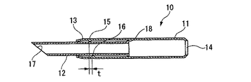
以下、本発明の実施の形態について図面を参照しながら詳細に説明する。まず、本発明の多段ストローの製造装置で製造された多段ストローを図1および図2に示す。本発明の多段ストロー(2段式ストロー)10は、外管(ストローブロック)11と、この外管11の直径よりも小さい径に形成され、その一部が外管11に挿入された内管(ストローブロック)12とから構成されている。
Hereinafter, embodiments of the present invention will be described in detail with reference to the drawings. First, the multistage straw manufactured with the manufacturing apparatus of the multistage straw of this invention is shown in FIG. 1 and FIG. A multistage straw (two-stage straw) 10 of the present invention is formed with an outer tube (straw block) 11 and a diameter smaller than the diameter of the
外管11は、外形が略円筒に形成され、その先端側には外管11の直径を狭めた第1絞り部13が形成されている。また外管11の後端側にも外管11の直径を狭めた第2絞り部14が形成されている。外管11の第2絞り部14側は、多段ストロー10の吸引口を構成する。これら第1、第2絞り部13,14の間で、第1絞り部13寄りには、第1と第2の溝15、16が形成されている。
The
外管11の第1絞り部13寄りに形成される第1溝15は、外管11の周面の半周分をやや越える長さで伸び、外管11の内側方向に突出するように形成されている。また、第2溝16は、第1溝15の形成位置に反対側になるように外管11の周面の半周分をやや越える長さで伸び、外管11の内側方向に突出するように形成されている。半周分をやや超える部分は、円周上では第1溝15と第2溝16とが重複している。重複部の溝の深さは他の部分より浅く、溝の端に行けば行くほど浅くなり最終的には溝の深さはゼロとなる。重複していない部分の溝の深さはほぼ一定である。また、溝の形状は、図2に示すようにストロー先端部側が最も深い形状とすることで、図3Aに示すように、内管12の拡径部18を容易に係止することができるため好ましい。
The
こうした第1溝15と第2溝16との間隔t(図2参照)は、例えば外管の長尺方向に0.2〜2.0mmの範囲で離されて、互いに対面するように外管11の周面の略半周分の長さでそれぞれ伸びるように形成されている。第1溝15と第2溝16との間隔tは、0.2mm未満では、後述するねじ効果が十分発揮できない恐れがあり、2.0mmを超えるとストッパーとしての効果が不足する恐れがある。このような第1溝15と第2溝16とで、後述する内管12の拡径部18の戻りが防止される。
The distance t (see FIG. 2) between the
内管12は、外形が略円筒に形成され、その一端側には先端を尖らせた先鋭部17が形成されている。こうした先鋭部17は、飲料容器のストロー挿入口を塞ぐフィルムなどの薄膜を貫通させる役割りを果たす。また内管12の他端側には、拡径部18が形成されている。内管12の拡径部18は、ラッパ状あるいはラッパ状の先がさらにストレートになっているものなどの形状があるが、本発明における拡径部18は、内管12の周面から外側に張り出すリング状の突条が好ましい。拡径部18のストローの長尺方向の厚みは、例えば0.1〜2.0mmに形成されるのが好ましく、0.2〜1.0mmに形成されるのがより好ましい。内管12の拡径部18をリング状の突条からなるフランジ形状とすることで、多段ストロー10の内管12を回転させながら引伸ばす際に、外管11の第1溝15と第2溝16の端の溝の浅い部分を乗り越えやすくなり、ねじを回転して引き抜くように容易に引伸ばすことが可能となる。拡径部18は、多段ストロー10の延伸状態は図3Aのように係止され、外管11の第1溝15と第2溝16とで縮むことが防止される。
The outer shape of the
以上のような構成の、本発明の多段ストローの作用について説明する。本発明の多段ストロー10の使用時には、外管11から内管12を引き出し、多段ストロー10の全長を長くした状態で使用する。これにより、多段ストロー10を飲料入り飲料容器に挿入した際に飲料を吸引しやすくなる。
The operation of the multistage straw of the present invention having the above configuration will be described. When the
本発明の多段ストロー10では、外管11から内管12を引き出した延伸状態にすると、図3Aに示すように、外管11の内側に突出した第1溝15と内管12の周面から外側に張り出した拡径部18との係合によって、外管11に対して引き出した内管12が係止される。
In the
第1溝15と第2溝16の形状を外ストロー先端部側が最も深い形状とし、第1溝15と第2溝16が次第に浅くなる円周上の共通部を設けることで、溝を有する内管12の戻り防止効果を低下させること無く、引伸ばす際の抵抗を低下させることが可能となり、ねじ効果を高めることが可能となる。ねじ効果は、溝がらせん状に繋がっていないため、ねじと同じ効果は無いが、内ストローを回転させることでねじのような推進力が期待され、内ストローを引っ張りながら回転させることで、内ストローを容易に引き伸ばすことができる効果である。そして、図3Bに示すように、外管11に対して内管12が収納方向に戻ろうとする力が加わって、外管11の内側に突出した第1溝15が撓んでも、第2溝16に拡径部18が当り、外管11内に内管12が戻って収縮されることが阻止される。これにより、多段ストロー10の使用時に、外管11から内管12を引き出してから、飲料容器の挿入口に多段ストロー10を突き刺す際に、外管11に対して内管12が収納方向に戻ろうとする力が加わっても、引き伸ばした多段ストロー10が再び収縮してしまうことがない。図3A、Bから明らかなように、第1溝15と第2溝16とは段になっており、拡径部18が一方の溝を変形させて乗り越える前に、もう一方の溝に接触するため、全周に溝(ストッパー)を設けたのと同程度のストッパー効果となる。
The shape of the
図4は、このような多段ストロー10を備えた飲料製品を示す外観図である。多段ストロー10は、塵埃等から多段ストロー10を保護する包装フィルム21に包まれた状態で、飲料製品22を構成する飲料容器23の側面に、例えば斜めに貼り付けられる。消費者は、飲用時に包装フィルム21の一部を破って多段ストロー10を取り出し、多段ストロー10を引き伸ばしてから飲料容器23の上面に形成された差込口24に多段ストロー10を差し込み、飲料を吸引する。
FIG. 4 is an external view showing a beverage product provided with such a
次に、上述したような本発明の多段ストローを製造するための、本発明の多段ストローの製造装置およびその製造方法を説明する。図5、図6は、本発明の多段ストローの製造装置の要部を示す断面図である。ストッパー部を形成する多段ストロー製造装置31は、図1に示す多段ストロー10の外管11に第1溝15と第2溝16とを形成するものであり、回転可能に形成された略円形の第1の成形円盤32と、この第1の成形円盤32に対して一定の間隔で、図6の左右方向Mにずらした位置に配置される回転可能な略円形の第2の成形円盤33とを備えている。
Next, the multistage straw manufacturing apparatus and method for manufacturing the multistage straw of the present invention as described above will be described. 5 and 6 are cross-sectional views showing the main part of the multistage straw manufacturing apparatus of the present invention. The multistage
第1の成形円盤32には、外管11の外径である直径よりも小さい内径を持つ半円周状の成形刃34が円周上に多数形成されている。同様に、第2の成形円盤33にも外管11の直径よりも小さい内径を持つ半円周状の成形刃35が円周上に多数形成されている。こうした成形刃34、35の内径である直径rは、外管11の直径Rよりも10〜30%小さく形成されるのが好ましい。このように、互いにずれた位置にある外管11の直径よりも小さい内径の成形刃34、35で多段ストロー10の外管11を挟み込むことによって、外管11に第1溝15と第2溝16とがそれぞれ形成される。成形刃34、35は、それぞれのストロー管の円周のおよそ半周分が挟み込まれる部分とそれより外側(図5におけるrを示す線より外周側)はストローが入り易く、また外れやすいように逃げ角が設けてある。これにより、ストローに刻まれる溝は、端から徐々に深いものとなる。また、成形刃34、35は図6に示すようにストロー先端部側を深くすることで、ストロー先端部側が深い溝が得られるため好ましい。
In the
第1の成形円盤32と第2の成形円盤33とは、例えば両成形円盤の中心を通る中心軸に平行、かつ中心軸方向に0.2〜3.0mm隔てて配置することが好ましい。また、第1の成形円盤32と第2の成形円盤33とは常温でもよいが、200℃程度まで加熱可能な加熱装置を備えていてもよい。また、多段ストロー製造装置31は、第1の成形円盤32と第2の成形円盤33との間にストローブロック(外管)を保持して供給する供給装置(図示せず)をさらに備えていることが好ましい。ストローの移動方向は図5に示すように成形円盤の間を水平に移動させる方法や、円周方向に移動させる方法があるが、水平方向に移動させることが、ストローに刻まれる溝が、端から徐々に深いものとなりやすく、さらには、図5で上下方向となる成形円盤の間隔を調整することで、溝の深さを調整することが容易に可能となるため、好ましい。
The
このような多段ストロー製造装置31で多段ストローの外管11に第1溝15と第2溝16とを形成する際には、成形刃34、35の間に外管11をセットしつつ第1の成形円盤32と第2の成形円盤33とを回転させる。この時、第1の成形円盤32と第2の成形円盤33とは加熱されていてもよい。そして、成形刃34、35の間に外管11が挟まれる過程で、第1の成形円盤32の成形刃34が第1溝15を、第2の成形円盤33の成形刃35が第2溝16を、それぞれ外管11に形成する。
When the
本出願人は、本発明の多段ストロー製造装置で製造された多段ストローの特性を検証した。検証に当たって、以下のサンプルを用意した。
(実施例)
1. ポリプロピレン製の外管(外径6.0mm)厚み0.25mmを使用し、図5に示す構造の成形円盤(すり合せ歯車歯先円内径5.0mm、中心軸方向のずれ0.5mm)を使用して、130℃に加熱した。速度は800本/分で行い、円周方向に深さ0.3mmの溝が付与できた。図8A及び図8Bに溝近傍の外管断面図を示す。なお、図8A及び図8Bは、それぞれ図3AのI−I断面図及びII−II断面図である。上溝と下溝との間隔は外管の長尺方向に0.3mmであった。
2.速度1000本/分では、150℃に加熱したところ、深さ0.3mmの溝が付与ができた。
3. ポリプロピレン製の外管(外径5.0mm)厚み0.25mmを使用し、図5に示す構造の歯車(すり合せ歯車歯先円内径5.0mm、中心軸方向のずれ0.5mm)を使用して、130℃に加熱した。速度は800本/分で行い、円周方向に深さ0.25mmの溝が付与できた。上溝と下溝との間隔は外管の長尺方向に0.3mmであった。
The present applicant verified the characteristics of the multistage straw produced by the multistage straw production apparatus of the present invention. The following samples were prepared for verification.
(Example)
1. A polypropylene outer tube (outer diameter 6.0 mm) with a thickness of 0.25 mm is used, and a forming disk having a structure shown in FIG. And heated to 130 ° C. The speed was 800 pieces / minute, and a groove having a depth of 0.3 mm could be provided in the circumferential direction. 8A and 8B are cross-sectional views of the outer tube near the groove. 8A and 8B are a cross-sectional view taken along line II and II-II in FIG. 3A, respectively. The distance between the upper groove and the lower groove was 0.3 mm in the longitudinal direction of the outer tube.
2. At a speed of 1000 lines / minute, when heated to 150 ° C., a groove having a depth of 0.3 mm could be provided.
3. A polypropylene outer tube (outer diameter 5.0 mm) with a thickness of 0.25 mm is used, and a gear having the structure shown in FIG. And heated to 130 ° C. The speed was 800 pieces / minute, and a groove having a depth of 0.25 mm could be provided in the circumferential direction. The distance between the upper groove and the lower groove was 0.3 mm in the longitudinal direction of the outer tube.
(比較例)
1. ポリプロピレン製の外管(外径6.0mm)厚み0.25mmを使用し、平行に深さ0.3mm、長さ4mmの溝からなるストッパー部を有する外管。図9にストッパー部の断面図を示す。
2.ポリプロピレン製の外管(外径6.0mm)厚み0.25mmを使用し、連続した円周上に深さ0.3mmの溝からなるストッパー部を有する外管。図10にストッパー部の断面図を示す。
(Comparative example)
1. An outer tube made of polypropylene (outer diameter 6.0 mm) having a thickness of 0.25 mm and having a stopper portion formed of a groove having a depth of 0.3 mm and a length of 4 mm in parallel. FIG. 9 shows a cross-sectional view of the stopper portion.
2. An outer tube made of polypropylene (outer diameter 6.0 mm) having a thickness of 0.25 mm and having a stopper portion comprising a groove having a depth of 0.3 mm on a continuous circumference. FIG. 10 shows a cross-sectional view of the stopper portion.
以上のような実施例と比較例の2段ストローの外管を用い、戻り抵抗と引き伸ばしやすさを検証した。検証結果を表1に示す。なお、戻り抵抗値の測定方法としては、引き伸ばしたストローを準備し、内ストロー(内管)と外ストロー(外管)を固定し一定速度で間隔が狭くなるように外ストローを移動し、ストッパーを乗り越えるときの最大荷重を読み取った。引き伸ばし抵抗値及び戻り抵抗値測定時の移動速度は100mm/分とした。なお、外ストローの外管が外径6.0mmのときに、用いた内ストローは、外径4.5mm、フランジ形状の拡径部外径5.2mm及び拡径部の内ストロー長尺方向の厚み0.2mmの内ストローである。また、外ストローの外管が外径5.0mmときに、用いた内ストローは、外径3.8mm、フランジ形状の拡径部外径4.4mm及び拡径部の内ストロー長尺方向の厚み0.2mmの内ストローである。 Using the outer tubes of the two-stage straws of the example and the comparative example as described above, the return resistance and the ease of stretching were verified. The verification results are shown in Table 1. The return resistance value is measured by preparing a stretched straw, fixing the inner straw (inner tube) and outer straw (outer tube), moving the outer straw so that the interval is narrowed at a constant speed, and stopping the stopper. The maximum load when overcoming was read. The moving speed when measuring the stretching resistance value and the return resistance value was 100 mm / min. When the outer tube of the outer straw has an outer diameter of 6.0 mm, the inner straw used was an outer diameter of 4.5 mm, a flange-shaped expanded portion outer diameter of 5.2 mm, and the expanded portion of the inner straw in the longitudinal direction. An inner straw having a thickness of 0.2 mm. When the outer tube of the outer straw has an outer diameter of 5.0 mm, the inner straw used is 3.8 mm in outer diameter, 4.4 mm in outer diameter of the flange-shaped expanded portion and the inner straw in the longitudinal direction of the expanded portion. An inner straw having a thickness of 0.2 mm.

表1に示す検証結果によれば、本発明例の多段ストローは、従来の多段ストローと比較して、遜色なく戻り抵抗は大きく保つことができ、かつ、引き伸ばしやすさが向上したことが確認された。 According to the verification results shown in Table 1, it is confirmed that the multistage straw of the present invention example can maintain a large return resistance without being inferior to the conventional multistage straw, and the ease of stretching is improved. It was.
10・・多段ストロー、11・・外管、12・・内管、15・・第1溝、16・・第2溝、31・・多段ストロー製造装置、32・・第1の成形円盤、33・・第2の成形円盤、34,35・・成形刃 10 .... multi-stage straw, 11 .... outer tube, 12 .... inner tube, 15 .... first groove, 16 .... second groove, 31 ... multi-stage straw manufacturing equipment, 32 ... first molding disk, 33 ..Second molding disk, 34, 35
Claims (6)
溝状のストッパー部が形成される前記ストローブロックの直径よりも小さい内径を持つ半円周状の成形刃が多数形成された第1の成形円盤と第2の成形円盤とを、互いに中心軸が平行でかつ中心軸方向に一定間隔でずらして配置し、前記第1の成形円盤の成形刃と前記第2の成形円盤の成形刃とが互いに対向して前記ストローブロックを挟むことにより、前記ストローブロックの周面に、溝を前記ストローブロックの長尺方向に互いに一定間隔を空けて半円周状に対向させて形成することを特徴とする多段ストローの製造装置。 A multi-stage straw manufacturing apparatus comprising a plurality of straw blocks having different diameters, wherein the straw blocks are slidably inserted into each other, and the overall length is expandable and contractible.
The first molding disk and the second molding disk each having a plurality of semicircular molding blades having an inner diameter smaller than the diameter of the straw block in which the groove-shaped stopper portion is formed are mutually connected with the central axes thereof. The straws are arranged parallel to each other at a constant interval in the central axis direction, and the straw blade is sandwiched between the molding blade of the first molding disk and the molding blade of the second molding disk facing each other. An apparatus for producing a multistage straw, wherein grooves are formed on a circumferential surface of the block so as to face each other in a semicircular shape with a predetermined interval in the longitudinal direction of the straw block.
溝状のストッパー部が形成される前記ストローブロックの直径よりも小さい内径を持つ半円周状の成形刃が多数形成された第1の成形円盤と第2の成形円盤とを、互いに中心軸が平行でかつ中心軸方向に一定間隔でずらして配置し、前記第1の成形円盤の成形刃と前記第2の成形円盤の成形刃とが互いに対向して前記ストローブロックを挟むことにより、前記ストローブロックの周面に、溝を前記ストローブロックの長尺方向に互いに一定間隔を空けて半円周状に対向させて形成することを特徴とする多段ストローの製造方法。 It is composed of a plurality of straw blocks having different diameters from each other, these straw blocks are slidably inserted into each other, and a multistage straw manufacturing method in which the overall length can be expanded and contracted,
The first molding disk and the second molding disk each having a plurality of semicircular molding blades having an inner diameter smaller than the diameter of the straw block in which the groove-shaped stopper portion is formed are mutually connected with the central axes thereof. The straws are arranged parallel to each other at a constant interval in the central axis direction, and the straw blade is sandwiched between the molding blade of the first molding disk and the molding blade of the second molding disk facing each other. A method for producing a multistage straw, characterized in that grooves are formed on the circumferential surface of the block so as to face each other in a semicircular shape with a predetermined interval in the longitudinal direction of the straw block.
Priority Applications (1)
| Application Number | Priority Date | Filing Date | Title |
|---|---|---|---|
| JP2004326471A JP4612397B2 (en) | 2004-11-10 | 2004-11-10 | Multistage straw and its forming apparatus and forming method |
Applications Claiming Priority (1)
| Application Number | Priority Date | Filing Date | Title |
|---|---|---|---|
| JP2004326471A JP4612397B2 (en) | 2004-11-10 | 2004-11-10 | Multistage straw and its forming apparatus and forming method |
Publications (2)
| Publication Number | Publication Date |
|---|---|
| JP2006136386A JP2006136386A (en) | 2006-06-01 |
| JP4612397B2 true JP4612397B2 (en) | 2011-01-12 |
Family
ID=36617567
Family Applications (1)
| Application Number | Title | Priority Date | Filing Date |
|---|---|---|---|
| JP2004326471A Expired - Fee Related JP4612397B2 (en) | 2004-11-10 | 2004-11-10 | Multistage straw and its forming apparatus and forming method |
Country Status (1)
| Country | Link |
|---|---|
| JP (1) | JP4612397B2 (en) |
Families Citing this family (1)
| Publication number | Priority date | Publication date | Assignee | Title |
|---|---|---|---|---|
| CN105144687B (en) * | 2013-04-30 | 2019-07-26 | 索尼公司 | Image processing apparatus, image processing method, and computer-readable medium |
Family Cites Families (2)
| Publication number | Priority date | Publication date | Assignee | Title |
|---|---|---|---|---|
| JPH0513545Y2 (en) * | 1985-08-29 | 1993-04-09 | ||
| JP3380207B2 (en) * | 2000-03-23 | 2003-02-24 | 昭和電工プラスチックプロダクツ株式会社 | Multistage straw manufacturing apparatus and manufacturing method |
-
2004
- 2004-11-10 JP JP2004326471A patent/JP4612397B2/en not_active Expired - Fee Related
Also Published As
| Publication number | Publication date |
|---|---|
| JP2006136386A (en) | 2006-06-01 |
Similar Documents
| Publication | Publication Date | Title |
|---|---|---|
| CN105102050B (en) | Blown-moulding for conduit is packed | |
| CN209270582U (en) | Guide sheath and guide | |
| US3194468A (en) | Plastic drinking cups | |
| USD980427S1 (en) | Expandable medical device | |
| WO1997034817A1 (en) | Heat insulating container and method of manufacturing the same | |
| USD625409S1 (en) | Single lumen catheter hub | |
| JP2018011954A (en) | Straw with improved structure | |
| US8506283B1 (en) | Tamale maker | |
| US6685103B2 (en) | Straw tube, and apparatus and method for producing the same | |
| JP4612397B2 (en) | Multistage straw and its forming apparatus and forming method | |
| US12324883B2 (en) | Expandable balloon sheaths | |
| JP3221962U (en) | Wooden hollow pipe molding machine | |
| WO2006036908A2 (en) | Safety straw | |
| JP3380219B2 (en) | Straw tube, manufacturing apparatus and manufacturing method thereof | |
| JP5498235B2 (en) | Beverage can body | |
| JP5713700B2 (en) | Bellows-type telescopic straw | |
| USD1045075S1 (en) | Outer sheath | |
| JP6476429B2 (en) | Plastic food dispensing container | |
| USD885576S1 (en) | Expandable medical device | |
| US20200069095A1 (en) | Edible straw | |
| CN221673140U (en) | Mastoid band, mastoid balloon and mastoid balloon catheter | |
| JP2004001877A (en) | Paper-made beverage container | |
| CN205652577U (en) | Foods bag | |
| JP4573787B2 (en) | Tube container set and method of forming the same | |
| JP3250099B2 (en) | Drinking straw structure |
Legal Events
| Date | Code | Title | Description |
|---|---|---|---|
| A711 | Notification of change in applicant |
Free format text: JAPANESE INTERMEDIATE CODE: A711 Effective date: 20070529 |
|
| A621 | Written request for application examination |
Free format text: JAPANESE INTERMEDIATE CODE: A621 Effective date: 20070912 |
|
| A977 | Report on retrieval |
Free format text: JAPANESE INTERMEDIATE CODE: A971007 Effective date: 20100728 |
|
| TRDD | Decision of grant or rejection written | ||
| A01 | Written decision to grant a patent or to grant a registration (utility model) |
Free format text: JAPANESE INTERMEDIATE CODE: A01 Effective date: 20100921 |
|
| A01 | Written decision to grant a patent or to grant a registration (utility model) |
Free format text: JAPANESE INTERMEDIATE CODE: A01 |
|
| A61 | First payment of annual fees (during grant procedure) |
Free format text: JAPANESE INTERMEDIATE CODE: A61 Effective date: 20101015 |
|
| FPAY | Renewal fee payment (event date is renewal date of database) |
Free format text: PAYMENT UNTIL: 20131022 Year of fee payment: 3 |
|
| R150 | Certificate of patent or registration of utility model |
Ref document number: 4612397 Country of ref document: JP Free format text: JAPANESE INTERMEDIATE CODE: R150 Free format text: JAPANESE INTERMEDIATE CODE: R150 |
|
| R250 | Receipt of annual fees |
Free format text: JAPANESE INTERMEDIATE CODE: R250 |
|
| R250 | Receipt of annual fees |
Free format text: JAPANESE INTERMEDIATE CODE: R250 |
|
| R250 | Receipt of annual fees |
Free format text: JAPANESE INTERMEDIATE CODE: R250 |
|
| R250 | Receipt of annual fees |
Free format text: JAPANESE INTERMEDIATE CODE: R250 |
|
| R250 | Receipt of annual fees |
Free format text: JAPANESE INTERMEDIATE CODE: R250 |
|
| R250 | Receipt of annual fees |
Free format text: JAPANESE INTERMEDIATE CODE: R250 |
|
| S533 | Written request for registration of change of name |
Free format text: JAPANESE INTERMEDIATE CODE: R313533 |
|
| R350 | Written notification of registration of transfer |
Free format text: JAPANESE INTERMEDIATE CODE: R350 |
|
| R250 | Receipt of annual fees |
Free format text: JAPANESE INTERMEDIATE CODE: R250 |
|
| LAPS | Cancellation because of no payment of annual fees |