JP4615575B2 - Keyless entry device - Google Patents
Keyless entry device Download PDFInfo
- Publication number
- JP4615575B2 JP4615575B2 JP2008049261A JP2008049261A JP4615575B2 JP 4615575 B2 JP4615575 B2 JP 4615575B2 JP 2008049261 A JP2008049261 A JP 2008049261A JP 2008049261 A JP2008049261 A JP 2008049261A JP 4615575 B2 JP4615575 B2 JP 4615575B2
- Authority
- JP
- Japan
- Prior art keywords
- vehicle
- handle portion
- keyless entry
- portable device
- vehicle body
- Prior art date
- Legal status (The legal status is an assumption and is not a legal conclusion. Google has not performed a legal analysis and makes no representation as to the accuracy of the status listed.)
- Expired - Fee Related
Links
Images




Classifications
-
- B—PERFORMING OPERATIONS; TRANSPORTING
- B60—VEHICLES IN GENERAL
- B60R—VEHICLES, VEHICLE FITTINGS, OR VEHICLE PARTS, NOT OTHERWISE PROVIDED FOR
- B60R25/00—Fittings or systems for preventing or indicating unauthorised use or theft of vehicles
- B60R25/20—Means to switch the anti-theft system on or off
- B60R25/2027—Means to switch the anti-theft system on or off with data signals passing through the human body
-
- G—PHYSICS
- G07—CHECKING-DEVICES
- G07C—TIME OR ATTENDANCE REGISTERS; REGISTERING OR INDICATING THE WORKING OF MACHINES; GENERATING RANDOM NUMBERS; VOTING OR LOTTERY APPARATUS; ARRANGEMENTS, SYSTEMS OR APPARATUS FOR CHECKING NOT PROVIDED FOR ELSEWHERE
- G07C9/00—Individual registration on entry or exit
- G07C9/00174—Electronically operated locks; Circuits therefor; Nonmechanical keys therefor, e.g. passive or active electrical keys or other data carriers without mechanical keys
- G07C9/00309—Electronically operated locks; Circuits therefor; Nonmechanical keys therefor, e.g. passive or active electrical keys or other data carriers without mechanical keys operated with bidirectional data transmission between data carrier and locks
-
- E—FIXED CONSTRUCTIONS
- E05—LOCKS; KEYS; WINDOW OR DOOR FITTINGS; SAFES
- E05B—LOCKS; ACCESSORIES THEREFOR; HANDCUFFS
- E05B81/00—Power-actuated vehicle locks
- E05B81/54—Electrical circuits
- E05B81/64—Monitoring or sensing, e.g. by using switches or sensors
- E05B81/76—Detection of handle operation; Detection of a user approaching a handle; Electrical switching actions performed by door handles
- E05B81/77—Detection of handle operation; Detection of a user approaching a handle; Electrical switching actions performed by door handles comprising sensors detecting the presence of the hand of a user
-
- G—PHYSICS
- G07—CHECKING-DEVICES
- G07C—TIME OR ATTENDANCE REGISTERS; REGISTERING OR INDICATING THE WORKING OF MACHINES; GENERATING RANDOM NUMBERS; VOTING OR LOTTERY APPARATUS; ARRANGEMENTS, SYSTEMS OR APPARATUS FOR CHECKING NOT PROVIDED FOR ELSEWHERE
- G07C9/00—Individual registration on entry or exit
- G07C9/00174—Electronically operated locks; Circuits therefor; Nonmechanical keys therefor, e.g. passive or active electrical keys or other data carriers without mechanical keys
- G07C2009/00753—Electronically operated locks; Circuits therefor; Nonmechanical keys therefor, e.g. passive or active electrical keys or other data carriers without mechanical keys operated by active electrical keys
- G07C2009/00809—Electronically operated locks; Circuits therefor; Nonmechanical keys therefor, e.g. passive or active electrical keys or other data carriers without mechanical keys operated by active electrical keys with data transmission through the human body
-
- G—PHYSICS
- G07—CHECKING-DEVICES
- G07C—TIME OR ATTENDANCE REGISTERS; REGISTERING OR INDICATING THE WORKING OF MACHINES; GENERATING RANDOM NUMBERS; VOTING OR LOTTERY APPARATUS; ARRANGEMENTS, SYSTEMS OR APPARATUS FOR CHECKING NOT PROVIDED FOR ELSEWHERE
- G07C2209/00—Indexing scheme relating to groups G07C9/00 - G07C9/38
- G07C2209/60—Indexing scheme relating to groups G07C9/00174 - G07C9/00944
- G07C2209/63—Comprising locating means for detecting the position of the data carrier, i.e. within the vehicle or within a certain distance from the vehicle
- G07C2209/65—Comprising locating means for detecting the position of the data carrier, i.e. within the vehicle or within a certain distance from the vehicle using means for sensing the user's hand
Landscapes
- Engineering & Computer Science (AREA)
- Mechanical Engineering (AREA)
- Computer Networks & Wireless Communication (AREA)
- Physics & Mathematics (AREA)
- General Physics & Mathematics (AREA)
- Lock And Its Accessories (AREA)
- Near-Field Transmission Systems (AREA)
Description
本発明は、車両側装置と携帯機との間で通信を行うことによりドアの施錠・解錠等を行うキーレスエントリー装置に関し、特に人体通信を用いて車両側装置と携帯機との間で通信を行うキーレスエントリー装置に関する。 The present invention relates to a keyless entry device that performs locking and unlocking of a door by performing communication between a vehicle-side device and a portable device, and in particular, communication between the vehicle-side device and the portable device using human body communication. It is related with the keyless entry device which performs.
キーレスエントリー装置においては、自動車等の車両に車両側装置を設け、運転者が携帯する携帯機との間で無線通信を行って、認証が成立した場合にドアの施錠・解錠を行うようにしている。このキーレスエントリー装置において、携帯機と車両側装置との間で人体を介した通信を用いるものが、従来提案されている。 In a keyless entry device, a vehicle side device is provided in a vehicle such as an automobile, and wireless communication is performed with a portable device carried by the driver so that the door is locked and unlocked when authentication is established. ing. In this keyless entry device, a device that uses communication via a human body between a portable device and a vehicle-side device has been conventionally proposed.
本願出願人は、人体通信を用いたキーレスエントリー装置として、特願2006−230014に記載される装置を提案している。このキーレスエントリー装置は、車両のドアに設けられるドアハンドルの表面側(外側)と裏面側(内側、車体側)に別々の電極を設け、ドアハンドルが操作される際に、人体の手指を介して通信が行われ、携帯機と車両側装置との間で認証等を行うこととしている。 The present applicant has proposed a device described in Japanese Patent Application No. 2006-230014 as a keyless entry device using human body communication. In this keyless entry device, separate electrodes are provided on the front side (outside) and back side (inside, vehicle body side) of the door handle provided on the door of the vehicle. Communication is performed, and authentication or the like is performed between the portable device and the vehicle-side device.
ドアハンドルの種類としては、フラップ状のハンドル本体を上方に引き起こすものや、同じくフラップ状のハンドル本体を右方向あるいは左方向に引き起こすもの、グリップ状の把手部を握って手前に引くもの等が一般に採用されている。前述の特願2006−230014では、グリップ式の把手部を有したドアハンドルについて適用されるものである。 The types of door handles are generally those that cause the flap-shaped handle body to move upward, those that also cause the flap-shaped handle body to move to the right or left, and those that grip the grip-like handle and pull it forward. It has been adopted. The above-mentioned Japanese Patent Application No. 2006-230014 is applied to a door handle having a grip handle portion.
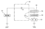
グリップ状の把手部を有するドアハンドルは、ドアを開く際には把手部の内側面に指を差し入れて引くように操作がなされ、ドアを閉じる際には把手部の外側面を手で押すように操作がなされる。このように把手部の操作がなされる際における回路図を図13に示している。なお、この図において破線で表された部分は等価回路であり、実線で表された部分は実際に配線されている部分を示している。 A door handle with a grip-like handle is operated by inserting and pulling a finger into the inner surface of the handle when opening the door, and pushing the outer surface of the handle by hand when closing the door The operation is performed. FIG. 13 shows a circuit diagram when the handle portion is operated as described above. In this figure, the portion indicated by a broken line is an equivalent circuit, and the portion indicated by a solid line indicates a portion that is actually wired.
図13に示すように、操作のために把手部に手が触れて、人体52と把手部54内の車両に設けた車両側電極55とが近接すると、使用者が携帯する携帯機51と車両側電極55との間に人体52を介したC2を有する等価回路が形成される。同時に、車両側電極55と車体53との間にも、人体52を介したC1を有する等価回路が形成される。
As shown in FIG. 13, when a hand touches the handle portion for operation and the
携帯機51から信号を送信した場合、信号は人体52及び車両側電極55を介して車両側装置50に伝送されるが、車両側電極55と車体53との間にもC1を有する等価回路が形成されているため、C1側にも信号が伝送されることとなる。従来の人体通信を用いたキーレスエントリー装置では、電極形状は把手部54の表面側と裏面側がいずれも同等の大きさを有する平板状であるため、特に把手部54の内側面に指を差し入れて引くように操作を行う場合、把手部54の裏面側の電極と車体との距離が近く、かつその間に人体52が存在することとなるために、図13に示すC1が大きくなって、携帯機51からの信号の大半がC1を有する等価回路に伝送される。このため、車両側装置50では充分な大きさの信号を受信することができなくなる。また、車両側装置50から携帯機51に信号を送信した場合においても、同様の問題が生じる。
When a signal is transmitted from the
本発明は上記課題を鑑みてなされたものであり、車両側の電極と車体との間に人体を介して生じる静電容量の影響をできるだけ小さくして、携帯機側と車両側とで効率よく通信を行うことのできるキーレスエントリー装置を提供することを目的とする。 The present invention has been made in view of the above problems, and it is possible to reduce the influence of electrostatic capacitance generated between the vehicle-side electrode and the vehicle body through the human body as much as possible, and efficiently between the portable device side and the vehicle side. An object of the present invention is to provide a keyless entry device capable of performing communication.
上記課題を解決するため、本発明に係るキーレスエントリー装置は、車両に設けられる車両側装置と携帯機との間で通信をなすキーレスエントリー装置において、
前記携帯機は、認証のための信号の通信を行う携帯機制御部と、該携帯機制御部が前記信号によって生成される電界を人体に誘起させる携帯機電極とを有し、
前記車両は、グリップ状の把手部を備えたドアハンドルをドアに有し、前記ドアハンドルの把手部は前記携帯機電極により人体に誘起された前記電界を検出する車両側電極を備え、前記車両には前記車両側電極で検出した電界により信号が入力され、該信号の認証を行う車両側制御部が設けられ、
前記車両側電極は、前記車両の車体面に対向する第1面と、前記車両の車体面に対向し前記第1面より前記車体から遠い位置に配置される第2面と、前記第1面及び第2面と直交し互いに平行な上面及び下面とのうち少なくとも2面を有し、前記第1面以外の面のみからなるか、あるいは前記第1面を有し該第1面は他の面より面積が小さくなるように形成されることを特徴として構成されている。
In order to solve the above problems, a keyless entry device according to the present invention is a keyless entry device that performs communication between a vehicle-side device provided in a vehicle and a portable device.
The portable device includes a portable device control unit that performs communication of a signal for authentication, and a portable device electrode that induces an electric field generated by the signal by the portable device control unit in the human body,
The vehicle has a door handle provided with a grip-like handle portion at a door, and the handle portion of the door handle includes a vehicle-side electrode that detects the electric field induced in a human body by the portable device electrode. Is provided with a vehicle-side control unit that receives a signal from the electric field detected by the vehicle-side electrode and authenticates the signal.
The vehicle-side electrode includes a first surface facing the vehicle body surface of the vehicle, a second surface facing the vehicle body surface of the vehicle and disposed at a position farther from the vehicle body than the first surface, and the first surface. And at least two of an upper surface and a lower surface that are orthogonal to the second surface and parallel to each other, and are composed only of surfaces other than the first surface, or the first surface has another surface. It is configured such that the area is smaller than the surface.
さらに、本発明に係るキーレスエントリー装置は、前記把手部は前記車体に対して連結される支持部を両端部に備え、前記把手部の一端部側の支持部は回転中心部を有し、前記把手部の他端部側の支持部は前記車体に対して外側に引き出し自在に支持され、前記車両側電極の第1面は前記把手部の他端部側に偏って配置されることを特徴として構成されている。 Furthermore, in the keyless entry device according to the present invention, the handle portion includes support portions connected to the vehicle body at both ends, the support portion on one end side of the handle portion has a rotation center portion, The support portion on the other end side of the handle portion is supported so as to be able to be pulled out to the outside with respect to the vehicle body, and the first surface of the vehicle side electrode is arranged to be biased toward the other end portion side of the handle portion. It is configured as.
さらにまた、本発明に係るキーレスエントリー装置は、車両に設けられる車両側装置と携帯機との間で通信をなすキーレスエントリー装置において、
前記携帯機は、認証のための信号の通信を行う携帯機制御部と、該携帯機制御部が前記信号によって生成される電界を人体に誘起させる携帯機電極とを有し、
前記車両は、グリップ状の把手部を備えたドアハンドルをドアに有し、前記ドアハンドルの把手部は前記携帯機電極により人体に誘起された前記電界を検出する車両側電極を備え、前記車両には前記車両側電極で検出した電界により信号が入力され、該信号の認証を行う車両側制御部が設けられ、
前記車両側電極は、前記車両の車体面に対向する第1面と、前記車両の車体面に対向し前記第1面より前記車体から遠い位置に配置される第2面と、前記第1面及び第2面と直交し互いに平行な上面及び下面とのうち少なくとも2面を有し、前記車両側電極は前記第1面以外の面のみからなると共に、前記上面と下面を有し、該上面と下面は前記車体と対向あるいは直交する連結面で連結されることを特徴として構成されている。
Furthermore, the keyless entry device according to the present invention is a keyless entry device that performs communication between a vehicle-side device provided in a vehicle and a portable device.
The portable device includes a portable device control unit that performs communication of a signal for authentication, and a portable device electrode that induces an electric field generated by the signal by the portable device control unit in the human body,
The vehicle includes a door handle provided with a grip-like handle portion at a door, and the handle portion of the door handle includes a vehicle-side electrode that detects the electric field induced in a human body by the portable device electrode. Is provided with a vehicle-side control unit that receives a signal from the electric field detected by the vehicle-side electrode and authenticates the signal.
The vehicle-side electrode includes a first surface facing the vehicle body surface of the vehicle, a second surface facing the vehicle body surface of the vehicle and disposed at a position farther from the vehicle body than the first surface, and the first surface. And at least two surfaces of a top surface and a bottom surface that are orthogonal to the second surface and parallel to each other, and the vehicle-side electrode comprises only a surface other than the first surface, and has the top surface and the bottom surface. And the lower surface are connected by a connecting surface facing or orthogonal to the vehicle body .
そして、本発明に係るキーレスエントリー装置は、前記上面及び下面は前記車体に向かう頂点を有する三角形状に形成されることを特徴として構成されている。 In the keyless entry device according to the present invention, the upper surface and the lower surface are formed in a triangular shape having apexes facing the vehicle body.
また、本発明に係るキーレスエントリー装置は、前記把手部は前記車体に対して連結される支持部を両端部に備え、前記把手部の一端部側の支持部は回転中心部を有し、前記把手部の他端部側の支持部は前記車体に対して外側に引き出し自在に支持され、前記上面及び下面の頂点は前記把手部の他端部側に偏って配置されることを特徴として構成されている。 Further, in the keyless entry device according to the present invention, the handle portion includes support portions connected to the vehicle body at both ends, the support portion on one end side of the handle portion has a rotation center portion, A support portion on the other end side of the handle portion is supported so as to be able to be pulled out to the outside with respect to the vehicle body, and apexes of the upper surface and the lower surface are arranged to be biased toward the other end side of the handle portion. Has been.
さらに、本発明に係るキーレスエントリー装置は、前記車両側電極は前記第2面を有し、該第2面には一端側にスリットが形成されることを特徴として構成されている。 Furthermore, the keyless entry device according to the present invention is configured such that the vehicle-side electrode has the second surface, and a slit is formed on one end side of the second surface.
さらにまた、本発明に係るキーレスエントリー装置は、前記把手部は前記車体に対して連結される支持部を両端部に備え、前記把手部の一端部側の支持部は回転中心部を有し、前記把手部の他端部側の支持部は前記車体に対して外側に引き出し自在に支持され、前記第2面のスリットは前記把手部の一端部側に形成されることを特徴として構成されている。 Furthermore, in the keyless entry device according to the present invention, the handle portion includes support portions connected to the vehicle body at both ends, and the support portion on one end portion side of the handle portion has a rotation center portion, The support portion on the other end side of the handle portion is supported so as to be able to be pulled out to the outside with respect to the vehicle body, and the slit of the second surface is formed on one end portion side of the handle portion. Yes.
本発明に係るキーレスエントリー装置によれば、車両側電極は、車両の車体面に対向する第1面と、車両の車体面に対向し第1面より車体から遠い位置に配置される第2面と、第1面及び第2面と直交し互いに平行な上面及び下面とのうち少なくとも2面を有し、第1面以外の面のみからなるか、あるいは第1面を有し該第1面は他の面より面積が小さくなるように形成されることにより、車両側電極の車体面と対向する面を遠くに位置させ近くに位置する面は車体面と垂直となるように配置する、あるいは車両側電極の車体面と対向する面を小さくすることができ、手指を介して車体との間に生じる静電容量を小さくすることができるので、信号伝送の損失を小さくすることができる。 According to the keyless entry device according to the present invention, the vehicle-side electrode includes the first surface facing the vehicle body surface of the vehicle, and the second surface facing the vehicle body surface of the vehicle and disposed at a position farther from the vehicle body than the first surface. And at least two of an upper surface and a lower surface that are orthogonal to the first surface and the second surface and are parallel to each other, and are composed of only surfaces other than the first surface, or have the first surface and the first surface. Is formed so that the area is smaller than other surfaces, so that the surface facing the vehicle body surface of the vehicle side electrode is located far and the surface located nearby is perpendicular to the vehicle surface, or Since the surface of the vehicle-side electrode facing the vehicle body surface can be reduced and the capacitance generated between the vehicle-side electrode and the vehicle body can be reduced, the loss of signal transmission can be reduced.
また、本発明に係るキーレスエントリー装置によれば、車両側電極は第1面及び第2面を有し、第1面は第2面より短く形成されて面積が小さくなるようにされたことにより、車両側電極の車体面に近い面を小さくするだけで、手指を介して車体との間に生じる静電容量を小さくすることができ、車両側電極を容易に形成することができる。 Further, according to the keyless entry device according to the present invention, the vehicle side electrode has the first surface and the second surface, and the first surface is formed shorter than the second surface so that the area is reduced. Only by reducing the surface of the vehicle-side electrode close to the vehicle body surface, the capacitance generated between the vehicle-side electrode and the vehicle body can be reduced, and the vehicle-side electrode can be easily formed.
さらに、本発明に係るキーレスエントリー装置によれば、車両側電極の第1面は把手部の回転中心部と反対側の端部側に偏って配置されることにより、把手部の手で握られない側の電極面積を少なくして車体と対向する面積を少なくし、握られる側に電極面積が多く配置されることになるため、損失を抑えつつより効率よく信号を伝送することができる。 Furthermore, according to the keyless entry device according to the present invention, the first surface of the vehicle-side electrode is biased to the end portion side opposite to the rotation center portion of the handle portion, so that it is grasped by the hand of the handle portion. Since the electrode area on the non-side is reduced, the area facing the vehicle body is reduced, and the electrode area is increased on the gripped side, so that signals can be transmitted more efficiently while suppressing loss.
さらにまた、本発明に係るキーレスエントリー装置によれば、車両側電極は第1面以外の面のみからなると共に、上面と下面を有し、上面と下面は車体と対向あるいは直交する連結面で連結されることにより、車両側電極を折り曲げ形成により容易に形成することができる。 Furthermore, according to the keyless entry device according to the present invention, the vehicle-side electrode includes only a surface other than the first surface, and has an upper surface and a lower surface, and the upper surface and the lower surface are connected by a connection surface facing or orthogonal to the vehicle body. Thus, the vehicle-side electrode can be easily formed by bending.
そして、本発明に係るキーレスエントリー装置によれば、上面及び下面は車体に向かう頂点を有する三角形状に形成されることにより、車両側電極のうち車体面に近い部分をできるだけ減らして信号伝送の損失をより低減することができる。 According to the keyless entry device according to the present invention, the upper and lower surfaces are formed in a triangular shape having apexes facing the vehicle body, thereby reducing the portion of the vehicle-side electrode close to the vehicle surface as much as possible to reduce signal transmission loss. Can be further reduced.
また、本発明に係るキーレスエントリー装置によれば、上面及び下面の頂点は把手部の回転中心部と反対側の端部側に偏って配置されることにより、把手部の手で握られない側の電極面積を少なくし握られる側に電極面積が多く配置されることになるため、損失を抑えつつより効率よく信号を伝送することができる。 Further, according to the keyless entry device according to the present invention, the apex of the upper surface and the lower surface is arranged so as to be biased toward the end portion side opposite to the rotation center portion of the handle portion, so that the side that cannot be grasped by the hand of the handle portion. Since the electrode area is reduced and the electrode area is increased, the signal can be transmitted more efficiently while suppressing loss.
さらに、本発明に係るキーレスエントリー装置によれば、車両側電極は第2面を有し、第2面には一端側にスリットが形成されることにより、車体と対向する面積を少なくし車両側電極の手指と対向する面を大きく形成できるので、損失低下と伝送効率のバランスを図ることができる。 Furthermore, according to the keyless entry device according to the present invention, the vehicle-side electrode has the second surface, and a slit is formed on one end side of the second surface, thereby reducing an area facing the vehicle body. Since the surface of the electrode facing the finger can be formed large, a balance between loss reduction and transmission efficiency can be achieved.
さらにまた、本発明に係るキーレスエントリー装置によれば、第2面のスリットは把手部の回転中心部側の端部側に形成されることにより、把手部の手で握られない側の電極面積を少なくして車体と対向する面積を少なくし把手部の手で握られる側に電極の面積が多く配置されることになるため、損失を抑えつつより効率よく信号を伝送することができる。 Furthermore, according to the keyless entry device according to the present invention, the slit of the second surface is formed on the end side of the handle portion on the rotation center side, so that the electrode area on the side that cannot be grasped by the hand of the handle portion. As a result, the area facing the vehicle body is reduced and the area of the electrode is increased on the side gripped by the hand of the handle portion, so that signals can be transmitted more efficiently while suppressing loss.
本発明の実施形態について図面に沿って詳細に説明する。図1には、本実施形態におけるキーレスエントリー装置の概要図を示している。この図に示すように、本実施形態におけるキーレスエントリー装置は、車両1に設けられる車両側装置2と、使用者が携帯する携帯機3との間で人体を介して通信を行い、IDの認証を行ってドア1aの施錠、解錠等の動作をなすものである。
Embodiments of the present invention will be described in detail with reference to the drawings. FIG. 1 shows a schematic diagram of a keyless entry device according to this embodiment. As shown in this figure, the keyless entry device according to the present embodiment communicates via a human body between a vehicle-
図2には、携帯機3の斜視図を示している。この図に示すように、携帯機3は全体が薄型の箱状に形成され、側部には電源スイッチ21が設けられている。また、携帯機3の表面には、図中ハッチングで示す領域に携帯機電極22が配置されている。この携帯機電極22と人体とが接触または近接した状態の場合には、携帯機電極22から人体に電界を誘起することができ、この人体に誘起された電界を車両1側で検出することにより、携帯機3は車両側装置2と人体を介した通信を行うことができる。なお、携帯機電極22の配置については図2に示すものには限られず、配置する領域及び大きさは適宜設定することができる。また、携帯機電極22は、表面に露出するように配置してもよいし、人体に電界を誘起できる範囲で携帯機3の表面近傍となる内面側に設けるようにしてもよい。
FIG. 2 shows a perspective view of the
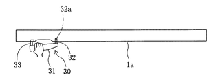
図3は、ドア1aの外側に設けられるドアハンドル30について模式的に示した図である。この図に示すようにドアハンドル30は、ドア1aの外面にグリップ状の形状を有して露出する把手部31と、把手部31の両端部から車体の一部を構成するドア1a側に突出し、ドア1aによって支持される支持部32、33とを有して構成されている。また、把手部31の内部には金属製の車両側電極12が設けられている。
FIG. 3 is a diagram schematically showing the
把手部31の一端部に設けられる支持部32は、ドア1a内において回転中心部32aを中心として回動自在に支持されている。一方、把手部31の他端部に設けられる支持部33は、ドア1aに対して引き出し自在となるように支持されている。図4は、図3の状態からドア1aを開く操作を行った場合の模式図である。ドア1aを開く場合、使用者は把手部31を握って手前側に引くように操作するが、この際、把手部31は、一端側を回転中心とし、他端側がドア1aから離れるように所定角度だけ回動する。したがって、使用者は主に把手部31のうち支持部33が設けられる他端寄りを手で持って操作することとなる。なお、ドア1aを閉じる場合には、使用者は把手部31の外面側を押すように操作する。
The
携帯機3を携帯した使用者がドア1aを車外側から開くため、把手部31を握って引くように操作すると、携帯機3の携帯機電極22によって人体に誘起された電界を、把手部31内の車両側電極12で検出することができ、認証が成立するとドア1aは解錠される。一方で、携帯機3を携帯した使用者がドア1aを閉じるため、把手部31を押すように操作した場合にも、携帯機3の携帯機電極22によって人体に誘起された電界を、把手部31内の車両側電極12で検出することができ、認証が成立してドア1aが閉められるとドア1aを施錠する。なお、この場合において車両側装置2は、ドア1aが施錠されている場合には解錠動作をなし、ドア1aが解錠状態でドア1aが閉められた場合には施錠動作をなす。
When the user carrying the
図5には、本実施形態におけるキーレスエントリー装置のブロック図を示している。この図に示すように、車両1に設けられる車両側装置2は、各種制御を行う車両側制御部10と、車両側制御部10で用いるデータを記憶するメモリ11と、前述した車両側電極12と、ドア1aの施錠及び解錠動作を行う施錠解錠機構13とを有している。また、携帯機3は、所定ビットからなるIDの保管と各種制御と出力する信号の変調を行う携帯機制御部20と電源スイッチ21、携帯機電極22及び電源23を備えており、携帯用電極22には前記IDを示す信号を変調した信号が、常時、繰り返し出力されている。
FIG. 5 shows a block diagram of the keyless entry device in the present embodiment. As shown in this figure, a vehicle-
車両側制御部10は、携帯機3からの信号についての認証を行う判定部10aと、データを一時的に記憶する記憶手段10bと、各電極における電界検出に基づき信号を復調し、これを記憶手段10bに記憶させる入力部10cとを備えている。また、車両側制御部10は車両側電極12からの信号を常時受信可能な状態となっている。
The vehicle-
また、車両側装置2に設けられるメモリ11は、当該車両1用の携帯機3が固有に有するIDを記憶している。車両側制御部10の判定部10aは、記憶手段10bに一時的に記憶された信号に含まれるIDとメモリ11に記憶されたIDとを照合し、これらが一致すれば認証されたものと判定し、一致しなければ認証されなかったものと判定する。
In addition, the
次に、把手部31内に設けられる車両側電極12の構成について詳細に説明する。図6には、車両1と把手部31の模式的な側面図を示している。車両側電極12は把手部31内において、複数の面を有するように形成されるが、車両側電極12には把手部31内で交差する4つの面のうち少なくとも2面が含まれる。図6に示されている4本の破線は、それぞれ各面の位置を表しており、各面は図6の各破線を含む紙面に垂直な面であるものとする。
Next, the structure of the
図6に示すように、4面のうち2面は、車体を構成するドア1aと対向する。そのうちドア1aに近い側の面は第1面40であり、ドア1aから遠い側の面は第2面41であり、これら第1面40と第2面41は互いに対向している。また、残りの2面は第1面40及び第2面41と直交する上面42と下面43であり、これらは互いに平行となる。
As shown in FIG. 6, two of the four surfaces face the door 1a constituting the vehicle body. Of these, the surface near the door 1a is the
車両側電極12は、把手部31が手で持って操作される際に手指と対向する面の面積をできるだけ大きくし、または手指との距離が小さくなるようにすることで、より大きな出力を得ることができる。一方、車体面に対向する面を作らない、または小さくする、あるいはできるだけ遠ざけることで、手指を介して車体面との間に生じる静電容量を小さくし、信号伝送の損失を小さくすることができる。このため、本実施形態の車両側電極12は、図6に示す4面のうち、第1面40以外の面から構成するか、あるいは第1面40を有する場合には他の面よりも第1面40の面積が小さくなるように形成する。具体的には、本実施形態においては以下に示す車両側電極12の第1〜6例のいずれかの態様を採用する。
The vehicle-
図7には、第1例の車両側電極12の斜視図を示している。以下、図7〜12において、車両側電極12を納める把手部31は破線で示されており、またこれらの図では図示しないが図中奥側にドア1aが配置され、右側が支持部32側、左側が支持部33側で人が触れる側となる。図7において第1例の車両側電極12は、図6に示す4面のうち、第1面40及び第2面41を有して構成されている。第1面40及び第2面41は、これらと直交し、かつドア1aの表面とも直交する側面部45によって繋がれており、金属板を折り曲げ形成することにより、車両側電極12が形成される。
FIG. 7 shows a perspective view of the vehicle-
本例では車両側電極12が第1面40を有しているが、第2面41よりは短くなるようにされており、すなわち第1面40は第2面41よりも面積が小さくなるように形成されている。これによって、車両側電極12の車体面と対向する面の面積を比較的小さくすることとなり、手指を介して車体との間に生じる静電容量を小さくすることができるので、信号伝送の損失を小さくすることができる。また、本例の車両側電極12は、第1面40と第2面41の両方を有しているので、ドア1aを開く際に把手部31を握った場合と、ドア1aを閉じるために把手部31を押した場合のいずれにおいても、手指と近接対向するので、確実に通信を行うことができる。
In this example, the vehicle-
また、図7において把手部31は、図中右側の一端側に回転中心部32aを有した支持部32が設けられ、図中左側の他端側にドア1aに対して出没自在な支持部33が設けられる。前述のように、使用者は主に把手部31のうち支持部33が設けられる他端寄りを手で持って操作する。車両側電極12は支持部33が設けられる側において折り返されているので、第2面41より短く形成された第1面40は把手部31のうち支持部33が設けられる側に偏って配置されることとなる。これにより、実際に把手部31が操作される際に手によって握られる位置側に第1面40が配置されることとなり、手指と対向する車両側電極12の面積を充分に確保することができる。
Further, in FIG. 7, the
図8には、第2例の車両側電極12の斜視図を示している。図8において第2例の車両側電極12は、図6に示す4面のうち、第2面41と上面42及び下面43を有して構成されている。すなわち、本例では第1面40を有しないように車両側電極12が形成される。車両側電極12を構成する第2面41と上面42及び下面43は、方形状に形成されており、上面42及び下面43はそれぞれ第2面41の上下端からドア1a側に向かって伸びるように折り曲げ形成されている。
FIG. 8 shows a perspective view of the vehicle-
このように車体面と近接対向する第1面40以外の面のみで車両側電極12を構成することによっても、手指を介して車体との間に生じる静電容量を小さくすることができるので、信号伝送の損失を小さくすることができる。なお、第2面41は車体面から遠いため、手指を介して車体との間に生じる静電容量は小さい。また、上面42及び下面43は、車体面に対して垂直方向の面となる為、手指を介して車体との間に生じる静電容量は小さい。なお、本例の車両側電極12は、第1面40は有していないものの、第2面41と上面42及び下面43を有していることにより、ドア1aと開くときと閉じるときのいずれについても、手指と対向して通信を行うことができる。
Since the vehicle-
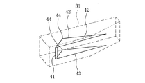
図9には、第3例の車両側電極12の斜視図を示している。第3例の車両側電極12は、第2例の車両側電極12と同様、図6に示す4面のうち、第2面41と上面42及び下面43を有して構成されている。第2面41の構成は第2例と同様であるのに対し、上面42及び下面43は、三角形状をなすように形成されており、それぞれはドア1a側に向かう頂点部44を有している。すなわち、本例の車両側電極12は第2例の車両側電極12に比べて車体面側の領域を切り欠いた形状を有しており、車両側電極12のうち車体面に近い部分をできるだけ減らして信号伝送の損失をより低減することができる。また、本例においても、第2面41と上面42及び下面43を有していることで、ドア1aと開くときと閉じるときのいずれについても、手指と対向して通信を行うことができる。
FIG. 9 shows a perspective view of the vehicle-
頂点部44は、車両側電極12の左右方向において一方側に偏るように配置されている。すなわち、上面42及び下面43を構成する三辺のうち、第2面41と接する一辺を除いた残りの二辺は、一方側が短く他方側が長くなるように形成されている。図9においても回転中心部32aを有した支持部32は図中右側に配置されるので、使用者は主に把手部31のうち支持部33が設けられる図中左寄りを手で持って操作する。車両側電極12は支持部33が設けられる側に頂点部44が偏るように上面42及び下面43が形成されているので、手指と対向する車両側電極12の面積を充分に確保することができる。
The
図10には、第4例の車両側電極12の斜視図を示している。本例の車両側電極12の構成は、図9に示す第3例の車両側電極12と概ね同様であり、異なる点は、第2面41に一端部から左右方向中間位置に渡ってスリット46が形成されていることである。本例の車両側電極12は、このように第2面41にスリット46が形成されていることにより、車体面と対向する第2面41の面積を小さくすることとなるので、手指を介して車体との間に生じる静電容量をより小さくし、信号伝送の損失をさらに小さくすることができる。スリット46を大きくするほど、信号伝送の損失は小さくすることができるが、人体と対向する車両側電極12の面積も小さくなるので、スリット46の大きさを適切に設定することで、車両側電極12で検出する信号強度と信号伝送の損失とのバランスを図ることができる。
FIG. 10 shows a perspective view of the vehicle-
また、スリット46は把手部31において回転中心部32aを有した支持部32が設けられる側に形成され、第2面41は支持部33が設けられる図中左側に偏って配置される。前述のように、使用者は主に把手部31のうち支持部33が設けられる図中左寄りの部分を手で握って操作するので、第2面41が偏って配置されていることで、手指と対向する車両側電極12の面積を充分に確保することができる。
In addition, the
図11には、第5例の車両側電極12の斜視図を示している。本例において車両側電極12は、図6に示す4面のうち、上面42及び下面43を有して構成されており、第1面40及び第2面41は有していない。上面42と下面43は、これらと直交し、かつドア1aの表面とも直交する側面部45によって繋がれており、金属板を折り曲げ形成することにより、車両側電極12が形成される。本例の車両側電極12によれば、第1面40及び第2面41を有しないことにより、ドア1aを開くとき及び閉じるときにおいて、手指と対向する面積はやや小さくなるものの、車体面と対向する面がないので、手指を介して車体との間に生じる静電容量をより小さくし、信号伝送の損失を小さくすることができる。
FIG. 11 shows a perspective view of the vehicle-
図12には、第6例の車両側電極12の斜視図を示している。本例の車両側電極12は、上面42及び下面43が三角形状に形成され、第2面41がごく幅細に形成されている。上面42及び下面43の頂点部44は、第3例の車両側電極12の場合と同様、支持部33が設けられる側に頂点部44が偏るように上面42及び下面43が形成されているので、手指と対向する車両側電極12の面積を充分に確保することができる。
FIG. 12 shows a perspective view of the vehicle-
以上、本発明の実施形態について説明したが、本発明の適用は本実施形態に限られるものではなく、その技術的思想の範囲内において様々に適用されうるものである。例えば、本実施形態では第1面40と第2面41、上面42及び下面43は図6に示すように把手部31内で交わることとし、車両側電極12は把手部31内に納まるようにしているが、第1面40と第2面41、上面42及び下面43のいずれか1面あるいは複数面が把手部31の表面と重なるようにして、車両側電極12が把手部31の表面に露出するようにしてもよい。
Although the embodiment of the present invention has been described above, the application of the present invention is not limited to this embodiment, and can be variously applied within the scope of the technical idea. For example, in the present embodiment, the
1 車両
1a ドア
2 車両側装置
3 携帯機
10 車両側制御部
11 メモリ
12 車両側電極
20 携帯機制御部
30 ドアハンドル
31 把手部
32 支持部
32a 回転中心部
33 支持部
40 第1面
41 第2面
42 上面
43 下面
44 頂点部
45 側面部
46 スリット
DESCRIPTION OF
Claims (7)
前記携帯機は、認証のための信号の通信を行う携帯機制御部と、該携帯機制御部が前記信号によって生成される電界を人体に誘起させる携帯機電極とを有し、
前記車両は、グリップ状の把手部を備えたドアハンドルをドアに有し、前記ドアハンドルの把手部は前記携帯機電極により人体に誘起された前記電界を検出する車両側電極を備え、前記車両には前記車両側電極で検出した電界により信号が入力され、該信号の認証を行う車両側制御部が設けられ、
前記車両側電極は、前記車両の車体面に対向する第1面と、前記車両の車体面に対向し前記第1面より前記車体から遠い位置に配置される第2面と、前記第1面及び第2面と直交し互いに平行な上面及び下面とのうち少なくとも第1面及び第2面を有し、前記第1面は前記第2面より面積が小さくなるように形成されることを特徴とするキーレスエントリー装置。 In a keyless entry device that communicates between a vehicle-side device provided in a vehicle and a portable device,
The portable device includes a portable device control unit that performs communication of a signal for authentication, and a portable device electrode that induces an electric field generated by the signal by the portable device control unit in the human body,
The vehicle has a door handle provided with a grip-like handle portion at a door, and the handle portion of the door handle includes a vehicle-side electrode that detects the electric field induced in a human body by the portable device electrode. Is provided with a vehicle-side control unit that receives a signal from the electric field detected by the vehicle-side electrode and authenticates the signal.
The vehicle-side electrode includes a first surface facing the vehicle body surface of the vehicle, a second surface facing the vehicle body surface of the vehicle and disposed at a position farther from the vehicle body than the first surface, and the first surface. And having at least a first surface and a second surface among an upper surface and a lower surface orthogonal to the second surface and parallel to each other, wherein the first surface is formed to have a smaller area than the second surface. Keyless entry device.
前記携帯機は、認証のための信号の通信を行う携帯機制御部と、該携帯機制御部が前記信号によって生成される電界を人体に誘起させる携帯機電極とを有し、
前記車両は、グリップ状の把手部を備えたドアハンドルをドアに有し、前記ドアハンドルの把手部は前記携帯機電極により人体に誘起された前記電界を検出する車両側電極を備え、前記車両には前記車両側電極で検出した電界により信号が入力され、該信号の認証を行う車両側制御部が設けられ、
前記車両側電極は、前記車両の車体面に対向する第1面と、前記車両の車体面に対向し前記第1面より前記車体から遠い位置に配置される第2面と、前記第1面及び第2面と直交し互いに平行な上面及び下面とのうち少なくとも2面を有し、前記車両側電極は前記第1面以外の面のみからなると共に、前記上面と下面を有し、該上面と下面は前記車体と対向あるいは直交する連結面で連結されることを特徴とするキーレスエントリー装置。 In a keyless entry device that communicates between a vehicle-side device provided in a vehicle and a portable device,
The portable device includes a portable device control unit that performs communication of a signal for authentication, and a portable device electrode that induces an electric field generated by the signal by the portable device control unit in the human body,
The vehicle has a door handle provided with a grip-like handle portion at a door, and the handle portion of the door handle includes a vehicle-side electrode that detects the electric field induced in a human body by the portable device electrode. Is provided with a vehicle-side control unit that receives a signal from the electric field detected by the vehicle-side electrode and authenticates the signal.
The vehicle-side electrode includes a first surface facing the vehicle body surface of the vehicle, a second surface facing the vehicle body surface of the vehicle and disposed at a position farther from the vehicle body than the first surface, and the first surface. And at least two surfaces of a top surface and a bottom surface that are orthogonal to the second surface and parallel to each other, and the vehicle-side electrode comprises only a surface other than the first surface, and has the top surface and the bottom surface. The keyless entry device is characterized in that the lower surface and the lower surface are connected to each other by a connecting surface facing or orthogonal to the vehicle body .
Priority Applications (3)
| Application Number | Priority Date | Filing Date | Title |
|---|---|---|---|
| JP2008049261A JP4615575B2 (en) | 2008-02-29 | 2008-02-29 | Keyless entry device |
| EP20090000867 EP2096008A1 (en) | 2008-02-29 | 2009-01-22 | Keyless entry device |
| US12/363,962 US20090219134A1 (en) | 2008-02-29 | 2009-02-02 | Keyless entry device |
Applications Claiming Priority (1)
| Application Number | Priority Date | Filing Date | Title |
|---|---|---|---|
| JP2008049261A JP4615575B2 (en) | 2008-02-29 | 2008-02-29 | Keyless entry device |
Publications (2)
| Publication Number | Publication Date |
|---|---|
| JP2009203759A JP2009203759A (en) | 2009-09-10 |
| JP4615575B2 true JP4615575B2 (en) | 2011-01-19 |
Family
ID=40682407
Family Applications (1)
| Application Number | Title | Priority Date | Filing Date |
|---|---|---|---|
| JP2008049261A Expired - Fee Related JP4615575B2 (en) | 2008-02-29 | 2008-02-29 | Keyless entry device |
Country Status (3)
| Country | Link |
|---|---|
| US (1) | US20090219134A1 (en) |
| EP (1) | EP2096008A1 (en) |
| JP (1) | JP4615575B2 (en) |
Families Citing this family (20)
| Publication number | Priority date | Publication date | Assignee | Title |
|---|---|---|---|---|
| US11726651B2 (en) | 2009-07-02 | 2023-08-15 | Uusi, Llc | Vehicle occupant detection system |
| US9046967B2 (en) | 2009-07-02 | 2015-06-02 | Uusi, Llc | Vehicle accessory control interface having capactive touch switches |
| US10592092B2 (en) | 2009-07-02 | 2020-03-17 | Uusi, Llc. | User interface with proximity detection for object tracking |
| US11216174B2 (en) | 2009-07-02 | 2022-01-04 | Uusi, Llc | User interface with proximity detection for object tracking |
| US12141432B2 (en) | 2009-07-02 | 2024-11-12 | Uusi, Llc | Vehicle occupant detection system |
| US9199608B2 (en) * | 2009-08-21 | 2015-12-01 | Uusi, Llc | Keyless entry assembly having capacitance sensor operative for detecting objects |
| US11634937B2 (en) | 2009-08-21 | 2023-04-25 | Uusi, Llc | Vehicle assembly having a capacitive sensor |
| US9051769B2 (en) | 2009-08-21 | 2015-06-09 | Uusi, Llc | Vehicle assembly having a capacitive sensor |
| US12320180B2 (en) | 2009-08-21 | 2025-06-03 | Uusi, Llc | Vehicle assembly having a capacitive sensor |
| US9845629B2 (en) | 2009-08-21 | 2017-12-19 | Uusi, Llc | Vehicle keyless entry assembly having capacitance sensor operative for detecting objects |
| US10954709B2 (en) | 2009-08-21 | 2021-03-23 | Uusi, Llc | Vehicle assembly having a capacitive sensor |
| US9705494B2 (en) * | 2009-08-21 | 2017-07-11 | Uusi, Llc | Vehicle assemblies having fascia panels with capacitance sensors operative for detecting proximal objects |
| US10017977B2 (en) * | 2009-08-21 | 2018-07-10 | Uusi, Llc | Keyless entry assembly having capacitance sensor operative for detecting objects |
| US9575481B2 (en) * | 2009-08-21 | 2017-02-21 | Uusi, Llc | Fascia panel assembly having capacitance sensor operative for detecting objects |
| KR101369777B1 (en) * | 2009-12-22 | 2014-03-06 | 한국전자통신연구원 | Telematics system using human body communication, portable device having function of telematics using human body communication and method for providing telematics service using human body communication |
| US8755949B2 (en) | 2009-12-22 | 2014-06-17 | Electronics And Telecommunications Research Institute | Telematics system using human body communication, portable device having telematics function using human body communication, and method for providing telematics service using human body communication |
| US9356960B2 (en) * | 2011-11-07 | 2016-05-31 | Atmel Corporation | Securing radio-frequency identification systems |
| JP2016142046A (en) * | 2015-02-02 | 2016-08-08 | アイシン精機株式会社 | Opening and closing body opening and closing device |
| JP6915481B2 (en) | 2017-09-27 | 2021-08-04 | トヨタ自動車株式会社 | Vehicle control system |
| USD1073985S1 (en) | 2022-10-18 | 2025-05-06 | Uusi, Llc | Sensor weather seal |
Family Cites Families (10)
| Publication number | Priority date | Publication date | Assignee | Title |
|---|---|---|---|---|
| JP2002525702A (en) * | 1998-09-14 | 2002-08-13 | コーニンクレッカ フィリップス エレクトロニクス エヌ ヴィ | Electronic communication system |
| JP3566943B2 (en) * | 2001-07-02 | 2004-09-15 | アイシン精機株式会社 | Vehicle door handle |
| US7543755B2 (en) * | 2001-12-28 | 2009-06-09 | Panasonic Electric Works Co., Ltd. | Electronic key, electronic locking apparatus, electronic security system, and key administering server |
| JP2004346703A (en) * | 2003-05-26 | 2004-12-09 | Aisin Seiki Co Ltd | Antenna element with sensor, door handle device |
| JP4303136B2 (en) * | 2004-01-13 | 2009-07-29 | 株式会社東海理化電機製作所 | Communication device, portable device, and communication system |
| JP4041090B2 (en) * | 2004-04-06 | 2008-01-30 | 本田技研工業株式会社 | Remote locking / unlocking control device for vehicle |
| JP4754972B2 (en) * | 2006-01-19 | 2011-08-24 | 株式会社ユーシン | Door handle device |
| AT503301B1 (en) | 2006-05-04 | 2007-09-15 | Evva Werke | Access control device, has lock with blocking element, actuation element, electronic key, electric circuit with receiving unit for reception of identification data from key, and evaluation circuit for determining access authorization |
| JP2008050892A (en) * | 2006-08-28 | 2008-03-06 | Alps Electric Co Ltd | Keyless entry device |
| US7665776B2 (en) * | 2007-03-07 | 2010-02-23 | Gm Global Technology Operations, Inc. | Handle for vehicle door |
-
2008
- 2008-02-29 JP JP2008049261A patent/JP4615575B2/en not_active Expired - Fee Related
-
2009
- 2009-01-22 EP EP20090000867 patent/EP2096008A1/en not_active Withdrawn
- 2009-02-02 US US12/363,962 patent/US20090219134A1/en not_active Abandoned
Also Published As
| Publication number | Publication date |
|---|---|
| JP2009203759A (en) | 2009-09-10 |
| US20090219134A1 (en) | 2009-09-03 |
| EP2096008A1 (en) | 2009-09-02 |
Similar Documents
| Publication | Publication Date | Title |
|---|---|---|
| JP4615575B2 (en) | Keyless entry device | |
| CN105523009B (en) | Standby key for being integrated into mobile device shell | |
| JP2016142045A (en) | Opening and closing body opening and closing device | |
| JP2010264847A (en) | Electric vehicle | |
| JP2008050892A (en) | Keyless entry device | |
| JP4346384B2 (en) | Fuel tank cap locking device | |
| JP2012061540A (en) | Electric hand tool | |
| JP6217562B2 (en) | In-vehicle USB terminal device | |
| JP4970143B2 (en) | Door opener | |
| JP4694991B2 (en) | Mechanical key and unlocking key | |
| KR102382031B1 (en) | Handle device | |
| CN107804582A (en) | Cold insulated cabinet | |
| ES2310535T3 (en) | DOOR HANDLE WHICH IS FOR A VEHICLE CAR AND WITH A TOUCH SENSOR TO OPERATE WITH A HANDS-FREE ACCESS SYSTEM. | |
| JP2009133158A (en) | Door locking device | |
| JP2007319536A (en) | Game machine | |
| JP2010090635A (en) | Keyless entry device | |
| JP6882028B2 (en) | Smart entry system and its control method | |
| JP6212824B2 (en) | Outdoor handle device | |
| JP5796958B2 (en) | Fish scissors | |
| JP2012102535A (en) | Portable device | |
| JP4919914B2 (en) | Remote control device | |
| JP2011106204A (en) | Door switch device and door device using the same | |
| JP2017160645A (en) | Electric lock device | |
| JP2011001711A (en) | Keyless entry system | |
| JP3144694U (en) | Retaining material such as keys |
Legal Events
| Date | Code | Title | Description |
|---|---|---|---|
| A977 | Report on retrieval |
Free format text: JAPANESE INTERMEDIATE CODE: A971007 Effective date: 20091221 |
|
| A131 | Notification of reasons for refusal |
Free format text: JAPANESE INTERMEDIATE CODE: A131 Effective date: 20100105 |
|
| A521 | Request for written amendment filed |
Free format text: JAPANESE INTERMEDIATE CODE: A523 Effective date: 20100224 |
|
| TRDD | Decision of grant or rejection written | ||
| A01 | Written decision to grant a patent or to grant a registration (utility model) |
Free format text: JAPANESE INTERMEDIATE CODE: A01 Effective date: 20101012 |
|
| A01 | Written decision to grant a patent or to grant a registration (utility model) |
Free format text: JAPANESE INTERMEDIATE CODE: A01 |
|
| A61 | First payment of annual fees (during grant procedure) |
Free format text: JAPANESE INTERMEDIATE CODE: A61 Effective date: 20101020 |
|
| R150 | Certificate of patent or registration of utility model |
Free format text: JAPANESE INTERMEDIATE CODE: R150 |
|
| FPAY | Renewal fee payment (event date is renewal date of database) |
Free format text: PAYMENT UNTIL: 20131029 Year of fee payment: 3 |
|
| LAPS | Cancellation because of no payment of annual fees |