JP4636112B2 - Spare tire storage structure for vehicle - Google Patents
Spare tire storage structure for vehicle Download PDFInfo
- Publication number
- JP4636112B2 JP4636112B2 JP2008110685A JP2008110685A JP4636112B2 JP 4636112 B2 JP4636112 B2 JP 4636112B2 JP 2008110685 A JP2008110685 A JP 2008110685A JP 2008110685 A JP2008110685 A JP 2008110685A JP 4636112 B2 JP4636112 B2 JP 4636112B2
- Authority
- JP
- Japan
- Prior art keywords
- spare tire
- vehicle
- cable
- storage structure
- winding
- Prior art date
- Legal status (The legal status is an assumption and is not a legal conclusion. Google has not performed a legal analysis and makes no representation as to the accuracy of the status listed.)
- Expired - Fee Related
Links
Images




Landscapes
- Body Structure For Vehicles (AREA)
Description
本発明は、車両のスペアタイヤ格納構造に関するものであって、とくに運転時のみならず車両の生産時ないしは組み立て時においてもスペアタイヤを容易に格納し又は脱離させることができるようにした車両のスペアタイヤ格納構造に関するものである。 The present invention relates to a vehicle spare tire storage structure, and more particularly to a vehicle in which a spare tire can be easily stored or removed not only during operation but also during production or assembly of the vehicle. This relates to a spare tire storage structure.
一般に、トランクルームを備えていないタイプの車両、例えばライトバン、ステーションワゴンあるいはトラック等においては、スペアタイヤを車室内に配置するのは好ましくないので(例えば、パンク時には汚れたタイヤを車室内に持ち込まなければならない)、スペアタイヤはフロアパネルの下側の所定の格納位置に格納(保持)されるようになっている。このようにフロアパネルの下側にスペアタイヤを格納するようにした車両では、普通、先端部に係合部材を備えたケーブル(ないしはチェーン)と、車体側に固定され該ケーブルを巻き取り又は解き放つことができるウインチとを設け、係合部材をスペアタイヤと係合させた状態でケーブルを巻き取ることによりスペアタイヤを格納位置に格納し、ケーブルを解き放つことにより該スペアタイヤを格納位置から脱離させるようにしている(例えば、特許文献1参照)。 Generally, in a type of vehicle that does not have a trunk room, such as a light van, a station wagon, or a truck, it is not preferable to place a spare tire in the passenger compartment (for example, a dirty tire must be brought into the passenger compartment when puncturing). The spare tire is stored (held) in a predetermined storage position below the floor panel. In a vehicle in which a spare tire is stored in the lower side of the floor panel as described above, a cable (or a chain) having an engagement member at the front end portion and a cable fixed to the vehicle body side and the cable is wound or released. A winch is provided, and the cable is wound in a state where the engaging member is engaged with the spare tire to store the spare tire in the storage position, and the cable is released to remove the spare tire from the storage position. (For example, refer to Patent Document 1).
そして、フロアパネルの下側にスペアタイヤを格納するようにした従来の車両のスペアタイヤ格納構造では、ウインチの巻き取り又解き放ち操作を行うための操作部は、操作が容易なことから、一般にフロアパネルの上面に配置されている。すなわち、操作部がフロアパネルの下面に配置された場合は、パンク時等においてスペアタイヤを格納位置から脱離させる際、あるいはスペアタイヤ又はタイヤを格納位置に格納する際には、運転者は車体の下側に潜り込まなければならないからである。
ところで、車両の生産ないしは組み立てにおいては、いずれかの工程でスペアタイヤを車両に格納しなければならない。そして、車両の生産ラインないしは組み立てラインにおいては、大部分の工程で車両がハンガに支持された状態で搬送され、ハンガに支持された状態の車両に対して種々の作業ないしは加工が施されることになる。 By the way, in production or assembly of a vehicle, a spare tire must be stored in the vehicle in any of the processes. In the production line or assembly line of a vehicle, the vehicle is transported in a state supported by a hanger in most processes, and various operations or processing are performed on the vehicle supported by the hanger. become.
このため、車両へのスペアタイヤの格納作業は、しばしばハンガに支持された車両に対して行われるが、一般にハンガに支持された車両は比較的高い位置にある(図8参照)。このため、作業者は、スペアタイヤを車両に格納する際に、床面に自然に立った状態で、フロアパネルの上面に配置されたウインチの操作部を操作するのは困難であるといった問題がある。 For this reason, the operation of storing the spare tire in the vehicle is often performed on the vehicle supported by the hanger, but the vehicle supported by the hanger is generally at a relatively high position (see FIG. 8). For this reason, when storing the spare tire in the vehicle, it is difficult for the operator to operate the operation part of the winch arranged on the upper surface of the floor panel while standing on the floor surface. is there.
そこで、従来の車両の生産ラインでは、作業者は、スペアタイヤを車両に格納する際に、ウインチの操作部を操作するための格別の作業装置に乗って作業を行うようにしているが、車両の生産ラインにかかる作業装置を設けると、生産ラインが複雑化するといった問題がある。また、作業者はスペアタイヤを格納する際に作業装置に乗り降りしなければならないので、該作業が繁雑化するといった問題がある。 Therefore, in the conventional vehicle production line, when the spare tire is stored in the vehicle, the worker rides on a special working device for operating the operation unit of the winch. If the working device for the production line is provided, there is a problem that the production line becomes complicated. Further, since the worker has to get on and off the working device when storing the spare tire, there is a problem that the work becomes complicated.
本発明は、上記従来の問題を解決するためになされたものであって、通常の運転時には運転者がスペアタイヤを容易に格納し又は脱離させることができるとともに、車両の生産時ないしは組み立て時には、作業者が格別の作業装置を用いることなくスペアタイヤを車両に容易に格納することができる手段を提供することを解決すべき課題とする。 The present invention has been made to solve the above-described conventional problems, and during normal driving, the driver can easily store or remove the spare tire, and at the time of production or assembly of the vehicle. It is an object of the present invention to provide a means by which an operator can easily store a spare tire in a vehicle without using a special working device.
上記の課題を解決するためになされた本発明にかかる車両のスペアタイヤ格納構造は、(a)車両のフロアパネルの下面側に、略水平な状態でスペアタイヤを保持するようになっている車両のスペアタイヤ格納構造であって、(b)スペアタイヤと係合する係合部材を先端部に備え、フロアパネルより下側において水平方向に関して係合部材の近傍に設けられたスペアタイヤ取付部から垂下する巻き上げケーブルと、(c)車両側に取り付けられ、略水平状態に設置され巻き上げケーブルが巻かれる回転可能なホイールと、鉛直方向に伸びホイールを回転駆動するドライブ軸とを備え、係合部材をスペアタイヤと係合させた状態で、巻き上げケーブルを巻き取り又は解き放つことによりスペアタイヤを格納し又は脱離させるケーブル巻き取り部(ウインチ)とが設けられていて、(d)ケーブル巻き取り部が、フロアパネルより上側の車室側からと、フロアパネルより下方の車外側とから巻き取り又は解き放ち操作が可能となるように、車両後部でフロアパネルの下方に配置され、(e)ドライブ軸は、上部がフロアパネルより上方に位置する上側操作部と、下方に形成された下側操作部とを備え、(f)スペアタイヤ取付部に、係合部材が上方位置にあるときに該係合部材の直ぐ上方に位置し巻き上げケーブルの伸びる方向を水平方向から下方に変えるケーブルガイドが設けられ、(g)ケーブル巻き取り部は、スペアタイヤ取付部より後方に位置する一方、スペアタイヤ取付部より後方に設けられ車幅方向に伸びる最後方メンバより前方に離間してホイール部がケーブルガイドと略同じ高さに位置するように配置され、(h)ケーブル巻き取り部の下側操作部は、最後方メンバの下面より上方に位置することを特徴とするものである。
なお、高さ方向の荷室空間を大きくとるために、ケーブル巻き取り部(ウインチ)は巻き上げケーブルが水平方向に出入りするようにレイアウトするのが好ましい。
本発明にかかる車両のスペアタイヤ格納構造においては、最後方メンバは最後方クロスメンバであり、ケーブル巻き取り部は最後方クロスメンバに固定された支持ブラケットに取り付けられているのが好ましい。
本発明にかかる車両のスペアタイヤ格納構造においては、支持ブラケットは、車両の2つのクロスメンバ間に設けられているのが好ましい。
本発明にかかる車両のスペアタイヤ格納構造においては、ケーブル巻き取り部は、スペアタイヤ取付部の斜め後方に設置されていてもよい。
本発明にかかる車両のスペアタイヤ格納構造においては、巻き上げケーブルは、支持ブラケットが伸びる方向に沿って伸びていてもよい。
本発明にかかる車両のスペアタイヤ格納構造においては、最後方メンバより前方に位置するクロスメンバを備えていて、スペアタイヤ取付部は、クロスメンバの近傍に設置されているのも好ましい。
本発明にかかる車両のスペアタイヤ格納構造においては、ケーブル巻き取り部は、最後方メンバより前方の位置に設置されていてもよい。
Spare tire storage structure for a vehicle according to the present invention made in order to solve the aforementioned problem, is adapted to hold a spare tire (a) on the lower surface of the vehicle full Roapane Le, substantially horizontal state A spare tire storage structure for a vehicle, wherein (b) an engagement member that engages with the spare tire is provided at the tip , and a spare tire mounting portion that is provided in the vicinity of the engagement member in the horizontal direction below the floor panel a cable hoist you depending from, attached to (c) vehicle, comprising a rotatable wheel which is substantially hoist is placed in a horizontal position the cable is wound, a drive shaft for rotating the wheel extends in a vertical direction, the engagement the engagement member in a state in which the spare tire and engaged, hoisting cable winding for storing a spare tire or eliminated by winding or unleashing cable Optionally (winch) are provided, (d) the cable winding part, from the cabin side of the upper side of the floor panel, winding from the vehicle exterior side below the floor panel or unlocks can be operated with Do so that (E) the drive shaft includes an upper operation portion whose upper portion is located above the floor panel and a lower operation portion formed below, (f) The spare tire mounting portion is provided with a cable guide that is located immediately above the engaging member when the engaging member is in the upper position and changes the extending direction of the hoisting cable from the horizontal direction to the lower direction. (G) Cable winding The part is located rearward of the spare tire mounting part, while the wheel part is provided with a cable guide separated from the rearmost member provided rearward of the spare tire mounting part and extending in the vehicle width direction. It is arranged to be substantially located at the same height, the lower operating unit of the (h) cable winding unit and is characterized that you located above the lower surface of the rearmost member.
In order to make the luggage space in the height direction large, it is preferable that the cable winding portion (winch) is laid out so that the winding cable enters and exits in the horizontal direction.
In the spare tire storage structure for a vehicle according to the present invention, the rearmost member is preferably the rearmost cross member, and the cable winding portion is preferably attached to a support bracket fixed to the rearmost cross member.
In the spare tire storage structure for a vehicle according to the present invention, the support bracket is preferably provided between the two cross members of the vehicle.
In the spare tire storage structure for a vehicle according to the present invention, the cable winding portion may be installed obliquely behind the spare tire mounting portion.
In the spare tire storage structure for a vehicle according to the present invention, the winding cable may extend along the direction in which the support bracket extends.
The spare tire storage structure for a vehicle according to the present invention preferably includes a cross member positioned in front of the rearmost member, and the spare tire mounting portion is installed in the vicinity of the cross member.
In the spare tire storage structure for a vehicle according to the present invention, the cable winding portion may be installed at a position ahead of the rearmost member.
この車両のスペアタイヤの格納構造によれば、通常の運転時には、運転者は、車室側からケーブル巻き取り部を操作することにより、スペアタイヤを容易に車両に格納し、又は車両から脱離させることができる。また、該車両の生産時ないしは組み立て時には、作業者は、フロアパネルの下側からケーブル巻き取り部を操作することにより、格別の作業装置を用いることなく、床面(足場)に立った自然な姿勢でスペアタイヤを車両に容易に格納することができる。なお、ケーブル巻き取り部の各操作部が、回転操作によりケーブルを巻き取り又は解き放つようになっている場合、車室側から操作部を回転させるときと、フロアパネルの下側から操作部を回転させるときとでは回転方向は逆向きとなる。
According to the storage structure of the spare tire of the vehicle, during normal driving, the driver can easily store or remove the spare tire from the vehicle by operating the cable winding unit from the passenger compartment side. Can be made. Further, at the time of production or assembly of the vehicle, the operator operates the cable winding portion from the lower side of the floor panel , so that a natural standing on the floor surface (scaffold) without using a special work device. The spare tire can be easily stored in the vehicle in the posture. In addition, when each operation part of the cable winding part is designed to wind up or release the cable by rotating operation, the operation part is rotated from the lower side of the floor panel when rotating the operation part from the passenger compartment side. When rotating, the rotation direction is opposite.
以下、本発明の実施の形態を具体的に説明する。
図1と図2とに示すように、本発明にかかるスペアタイヤ格納構造を備えた2ボックスタイプ(トランクルームを備えていない)の車両1の下部には、それぞれ概ね車両前後方向に伸びる左側サイドフレーム2と右側サイドフレーム3とが設けられ、両サイドフレーム2、3間にはそれぞれ車両幅方向に伸びる第1〜第6クロスメンバ4〜9が設けられている。そして、この車両1においては、基本的には、各部がこれらのサイドフレーム2、3とクロスメンバ4〜9とによって支持される構造とされている。なお、車両1には、左右の前輪10、11と、左右の後輪12、13とが設けられている。また、車両1の後部において、フロアパネル15の下側の所定のスペアタイヤ格納位置には、スペアタイヤ14が格納(保持)されている。
Hereinafter, embodiments of the present invention will be specifically described.
As shown in FIG. 1 and FIG. 2, a left side frame extending generally in the vehicle front-rear direction is provided at a lower portion of a two-box type vehicle (not provided with a trunk room) having a spare tire storage structure according to the present invention. 2 and the
以下、車両1におけるスペアタイヤ14の格納構造を説明する。
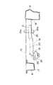
図3〜図5に示すように、フロアパネル15の下方において、車両1の前後方向にみて最後部に位置する第6クロスメンバ9と、この第6クロスメンバ9より1つ前側の第5クロスメンバ8との間には、スペアタイヤ14を支持するための支持ブラケット16が設けられている。この支持ブラケット16は、概ねその後端部18から左前方に向かって斜めに伸びるように配置されている。そして、詳しくは図示していないが、この支持ブラケット16の前端部17はボルト締結等により第5クロスメンバ8の下端面に固定され、他方後端部18は第6クロスメンバ9の前端面に固定されている。
Hereinafter, the storage structure of the
As shown in FIGS. 3 to 5, below the
そして、第5クロスメンバ8のやや後方において、支持ブラケット16にはスペアタイヤ取付部19が設けられ、このスペアタイヤ取付部19には、中空部を備えたパイプ状のケーブルガイド20が設けられている。このケーブルガイド20は、一方の端部が下方を向き、他方の端部がほぼ水平方向(支持ブラケット16の伸びる方向にみて後向き)を向き、両端部間でゆるやかに湾曲するエルボ状に形成されている。また、第6クロスメンバ9のやや前方において、支持ブラケット16には、ウインチ21(ケーブル巻き取り手段)が設けられている。このウインチ21は、ケーブル22(巻き上げケーブル)を巻き取り又は解き放つことができるようになっている(なお、ケーブル後端部はウインチ21から離脱することはない)。
Further, slightly behind the
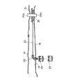
ここで、ケーブル22は、ウインチ21の外部では、概ね支持ブラケット16の伸びる方向にほぼ水平に伸び、ケーブルガイド20の中空部を通り抜けて支持ブラケット16の下方に突出している。そして、ケーブル22の先端部には、スペアタイヤ14と係合する係合部材23が取り付けられている。なお、係合部材23は、実質的に、上側支持板31と、下側支持板32と、両支持板31、32間に配置されたコイルスプリング33とで構成されている(図7参照)。ここで、上側支持板31の中心部には穴が形成され、ケーブル22はこの穴を通り抜けている。そして、ケーブル22の先端部は下側支持板32に固定されている。
Here, the
以下、ウインチ21の具体的な構造を説明する。
図6と図7とに示すように、ウインチ21には、ドライブシャフト25と、該ドライブシャフト25に同軸に取り付けられ外歯を備えたドライブギヤ26と、該ドライブギヤ26の外歯と噛み合う内歯を備えたドリブンギヤ27とが設けられている。そして、ドリブンギヤ27にはホイール29が同軸に取り付けられ、このホイール29にケーブル22が巻き取られるようになっている。なお、各ギヤ26、27とホイール29とは、ギヤケース28内に収容されている。また、ドリブンギヤ27は、ドライブギヤ26との噛み合いを確実化するために、一端がギヤケース28に取り付けられたばね30によって付勢されている。
Hereinafter, a specific structure of the
As shown in FIGS. 6 and 7, the
かくして、ドライブシャフト25が所定の巻き取り方向(例えば、上側からみて時計回り方向)に回転させられたときには、ドライブギヤ26がドライブシャフト25と一体回転する。これに伴って、ドライブギヤ26と噛み合っているドリブンギヤ27ひいてはホイール29が、ドライブシャフト25(ドライブギヤ26)の回転速度よりも遅い回転速度(例えば、1/10)で回転し、ケーブル22がホイール29に巻き取られる。なお、ドライブギヤ26とドリブンギヤ27の回転速度の比は、両ギヤ26、27の歯数によって決定される。このように、ドリブンギヤ27の回転速度がドライブギヤ26の回転速度よりも遅くなるので、ドライブシャフト25を回転させるのに要する力、すなわちケーブル22を巻き取るのに要する力の大きさは非常に小さくなる。つまり、非常に小さい力でウインチ21を巻き上げることができる。他方、ドライブシャフト25が逆方向に回転させられたときには、ホイール29が逆方向に回転し、ケーブル22は解き放たれる。
Thus, when the
このウインチ21は、ドライブシャフト25がほぼ上下方向に伸びるような位置関係でもって支持ブラケット16に固定されている。そして、図4に示されているように、ドライブシャフト25の上部はフロアパネル15に形成された穴部を通り抜けて車室内に突出する一方、下部は支持ブラケット16に形成された穴部を通り抜けて支持ブラケット16の下方に突出している。
The
そして、ドライブシャフト25の車室内に突出している部分には、該ドライブシャフトを回転させるための上側操作部25aが形成されている。他方、ドライブシャフト25の支持ブラケットの下方に突出している部分には、該ドライブシャフト25を回転させるための下側操作部25bが形成されている。つまり、ホイールナット用のレンチ等を用いてドライブシャフト25を回転させることができるようになっている。したがって、ウインチ21を操作するための格別の道具は必要とはされない。
An upper operation portion 25a for rotating the drive shaft is formed in a portion of the
かくして、係合部材23をスペアタイヤ14に係合させた状態で、ウインチ21によってケーブル22が巻き取られると、スペアタイヤ14がケーブル22によって持ち上げられてスペアタイヤ格納位置に格納される。また、ウインチ21によってケーブル22が解き放たれると、スペアタイヤ14がスペアタイヤ格納位置から下降させられて脱離させられる。
Thus, when the
以下、スペアタイヤ14を車両1のスペアタイヤ格納位置に格納し、又は該格納位置からスペアタイヤ14を脱離させるための具体的な手順を説明する。
スペアタイヤ14を車両1に格納する際には、まずケーブル22の先端部に取り付けられた係合部材23を、地面あるいは作業台等の上に置かれたスペアタイヤ14の中央開口部を上側から下向きに通り抜けさせ、係合部材23の上側支持板31をスペアタイヤ14の下面に係合させる。
Hereinafter, a specific procedure for storing the
When the
次に、ホイールナット用のレンチ等をウインチ21のドライブシャフト25の上側又は下側の操作部25a、25bにはめ込み、該レンチ等を所定の巻き取り方向(例えば、上側からみて時計回り方向)に回転させ、ケーブル22をホイール29に巻き取る。かくして、ケーブル22がホイール29に巻き取られてゆくのに伴って、スペアタイヤ14がケーブル22によって吊り上げられ、所定のスペアタイヤ格納位置まで持ち上げられる。なお、この場合、上側操作部25aを介してドライブシャフト25を回転させるときと、下側操作部25bを介してドライブシャフト25を回転させるときとでは、回転方向は逆方向となる。
Next, a wheel nut wrench or the like is fitted into the upper or
そして、スペアタイヤ14がスペアタイヤ格納位置まで持ち上げられた後、さらにケーブル22がホイール29に巻き取られると、上側支持板31及びスペアタイヤ14が停止した状態で、下側支持板32がコイルスプリング33の付勢力に抗してさらに上向きに引き上げられる。この後、下側支持板32は上側支持板31に当接して停止する(なお、これ以上はケーブル22を巻き取ることができない)。このとき、上側支持板31及びスペアタイヤ14は、コイルスプリング33の付勢力によって支持ブラケット16の下面に弾性的に押し付けられ、スペアタイヤ14が安定な状態で強固に保持(格納)される。
Then, after the
他方、スペアタイヤ14をスペアタイヤ格納位置から脱離させる際には、ホイールナット用のレンチ等をウインチ21のドライブシャフト25の上側又は下側の操作部25a、25bにはめ込み、該レンチ等を所定の解き放ち方向(例えば、上側からみて反時計回り方向)に回転させ、ケーブル22をホイール29から解き放つ。かくして、ケーブル22がホイール29から解き放たれてゆくのに伴って、まず下側支持板32のみが下降してコイルスプリング33の付勢力がリリースされ、この後係合部材23及びスペアタイヤ14が下降し、スペアタイヤ14が地面ないしは作業台の上に載せられる。この後、係合部材23をスペアタイヤ14の中央開口部から上方に抜き取り、スペアタイヤ14の脱離作業が完了する。
On the other hand, when the
このスペアタイヤ格納構造によれば、通常の運転時には、運転者は、車室側からウインチ21の上側操作部25aを操作することにより、スペアタイヤ14を容易に車両1に格納し、又は車両1から脱離させることができる。また、該車両1の生産時ないしは組み立て時には、作業者は、フロアパネル15の下側からウインチ21の下側操作部25bを操作することにより、格別の作業装置を用いることなく、床面(足場)に立った自然な姿勢でスペアタイヤ14を車両1に容易に格納することができる。
According to this spare tire storage structure, during normal driving, the driver can easily store the
図8に、車両1の生産時ないしは組み立て時における車両1と作業者42の位置関係の具体例を示す。図8に示すように、この具体例では、車両1は、適宜X方向に移動するハンガ40によって支持されている。そして、このハンガ40によって支持されている車両1にスペアタイヤ14を格納する際には、まずスペアタイヤ14が作業台41の上面に載せられる。次に、作業者42は、係合部材23を作業台41上のスペアタイヤ14に係合させた上で、ウインチ21の下側操作部25bをレンチ等で回転させてスペアタイヤ14を車両1に格納する。
FIG. 8 shows a specific example of the positional relationship between the vehicle 1 and the
その際、作業者42は、床面43に立った自然な状態で容易に下側操作部25bを操作することができる。これに対して、従来のスペアタイヤ格納構造のように、車室側のみからウインチ21を操作するようにした場合は、作業者42’は床面43に立った状態では、ウインチ21を操作することは極めて困難である。そこで、従来の生産ラインでは、格別の作業装置等を設けて、作業者42’を例えばLで示す位置まで持ち上げ、車室側からウインチ21を操作するようにしているが、かかる作業装置を設けると生産ラインを複雑化し、また作業装置への乗り降りがわずらわしいといった問題が生じるのは前記のとおりである。
At that time, the
以上、本発明にかかる車両のスペアタイヤ格納構造によれば、通常の運転時には運転者がスペアタイヤを容易に格納し又は脱離させることができるとともに、車両の生産時ないしは組み立て時には、作業者が格別の作業装置を用いることなくスペアタイヤを車両に容易に格納することができる。 As described above, according to the spare tire storage structure for a vehicle according to the present invention, the driver can easily store or remove the spare tire during normal operation, and the operator can operate the vehicle during production or assembly. The spare tire can be easily stored in the vehicle without using a special working device.
1…車両、2…左側サイドフレーム、3…右側サイドフレーム、4…第1クロスメンバ、5…第2クロスメンバ、6…第3クロスメンバ、7…第4クロスメンバ、8…第5クロスメンバ、9…第6クロスメンバ、10…左側前輪、11…右側前輪、12…左側後輪、13…右側後輪、14…スペアタイヤ、16…支持ブラケット、17…支持ブラケットの前端部、18…支持ブラケットの後端部、19…スペアタイヤ取付部、20…ケーブルガイド、21…ウインチ、22…ケーブル、23…係合部材、25…ドライブシャフト、25a…上側操作部、25b…下側操作部、26…ドライブギヤ、27…ドリブンギヤ、28…ギヤケース、29…ホイール、30…ばね、31…上側支持板、32…下側支持板、33…コイルスプリング、40…ハンガ、41…作業台、42…作業者、43…床面。 DESCRIPTION OF SYMBOLS 1 ... Vehicle, 2 ... Left side frame, 3 ... Right side frame, 4 ... 1st cross member, 5 ... 2nd cross member, 6 ... 3rd cross member, 7 ... 4th cross member, 8 ... 5th cross member , 9 ... Sixth cross member, 10 ... Left front wheel, 11 ... Right front wheel, 12 ... Left rear wheel, 13 ... Right rear wheel, 14 ... Spare tire, 16 ... Support bracket, 17 ... Front end of support bracket, 18 ... Rear end portion of support bracket, 19 ... spare tire mounting portion, 20 ... cable guide, 21 ... winch, 22 ... cable, 23 ... engagement member, 25 ... drive shaft, 25a ... upper operation portion, 25b ... lower operation portion , 26 ... drive gear, 27 ... driven gear, 28 ... gear case, 29 ... wheel, 30 ... spring, 31 ... upper support plate, 32 ... lower support plate, 33 ... coil spring, 40 Hanger, 41 ... work table, 42 ... workers, 43 ... floor.
Claims (7)
上記スペアタイヤと係合する係合部材を先端部に備え、上記フロアパネルより下側において水平方向に関して上記係合部材の近傍に設けられたスペアタイヤ取付部から垂下する巻き上げケーブルと、
上記車両側に取り付けられ、略水平状態に設置され上記巻き上げケーブルが巻かれる回転可能なホイールと、鉛直方向に伸び上記ホイールを回転駆動するドライブ軸とを備え、上記係合部材を上記スペアタイヤと係合させた状態で、上記巻き上げケーブルを巻き取り又は解き放つことにより上記スペアタイヤを格納し又は脱離させるケーブル巻き取り部とが設けられていて、
上記ケーブル巻き取り部が、上記フロアパネルより上側の車室側からと上記フロアパネルより下方の車外側とから巻き取り又は解き放ち操作が可能となるように、車両後部で上記フロアパネルの下方に配置され、
上記ドライブ軸は、上部が上記フロアパネルより上方に位置する上側操作部と、下方に形成された下側操作部とを備え、
上記スペアタイヤ取付部に、上記係合部材が上方位置にあるときに該係合部材の直ぐ上方に位置し上記巻き上げケーブルの伸びる方向を水平方向から下方に変えるケーブルガイドが設けられ、
上記ケーブル巻き取り部は、上記スペアタイヤ取付部より後方に位置する一方、上記スペアタイヤ取付部より後方に設けられ車幅方向に伸びる最後方メンバより前方に離間して上記ホイール部が上記ケーブルガイドと略同じ高さに位置するように配置され、
上記ケーブル巻き取り部の下側操作部は、上記最後方メンバの下面より上方に位置することを特徴とする車両のスペアタイヤ格納構造。 A spare tire storage structure for a vehicle configured to hold a spare tire in a substantially horizontal state on the lower surface side of the floor panel of the vehicle,
A winding cable that hangs from a spare tire mounting portion provided in the vicinity of the engagement member with respect to the horizontal direction below the floor panel;
A rotatable wheel attached to the vehicle side, installed in a substantially horizontal state and wound with the winding cable; and a drive shaft extending in a vertical direction to drive the wheel to rotate, and the engagement member is the spare tire In the engaged state, a cable take-up part for storing or removing the spare tire by winding or unwinding the winding cable is provided,
The cable winding portion is disposed below the floor panel at the rear of the vehicle so that the cable winding portion can be wound or unwound from the passenger compartment side above the floor panel and from the outside of the vehicle below the floor panel. And
The drive shaft includes an upper operation portion whose upper portion is located above the floor panel, and a lower operation portion formed below .
The spare tire mounting portion is provided with a cable guide that is located immediately above the engaging member when the engaging member is in the upper position and changes the extending direction of the hoisting cable from the horizontal direction to the lower side,
The cable winding portion is positioned rearward of the spare tire mounting portion, and is spaced forward from a rearmost member that is provided rearward of the spare tire mounting portion and extends in the vehicle width direction so that the wheel portion is connected to the cable guide. Are placed at the same height as
Lower operation section of the cable winding section, the spare tire storage structure for a vehicle, characterized in that located above the bottom surface of the rearmost member.
Priority Applications (1)
| Application Number | Priority Date | Filing Date | Title |
|---|---|---|---|
| JP2008110685A JP4636112B2 (en) | 2008-04-21 | 2008-04-21 | Spare tire storage structure for vehicle |
Applications Claiming Priority (1)
| Application Number | Priority Date | Filing Date | Title |
|---|---|---|---|
| JP2008110685A JP4636112B2 (en) | 2008-04-21 | 2008-04-21 | Spare tire storage structure for vehicle |
Related Parent Applications (1)
| Application Number | Title | Priority Date | Filing Date |
|---|---|---|---|
| JP23404998A Division JP4206523B2 (en) | 1998-08-20 | 1998-08-20 | Spare tire storage structure for vehicle |
Publications (2)
| Publication Number | Publication Date |
|---|---|
| JP2008179363A JP2008179363A (en) | 2008-08-07 |
| JP4636112B2 true JP4636112B2 (en) | 2011-02-23 |
Family
ID=39723581
Family Applications (1)
| Application Number | Title | Priority Date | Filing Date |
|---|---|---|---|
| JP2008110685A Expired - Fee Related JP4636112B2 (en) | 2008-04-21 | 2008-04-21 | Spare tire storage structure for vehicle |
Country Status (1)
| Country | Link |
|---|---|
| JP (1) | JP4636112B2 (en) |
Families Citing this family (1)
| Publication number | Priority date | Publication date | Assignee | Title |
|---|---|---|---|---|
| JP6256219B2 (en) * | 2014-06-17 | 2018-01-10 | トヨタ自動車株式会社 | Anti-theft structure for vehicle spare tires |
Family Cites Families (2)
| Publication number | Priority date | Publication date | Assignee | Title |
|---|---|---|---|---|
| JPS5868482U (en) * | 1981-10-31 | 1983-05-10 | 日野自動車株式会社 | Spare tires and carriers used in automobiles |
| US4600352A (en) * | 1984-07-18 | 1986-07-15 | Gulf & Western Manufacturing Company | Spare tire handling mechanism |
-
2008
- 2008-04-21 JP JP2008110685A patent/JP4636112B2/en not_active Expired - Fee Related
Also Published As
| Publication number | Publication date |
|---|---|
| JP2008179363A (en) | 2008-08-07 |
Similar Documents
| Publication | Publication Date | Title |
|---|---|---|
| JP4206523B2 (en) | Spare tire storage structure for vehicle | |
| JP3136222U (en) | Luggage unloading device | |
| CN111624002B (en) | A vehicle four-wheel alignment auxiliary device | |
| JP2019172043A (en) | Sunshade device and crane truck | |
| JP7028451B2 (en) | On-board cargo handling equipment | |
| JP2008179363A (en) | Spare tire storage structure for vehicle | |
| CN110723640B (en) | General hoisting tool for truck cab | |
| CN210617973U (en) | Sharing bicycle transportation trailer that two-layer was placed about | |
| JP2020150630A (en) | Electric work vehicle | |
| JPH11180352A (en) | Spare tire storage structure | |
| JP4899989B2 (en) | Spare tire transfer device | |
| JP6683595B2 (en) | Crawler work vehicle | |
| JP4743550B2 (en) | Spare tire storage structure | |
| JP4751197B2 (en) | Spare tire mounting device | |
| KR101670614B1 (en) | Detachable lifts for vehicles | |
| JP6088854B2 (en) | Wheel dolly | |
| CN218810120U (en) | Material storage and carrying tool car | |
| JPH09156543A (en) | Spare tire holding device for automobile | |
| KR100622102B1 (en) | Automatic choke detachment device for rolling roll and method thereof | |
| CN214734033U (en) | A kind of hoisting equipment for passenger car transmission | |
| CN211496753U (en) | Automobile machinery lifting device | |
| JP3189485U (en) | Carriage for motorcycles | |
| JP2011163101A (en) | Car stop block with lifting function | |
| JP4849440B2 (en) | Spare tire mounting device | |
| JP4141009B2 (en) | Tire storage rack |
Legal Events
| Date | Code | Title | Description |
|---|---|---|---|
| A977 | Report on retrieval |
Free format text: JAPANESE INTERMEDIATE CODE: A971007 Effective date: 20100611 |
|
| A131 | Notification of reasons for refusal |
Free format text: JAPANESE INTERMEDIATE CODE: A131 Effective date: 20100706 |
|
| A521 | Request for written amendment filed |
Free format text: JAPANESE INTERMEDIATE CODE: A523 Effective date: 20100906 |
|
| TRDD | Decision of grant or rejection written | ||
| A01 | Written decision to grant a patent or to grant a registration (utility model) |
Free format text: JAPANESE INTERMEDIATE CODE: A01 Effective date: 20101026 |
|
| A01 | Written decision to grant a patent or to grant a registration (utility model) |
Free format text: JAPANESE INTERMEDIATE CODE: A01 |
|
| A61 | First payment of annual fees (during grant procedure) |
Free format text: JAPANESE INTERMEDIATE CODE: A61 Effective date: 20101108 |
|
| FPAY | Renewal fee payment (event date is renewal date of database) |
Free format text: PAYMENT UNTIL: 20131203 Year of fee payment: 3 |
|
| R150 | Certificate of patent or registration of utility model |
Free format text: JAPANESE INTERMEDIATE CODE: R150 |
|
| LAPS | Cancellation because of no payment of annual fees |