JP4638112B2 - Method for producing gel cushion for reducing membrane effect - Google Patents
Method for producing gel cushion for reducing membrane effect Download PDFInfo
- Publication number
- JP4638112B2 JP4638112B2 JP2001572285A JP2001572285A JP4638112B2 JP 4638112 B2 JP4638112 B2 JP 4638112B2 JP 2001572285 A JP2001572285 A JP 2001572285A JP 2001572285 A JP2001572285 A JP 2001572285A JP 4638112 B2 JP4638112 B2 JP 4638112B2
- Authority
- JP
- Japan
- Prior art keywords
- cushion
- film
- membrane
- gel
- mold
- Prior art date
- Legal status (The legal status is an assumption and is not a legal conclusion. Google has not performed a legal analysis and makes no representation as to the accuracy of the status listed.)
- Expired - Fee Related
Links
Images




Classifications
-
- B—PERFORMING OPERATIONS; TRANSPORTING
- B29—WORKING OF PLASTICS; WORKING OF SUBSTANCES IN A PLASTIC STATE IN GENERAL
- B29C—SHAPING OR JOINING OF PLASTICS; SHAPING OF MATERIAL IN A PLASTIC STATE, NOT OTHERWISE PROVIDED FOR; AFTER-TREATMENT OF THE SHAPED PRODUCTS, e.g. REPAIRING
- B29C65/00—Joining or sealing of preformed parts, e.g. welding of plastics materials; Apparatus therefor
- B29C65/02—Joining or sealing of preformed parts, e.g. welding of plastics materials; Apparatus therefor by heating, with or without pressure
- B29C65/18—Joining or sealing of preformed parts, e.g. welding of plastics materials; Apparatus therefor by heating, with or without pressure using heated tools
-
- B—PERFORMING OPERATIONS; TRANSPORTING
- B29—WORKING OF PLASTICS; WORKING OF SUBSTANCES IN A PLASTIC STATE IN GENERAL
- B29C—SHAPING OR JOINING OF PLASTICS; SHAPING OF MATERIAL IN A PLASTIC STATE, NOT OTHERWISE PROVIDED FOR; AFTER-TREATMENT OF THE SHAPED PRODUCTS, e.g. REPAIRING
- B29C66/00—General aspects of processes or apparatus for joining preformed parts
- B29C66/01—General aspects dealing with the joint area or with the area to be joined
- B29C66/05—Particular design of joint configurations
- B29C66/10—Particular design of joint configurations particular design of the joint cross-sections
- B29C66/11—Joint cross-sections comprising a single joint-segment, i.e. one of the parts to be joined comprising a single joint-segment in the joint cross-section
- B29C66/112—Single lapped joints
-
- B—PERFORMING OPERATIONS; TRANSPORTING
- B29—WORKING OF PLASTICS; WORKING OF SUBSTANCES IN A PLASTIC STATE IN GENERAL
- B29C—SHAPING OR JOINING OF PLASTICS; SHAPING OF MATERIAL IN A PLASTIC STATE, NOT OTHERWISE PROVIDED FOR; AFTER-TREATMENT OF THE SHAPED PRODUCTS, e.g. REPAIRING
- B29C66/00—General aspects of processes or apparatus for joining preformed parts
- B29C66/01—General aspects dealing with the joint area or with the area to be joined
- B29C66/05—Particular design of joint configurations
- B29C66/10—Particular design of joint configurations particular design of the joint cross-sections
- B29C66/11—Joint cross-sections comprising a single joint-segment, i.e. one of the parts to be joined comprising a single joint-segment in the joint cross-section
- B29C66/112—Single lapped joints
- B29C66/1122—Single lap to lap joints, i.e. overlap joints
-
- B—PERFORMING OPERATIONS; TRANSPORTING
- B29—WORKING OF PLASTICS; WORKING OF SUBSTANCES IN A PLASTIC STATE IN GENERAL
- B29C—SHAPING OR JOINING OF PLASTICS; SHAPING OF MATERIAL IN A PLASTIC STATE, NOT OTHERWISE PROVIDED FOR; AFTER-TREATMENT OF THE SHAPED PRODUCTS, e.g. REPAIRING
- B29C66/00—General aspects of processes or apparatus for joining preformed parts
- B29C66/01—General aspects dealing with the joint area or with the area to be joined
- B29C66/05—Particular design of joint configurations
- B29C66/10—Particular design of joint configurations particular design of the joint cross-sections
- B29C66/11—Joint cross-sections comprising a single joint-segment, i.e. one of the parts to be joined comprising a single joint-segment in the joint cross-section
- B29C66/116—Single bevelled joints, i.e. one of the parts to be joined being bevelled in the joint area
-
- B—PERFORMING OPERATIONS; TRANSPORTING
- B29—WORKING OF PLASTICS; WORKING OF SUBSTANCES IN A PLASTIC STATE IN GENERAL
- B29C—SHAPING OR JOINING OF PLASTICS; SHAPING OF MATERIAL IN A PLASTIC STATE, NOT OTHERWISE PROVIDED FOR; AFTER-TREATMENT OF THE SHAPED PRODUCTS, e.g. REPAIRING
- B29C66/00—General aspects of processes or apparatus for joining preformed parts
- B29C66/50—General aspects of joining tubular articles; General aspects of joining long products, i.e. bars or profiled elements; General aspects of joining single elements to tubular articles, hollow articles or bars; General aspects of joining several hollow-preforms to form hollow or tubular articles
- B29C66/51—Joining tubular articles, profiled elements or bars; Joining single elements to tubular articles, hollow articles or bars; Joining several hollow-preforms to form hollow or tubular articles
- B29C66/53—Joining single elements to tubular articles, hollow articles or bars
- B29C66/534—Joining single elements to open ends of tubular or hollow articles or to the ends of bars
-
- B—PERFORMING OPERATIONS; TRANSPORTING
- B29—WORKING OF PLASTICS; WORKING OF SUBSTANCES IN A PLASTIC STATE IN GENERAL
- B29C—SHAPING OR JOINING OF PLASTICS; SHAPING OF MATERIAL IN A PLASTIC STATE, NOT OTHERWISE PROVIDED FOR; AFTER-TREATMENT OF THE SHAPED PRODUCTS, e.g. REPAIRING
- B29C66/00—General aspects of processes or apparatus for joining preformed parts
- B29C66/80—General aspects of machine operations or constructions and parts thereof
- B29C66/81—General aspects of the pressing elements, i.e. the elements applying pressure on the parts to be joined in the area to be joined, e.g. the welding jaws or clamps
- B29C66/812—General aspects of the pressing elements, i.e. the elements applying pressure on the parts to be joined in the area to be joined, e.g. the welding jaws or clamps characterised by the composition, by the structure, by the intensive physical properties or by the optical properties of the material constituting the pressing elements, e.g. constituting the welding jaws or clamps
- B29C66/8124—General aspects of the pressing elements, i.e. the elements applying pressure on the parts to be joined in the area to be joined, e.g. the welding jaws or clamps characterised by the composition, by the structure, by the intensive physical properties or by the optical properties of the material constituting the pressing elements, e.g. constituting the welding jaws or clamps characterised by the structure of the material constituting the pressing elements, e.g. constituting the welding jaws or clamps
- B29C66/81241—General aspects of the pressing elements, i.e. the elements applying pressure on the parts to be joined in the area to be joined, e.g. the welding jaws or clamps characterised by the composition, by the structure, by the intensive physical properties or by the optical properties of the material constituting the pressing elements, e.g. constituting the welding jaws or clamps characterised by the structure of the material constituting the pressing elements, e.g. constituting the welding jaws or clamps being porous or sintered
-
- B—PERFORMING OPERATIONS; TRANSPORTING
- B29—WORKING OF PLASTICS; WORKING OF SUBSTANCES IN A PLASTIC STATE IN GENERAL
- B29C—SHAPING OR JOINING OF PLASTICS; SHAPING OF MATERIAL IN A PLASTIC STATE, NOT OTHERWISE PROVIDED FOR; AFTER-TREATMENT OF THE SHAPED PRODUCTS, e.g. REPAIRING
- B29C66/00—General aspects of processes or apparatus for joining preformed parts
- B29C66/80—General aspects of machine operations or constructions and parts thereof
- B29C66/83—General aspects of machine operations or constructions and parts thereof characterised by the movement of the joining or pressing tools
- B29C66/832—Reciprocating joining or pressing tools
- B29C66/8322—Joining or pressing tools reciprocating along one axis
-
- B—PERFORMING OPERATIONS; TRANSPORTING
- B29—WORKING OF PLASTICS; WORKING OF SUBSTANCES IN A PLASTIC STATE IN GENERAL
- B29D—PRODUCING PARTICULAR ARTICLES FROM PLASTICS OR FROM SUBSTANCES IN A PLASTIC STATE
- B29D12/00—Producing frames
- B29D12/02—Spectacle frames
-
- G—PHYSICS
- G02—OPTICS
- G02C—SPECTACLES; SUNGLASSES OR GOGGLES INSOFAR AS THEY HAVE THE SAME FEATURES AS SPECTACLES; CONTACT LENSES
- G02C5/00—Constructions of non-optical parts
-
- G—PHYSICS
- G02—OPTICS
- G02C—SPECTACLES; SUNGLASSES OR GOGGLES INSOFAR AS THEY HAVE THE SAME FEATURES AS SPECTACLES; CONTACT LENSES
- G02C5/00—Constructions of non-optical parts
- G02C5/12—Nose pads; Nose-engaging surfaces of bridges or rims
- G02C5/126—Nose pads; Nose-engaging surfaces of bridges or rims exchangeable or otherwise fitted to the shape of the nose
-
- B—PERFORMING OPERATIONS; TRANSPORTING
- B29—WORKING OF PLASTICS; WORKING OF SUBSTANCES IN A PLASTIC STATE IN GENERAL
- B29C—SHAPING OR JOINING OF PLASTICS; SHAPING OF MATERIAL IN A PLASTIC STATE, NOT OTHERWISE PROVIDED FOR; AFTER-TREATMENT OF THE SHAPED PRODUCTS, e.g. REPAIRING
- B29C2791/00—Shaping characteristics in general
- B29C2791/004—Shaping under special conditions
- B29C2791/006—Using vacuum
-
- B—PERFORMING OPERATIONS; TRANSPORTING
- B29—WORKING OF PLASTICS; WORKING OF SUBSTANCES IN A PLASTIC STATE IN GENERAL
- B29C—SHAPING OR JOINING OF PLASTICS; SHAPING OF MATERIAL IN A PLASTIC STATE, NOT OTHERWISE PROVIDED FOR; AFTER-TREATMENT OF THE SHAPED PRODUCTS, e.g. REPAIRING
- B29C51/00—Shaping by thermoforming, i.e. shaping sheets or sheet like preforms after heating, e.g. shaping sheets in matched moulds or by deep-drawing; Apparatus therefor
- B29C51/10—Forming by pressure difference, e.g. vacuum
-
- B—PERFORMING OPERATIONS; TRANSPORTING
- B29—WORKING OF PLASTICS; WORKING OF SUBSTANCES IN A PLASTIC STATE IN GENERAL
- B29C—SHAPING OR JOINING OF PLASTICS; SHAPING OF MATERIAL IN A PLASTIC STATE, NOT OTHERWISE PROVIDED FOR; AFTER-TREATMENT OF THE SHAPED PRODUCTS, e.g. REPAIRING
- B29C51/00—Shaping by thermoforming, i.e. shaping sheets or sheet like preforms after heating, e.g. shaping sheets in matched moulds or by deep-drawing; Apparatus therefor
- B29C51/26—Component parts, details or accessories; Auxiliary operations
- B29C51/30—Moulds
- B29C51/34—Moulds for undercut articles
- B29C51/343—Moulds for undercut articles having recessed undersurfaces
-
- B—PERFORMING OPERATIONS; TRANSPORTING
- B29—WORKING OF PLASTICS; WORKING OF SUBSTANCES IN A PLASTIC STATE IN GENERAL
- B29C—SHAPING OR JOINING OF PLASTICS; SHAPING OF MATERIAL IN A PLASTIC STATE, NOT OTHERWISE PROVIDED FOR; AFTER-TREATMENT OF THE SHAPED PRODUCTS, e.g. REPAIRING
- B29C66/00—General aspects of processes or apparatus for joining preformed parts
- B29C66/50—General aspects of joining tubular articles; General aspects of joining long products, i.e. bars or profiled elements; General aspects of joining single elements to tubular articles, hollow articles or bars; General aspects of joining several hollow-preforms to form hollow or tubular articles
- B29C66/51—Joining tubular articles, profiled elements or bars; Joining single elements to tubular articles, hollow articles or bars; Joining several hollow-preforms to form hollow or tubular articles
- B29C66/53—Joining single elements to tubular articles, hollow articles or bars
- B29C66/534—Joining single elements to open ends of tubular or hollow articles or to the ends of bars
- B29C66/5346—Joining single elements to open ends of tubular or hollow articles or to the ends of bars said single elements being substantially flat
- B29C66/53461—Joining single elements to open ends of tubular or hollow articles or to the ends of bars said single elements being substantially flat joining substantially flat covers and/or substantially flat bottoms to open ends of container bodies
-
- B—PERFORMING OPERATIONS; TRANSPORTING
- B29—WORKING OF PLASTICS; WORKING OF SUBSTANCES IN A PLASTIC STATE IN GENERAL
- B29C—SHAPING OR JOINING OF PLASTICS; SHAPING OF MATERIAL IN A PLASTIC STATE, NOT OTHERWISE PROVIDED FOR; AFTER-TREATMENT OF THE SHAPED PRODUCTS, e.g. REPAIRING
- B29C66/00—General aspects of processes or apparatus for joining preformed parts
- B29C66/70—General aspects of processes or apparatus for joining preformed parts characterised by the composition, physical properties or the structure of the material of the parts to be joined; Joining with non-plastics material
- B29C66/71—General aspects of processes or apparatus for joining preformed parts characterised by the composition, physical properties or the structure of the material of the parts to be joined; Joining with non-plastics material characterised by the composition of the plastics material of the parts to be joined
-
- B—PERFORMING OPERATIONS; TRANSPORTING
- B29—WORKING OF PLASTICS; WORKING OF SUBSTANCES IN A PLASTIC STATE IN GENERAL
- B29C—SHAPING OR JOINING OF PLASTICS; SHAPING OF MATERIAL IN A PLASTIC STATE, NOT OTHERWISE PROVIDED FOR; AFTER-TREATMENT OF THE SHAPED PRODUCTS, e.g. REPAIRING
- B29C66/00—General aspects of processes or apparatus for joining preformed parts
- B29C66/80—General aspects of machine operations or constructions and parts thereof
- B29C66/81—General aspects of the pressing elements, i.e. the elements applying pressure on the parts to be joined in the area to be joined, e.g. the welding jaws or clamps
- B29C66/812—General aspects of the pressing elements, i.e. the elements applying pressure on the parts to be joined in the area to be joined, e.g. the welding jaws or clamps characterised by the composition, by the structure, by the intensive physical properties or by the optical properties of the material constituting the pressing elements, e.g. constituting the welding jaws or clamps
- B29C66/8122—General aspects of the pressing elements, i.e. the elements applying pressure on the parts to be joined in the area to be joined, e.g. the welding jaws or clamps characterised by the composition, by the structure, by the intensive physical properties or by the optical properties of the material constituting the pressing elements, e.g. constituting the welding jaws or clamps characterised by the composition of the material constituting the pressing elements, e.g. constituting the welding jaws or clamps
-
- B—PERFORMING OPERATIONS; TRANSPORTING
- B29—WORKING OF PLASTICS; WORKING OF SUBSTANCES IN A PLASTIC STATE IN GENERAL
- B29L—INDEXING SCHEME ASSOCIATED WITH SUBCLASS B29C, RELATING TO PARTICULAR ARTICLES
- B29L2012/00—Frames
- B29L2012/005—Spectacle frames
-
- B—PERFORMING OPERATIONS; TRANSPORTING
- B29—WORKING OF PLASTICS; WORKING OF SUBSTANCES IN A PLASTIC STATE IN GENERAL
- B29L—INDEXING SCHEME ASSOCIATED WITH SUBCLASS B29C, RELATING TO PARTICULAR ARTICLES
- B29L2022/00—Hollow articles
- B29L2022/02—Inflatable articles
-
- B—PERFORMING OPERATIONS; TRANSPORTING
- B29—WORKING OF PLASTICS; WORKING OF SUBSTANCES IN A PLASTIC STATE IN GENERAL
- B29L—INDEXING SCHEME ASSOCIATED WITH SUBCLASS B29C, RELATING TO PARTICULAR ARTICLES
- B29L2031/00—Other particular articles
- B29L2031/751—Mattresses, cushions
Landscapes
- Engineering & Computer Science (AREA)
- Mechanical Engineering (AREA)
- Physics & Mathematics (AREA)
- Health & Medical Sciences (AREA)
- General Physics & Mathematics (AREA)
- Ophthalmology & Optometry (AREA)
- Optics & Photonics (AREA)
- Casting Or Compression Moulding Of Plastics Or The Like (AREA)
- Moulds For Moulding Plastics Or The Like (AREA)
- Blow-Moulding Or Thermoforming Of Plastics Or The Like (AREA)
- Eyeglasses (AREA)
Description
【0001】
【発明の属する技術分野】
本発明は、欧州特許出願第EP96400277号に記述されたタイプの膜効果を低減させるゲル状クッションの製造方法に関する。
【0002】
【従来の技術】
従来の技術として、図1A、1Bおよび1Cには、欧州特許出願第EP96400277号において説明され、そこに開示された発明によって解決された技術的課題が示されている。図1Aには、眼鏡フレームに用いられる鼻当ての形状をした従来構造のゲル状クッション1が示されている。クッション1は、熱成形された薄い弾性膜2と、膜2の縁部が封止または接着された支持パッド3とを備えている。膜2は、支持パッド3の前面とともに、一般にシリコンゲルからなるゲル状物質4が封入された密閉ポケットを形成している。
【0003】
クッション1が押しつぶされたとき、特に、クッション1が鼻に対して押しつけられたときには、ゲル状物質4がクッション1に加わる圧力および衝撃を吸収することにより優れた快適性を提供するようになっている。しかしながら、クッション1が押しつぶされたときの反応をより注意深く考察した場合には、図1Bに示すように、クッション1に加わる圧力の増加に伴って、ゲル状物質4が圧縮されて膜2が伸張することにより、膜2の伸張効果が優勢になってゲル状物質4のゲル効果が失われることがわかる。このような伸張効果は、欧州特許出願第EP96400277号において“膜効果”として言及されている。したがって、クッション1が鼻に対して押しつけられたときには、図1Cに示すように、クッション1が眼鏡フレームの自重によって押しつぶされ、膜効果がゲル効果よりも支配的になっている。このような結果は、明らかに快適性を損なわせるものである。
【0004】
図2Aは、欧州特許出願第EP96400277号に記述されたタイプの膜効果を低減させるゲル状クッションの一例としてのクッション5の断面図である。クッション5は、上述したような不都合が生じないものである。クッション5は、上述したクッションのように、ゲル状物質7を密閉する柔軟性膜6と、膜6の縁部が封止された支持パッド8とを備えている。膜6は、少なくとも1つの折り目、ここでは、クッション5の内側に向かう2つの折り目9、9’を有している。折り目9、9’は、クッション5の表面にスリットを形成している。ゲル状物質7は、折り目9、9’の正確な形状を保持するようになっている。クッション5が押しつぶされたときには、図2Bに示すように、圧縮されたゲル状物質7によって膜6が押圧され、膜6の折り目9、9’が開くようになっている。このように、膜6が押圧されたときに膜6の折り目9、9’が開くことによって膜6の表面が広がるので、膜6が伸張した状態に達する瞬間を先に延ばすことが可能となる。したがって、クッション5が押しつぶされたときの反応は、矢印で示すように、主にゲル状物質7が作用するようになっている。このとき、膜効果によって膜6が伸張する感覚は、取り除かれているか、または、少なくともその発生が先に延ばされている。このような結果は、クッション5によって提供される快適性を著しく向上させるものである。
【0005】
図3には、上述した欧州特許出願に記述されたクッションの製造工程が示されている。この製造工程では、まず、少なくとも1つの折り目、例えば、図2Aに示したクッション5の折り目9、9’に対応する2つの折り目11、11’が底部に設けられた熱成形金型10を準備する。次に、膜6が熱源によって柔らかくされ、吸引装置12によって金型10の底部に押しつけられる。このようにして形成されたクッションキャビティには、重合されてゲル状に固化するようになされた液体配合物7が充填される。次に、液体配合物7が完全に重合される前に、上述した支持パッド8が配置され、膜6の縁部が支持パッド8に封止されることにより、クッション5が密封される。そして、クッション5が密封された後に、液体配合物7が完全に重合されて、クッション5の製造工程を終了する。
【0006】
【発明が解決しようとする課題】
本発明の目的は、膜効果を低減させるクッションの製造方法として、上述したクッションに代わるものを構成することができる製造方法を提供することである。
【0007】
実際には、上述した従来の製造方法は、それ自体において少しも不都合を生じさせるものではなく、例えば、利用可能な製造設備、作業員の専門知識、製造に要する費用などに応じて最適な方法を選択するために、異なる方法によって同様の製品を生産する産業分野において、常に有用であり十分な満足を提供するものである。
【0008】
本発明の他の目的は、これまでに実施された膜効果を低減させるクッションの変形態様を提供することである。
【0009】
【課題を解決するための手段】
この目的は、膜によって少なくとも一部が密閉されたゲル状物質を備えた眼鏡フレームの鼻当て用のゲル状クッションの製造方法であって、前記膜を金型の中で熱成形する熱成形工程と、熱成形後の前記膜で囲まれた内部に重合後にゲル状に固化するように調合された液体配合物を充填する充填工程と、熱成形後の前記膜の縁部にクッション支持部材を封止または接着することにより前記液体配合物を前記膜で囲まれた内部に密封する密封工程と、前記液体配合物がゲル状物質に固化されるように前記液体配合物を重合する重合工程と、を有するゲル状クッションの製造方法において、前記熱成形工程の後において、熱成形後の前記膜の少なくとも一箇所に変形力を加えて前記膜を変形させる変形工程をさらに有し、前記変形工程の前記変形力を、前記密封工程の後であって、かつ前記液体配合物が完全に固化する前に解除し、前記膜の表面に少なくとも1つの凹部または起伏部を永続的に保持させる製造方法を提供することにより達成される。
【0010】
一実施形態によれば、前記変形工程は、前記充填工程の前において、熱成形後の前記膜が前記金型の中に位置している間に、前記膜の一部が前記金型から完全に引き離され、前記膜の他部が吸引によって保持されるように前記膜の少なくとも一箇所に変形力を加えることによって行う。
【0011】
一実施形態によれば、前記変形工程は、前記膜に前記変形力を加えるように前記金型の内側に向かって移動する少なくとも1つの可動部を備えた金型手段によって行われる。
【0012】
一実施形態によれば、前記金型は、柔軟性および弾性を有する部材によって形成され、前記金型が変形することにより前記膜が変形するように設けられたものであり、前記変形工程は、前記充填工程の前において、熱成形後の前記膜が前記金型の中に位置している間に、前記金型を完全に変形させるように、前記金型の少なくとも一箇所に変形力を加えることによって行う。
【0013】
一実施形態によれば、前記膜の前記変形工程は、前記密封工程の後であって、かつ前記液体配合物が重合される間において、前記膜の少なくとも一箇所に変形力を加えることによって行い、前記液体配合物が重合した後に、前記ゲル状物質の形状保持効果によって前記膜の形状が最終的に形成される。
【0014】
一実施形態によれば、前記変形力は、前記重合工程が終了したときに前記膜の表面に押跡を残すように設けられた少なくとも1つの凸部を表面に有する部材を熱成形後の前記膜の表面に押しつけることによって得られる。
【0015】
一実施形態によれば、前記クッション支持部材の厚さは、前記膜の厚さよりも大きくなるように設けられ、前記膜の縁部は、前記クッション支持部材の前記ゲル状物質側の一面に対して1°から90°までの間の角度をなすように、前記クッション支持部材に封止された。
【0016】
本発明は、また、上述した製造方法によって製造されたゲル状クッションに関する。
【0017】
一実施形態によれば、前記膜は、押跡によって形成された所定の形状を有する。
【0018】
一実施形態によれば、前記膜の縁部は、前記クッション支持部材の前記ゲル状物質側の一面に対して1°から90°までの間の角度をなすように、前記クッション支持部材の端部に封止された。
【0019】
一実施形態によれば、前記膜は、ポリウレタンフィルムからなる。
【0020】
一実施形態によれば、前記膜は、併置された2枚の柔軟性フィルムを備えた。
【0021】
一実施形態によれば、前記ゲル状物質は、シリコンゲルからなる。
【0022】
一実施形態によれば、前記クッション支持部材の前記ゲル状物質側の一面に、前記膜と前記クッション支持部材との間に封入された前記ゲル状物質の拡大効果によって拡大されるマークを備えた。
【0023】
本発明のこれらおよび他の目的、特徴および効果は、本発明に係る製造方法およびその製造方法によって製造された膜効果を低減させるクッションの2つの実施形態に関する以下の記述において、以下の図面に関係して、より詳細に説明される。
【0024】
【発明の実施の形態】
図4Aから4Dには、本発明に係る膜効果を低減させるゲル状クッションの製造方法の主要工程が示されている。
【0025】
第1の製造工程において、柔軟性膜20は、折り目のない、なだらかに湾曲した形状を有する従来形状の多孔性金型30の中で熱成形される。膜30は、例えば、厚さが10分の数マイクロメータであるポリウレタンフィルムからなるものである。一変形態様として、膜30は、重ね合わされた2枚の薄いポリウレタンフィルム(図示されていない)によって構成されている。金型30は、吸引チャンバ32を備えたフレーム31と一体に設けられている。吸引チャンバ32は、ポンプ装置33に連結されている。熱成型は、赤外線IRなどの熱源の存在下で行われる。ポンプ装置33が作動することにより、膜20が吸引されて金型30の底部に押しつけられ、金型の形状に一致するクッションキャビティ40が形成される。
【0026】
そして、本発明によれば、膜20は、クッションキャビティ40の体積を減少させるように、表面の少なくとも1箇所において変形される。このために、金型30は、少なくとも1つの変形可能な領域を備えている。この変形可能な領域は、図4Bに示すように、フレーム31の中に摺動可能に設けられた可動部34によって構成されている。可動部34の上端は、金型30の内側に露出している。
【0027】
したがって、図4Bに示した工程においては、吸引が維持されるとともに、可動部34が金型の中心に向かって押し込まれる。可動部34の上端は、膜20を押圧することによって膜20の一部を金型30から引き離す凸部を構成している。膜の他部は、吸引によって金型30に押しつけられたままである。2つまたは3つの成分を有する重合可能な液体配合物21をクッションキャビティ40に充填するときには、膜20に加えられた変形力が維持されている。液体配合物21は、好ましくは、シリコンをベースにした配合物からなるものである。
【0028】
図4Cに示した工程において、プラスチックからなるパッド22によってクッションキャビティ40が密封されるときには、膜20に加えられた変形力がそのまま維持されている。パッド22は、これから先において、クッション40の支持パッドを構成するようになっている。パッド22は、膜20の縁部に接触するように、熱成形キャビティの角部に押しつけられている。膜20の縁部は、平らな環状の抵抗35を用いた従来の方法によってパッド22に封止される。抵抗35は、熱成形キャビティの角部に位置するように、金型30に埋め込まれている。抵抗35は、電流Iを供給する電源36に連結され、非常に短い時間のうちに温度が200°まで達するようになっている。この封止工程においては、膜20とパッド22との間に位置する液体配合物21を押し出すように、かなり大きな押圧力が支持パッド22に加えられている。
【0029】
本発明によれば、可動部34によって膜20に加えられた変形力は、クッション40が密封された後であって、液体配合物21が完全に重合される前に解除される。圧力から解放された後に現れるクッション40の形状は、限定されるものではなく単なる参考として、図4Dに例示されている。この形状は、膜20に作用する熱成形により付与された初期形状に復帰しようとする表面張力とクッション40内の内圧とのバランスの結果であるので、ランダムな形状となり、明確に記述することができない。実際、液体配合物21が広がることもなく、空気が密閉されているクッション40の中に入ることもない。そして、このような、少なくとも1つの凹部または起伏部を有するクッション40の形状は、常温でまたは加熱器の中において液体配合物21を重合する(架橋する)ことにより、最終形状に固定される。
【0030】
このような、少なくとも1つの凹部または起伏部を有するクッション40の形状は、欧州特許出願第EP96400277号に記述されたスリットを形成する少なくとも1つの折り目を有するクッションの形状と同様の機能を果たすようになっている。実際に、クッションが押しつぶされたときには、膜20の表面が広がるので、それだけ膜効果の発生を先に延ばすことが可能となる。
【0031】
上述した製造方法において他の変形態様および実施形態が可能であることは、当業者によって理解できることである。特に、金型30は、凸部を構成する複数の可動部として、例えば、熱成形キャビティの角部近傍に配置された2つの可動部を備えてもよい。他の変形態様によれば、金型30は、柔軟性のある弾性材料によって形成されてもよい。この場合には、変形力が金型の底部に直接加えられることによって金型が変形し、同時に膜が変形する。また、変形力が解除されることによって金型が初期形状に戻る。さらには、金型に形成された少なくとも1つの孔を介して膜に圧縮空気を吹き付ける手段、または、変形可能な金型に圧縮空気を吹き付ける手段によって変形力を加えるように構成してもよい。
【0032】
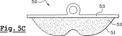
図5Aから5Cには、本発明の第2実施形態に係る製造方法が示されている。ここで、従来の方法によって製造されたクッション50は、熱成形された膜51と、まだ重合されていない液体配合物52と、支持パッド53とを備えている。クッション50の表面は、図5Aに示すように、液体配合物52が完全に重合される前に、クッション50が構造部材55に向かって相対的に移動することにより、構造部材55に押しつけられる。構造部材55は、略平らな面と、凸部56を構成する少なくとも1つの部分とを備えている。
【0033】
凸部56を構成する部分は、図5Bに示すように、クッションの膜51を変形させる。液体配合物52が重合されるときには、構造部材55がクッション50を押圧している。重合が終了したときには、膜51が、図5Cに示すように、凸部56を構成する部分の押跡によって形成された少なくとも1つの凹部または起伏部を有している。この形状は、ゲル状物質52の形状保持効果によって最終形状になる。また、長時間にわたって押しつぶされた後であっても、常にこの形状に戻るようになっている。この形状は、上述したクッションのように、押しつぶされたときに膜51が広がるので、膜効果を低減させることが可能となる。
【0034】
本発明の第1実施形態に係る製造方法とは違って、ここでは、クッション50が密封された後に変形力を加えているため、一定の体積のままで膜が変形されるようになっている。液体配合物52を圧縮することができないため、クッションの体積を減少させることができない。したがって、上述した2つの製造工程は、膜が熱成形された後であって、液体配合物が完全に重合される前に、クッションの膜を弾性的に変形させる工程を備えているという類似した特徴を有している。また、第1の場合においては、液体配合物が充填される前に変形が行われ、第2の場合においては、液体配合物が充填された後であって、クッションが密封された後に変形が行われるという差異を有している。
【0035】
本発明の第2実施形態に係る製造方法においては、さらに、他の変形態様が可能である。例えば、上述した金型30の可動部34からなる手段によって、クッションの変形が行われるように構成してもよい。この場合には、支持パッドからなる手段によってクッションが密封された後に、可動部34が膜を押圧するようになるが、変形させる工程は、図4Cに示した工程によって行われる。この場合には、金型の中で重合が行われる。さらに、図5Aおよび5Bに示した構造部材55は、寸法が小さいまたは大きい複数の凸部を備えてもよく、例えば、鋸歯状に設けられた複数の凸部を備えてもよい。また、図6に示すように、重合されていない液体配合物62を備えたクッション60の膜61の変形が、網目状の部材65からなる手段によって行われるように構成してもよい。重合が終了したときには、網目状の部材65がクッション60に押跡を残している。そして、クッション60は、複数の起伏部を含んだ形状を有している。
【0036】
概して、上述した製造工程が、複数のクッションをまとめて製造するもの、特に、複数の熱成形キャビティを備えた金型設備に有用であることは、理解できることである。この場合には、複数の支持パッドに分割される大きな1つの支持パッドからなる手段を用いることにより、複数のクッションを連結して製造することが可能となる。大きな1つの支持パッドは、例えば、打ち抜き加工によって、複数の支持パッドに分割される。
【0037】
図7には、本発明の一実施形態に係るクッション70が示されている。クッション70は、膜72の縁部を封止する構成が上述したクッションと異なっている。膜72の縁部は、支持パッド71のゲル状物質側の一面に対して0°と異なる角度“A”をなすように、支持パッド71に封止されている。このように構成するため、膜72は、角度“A”をなすように斜めに設けられた支持パッド71の周部に封止されている。実際には、角度“A”は、1°から90°までの間の角度にすることができる(まっすぐな側面に封止するように)。角度“A”が0°である場合は、上述したクッションのように、一平面に封止された場合に対応している。
【0038】
さらに、出願人によって考えられた他の改良態様は、ゲル状クッションのマークに関するものである。このマークの目的は、通し番号、商標、装飾的な頭文字または他の単語、クッションに表示する必要があるロゴまたはデザインなどを形成することにある。このマークは、インクジェット印刷方法などの非破壊的な方法からなる手段によって、クッションの膜に形成されてもよい。しかしながら、この方法では、仕上げが精密になり、実施が高価になってしまう。
【0039】
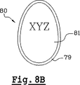
本発明に係る改良態様は、図8Aに示すように、膜が支持パッドに封止される前に、クッションの支持パッド79の内側にマーク、例えば、文字“xyz”を形成することである。ほとんどの場合、特に、鼻当ての場合には、支持パッド79は、膜よりも厚くて強いので、レーザ加工のような研削加工を用いることができる。クッション80が完成したときには、図8Bに示すように、支持パッド79と膜との間に封入された透光性のゲル状物質81の拡大効果によって、マークが拡大される。当初のマーク(xyz)は、図8Bに示すように、(XYZ)に拡大されて現れる。
【図面の簡単な説明】
図1A、1B、1Cは、従来の衝撃吸収クッションを示している。
図2Aおよび2Bは、従来の膜効果を低減させるクッションの断面図である。
図3は、従来の膜効果を低減させるクッションの製造工程を示している。
図4Aから4Dは、本発明の第1実施形態に係る膜効果を低減させるクッションの製造工程を示している。
図5Aから5Cは、本発明の第2実施形態に係る膜効果を低減させるクッションの製造工程を示している。
図6は、本発明の第2実施形態に係る製造工程の変形態様を示している。
図7は、本発明の一実施形態に係るゲル状クッションを示している。
図8Aおよび8Bは、本発明に係るクッションの特徴を示している。[0001]
BACKGROUND OF THE INVENTION
The present invention relates to a method for producing a gel cushion which reduces the membrane effect of the type described in European patent application EP 96400277.
[0002]
[Prior art]
As prior art, FIGS. 1A, 1B and 1C show the technical problems described in the European patent application EP 96400277 and solved by the invention disclosed therein. FIG. 1A shows a
[0003]
When the
[0004]
FIG. 2A is a cross-sectional view of a
[0005]
FIG. 3 shows the manufacturing process of the cushion described in the above-mentioned European patent application. In this manufacturing process, first, a
[0006]
[Problems to be solved by the invention]
The objective of this invention is providing the manufacturing method which can comprise what replaces the cushion mentioned above as a manufacturing method of the cushion which reduces a membrane effect.
[0007]
Actually, the above-described conventional manufacturing method does not cause any inconvenience in itself. For example, an optimum method according to available manufacturing equipment, operator expertise, manufacturing cost, etc. Is always useful and provides sufficient satisfaction in the industrial field of producing similar products by different methods.
[0008]
Another object of the present invention is to provide a modified form of the cushion that reduces the membrane effect performed so far.
[0009]
[Means for Solving the Problems]
The object is to provide a method for producing a gel cushion for a nose pad of a spectacle frame comprising a gel-like substance at least partially sealed by a membrane, wherein the membrane is thermoformed in a mold And a filling step of filling a liquid composition prepared so as to solidify into a gel after polymerization inside the inside surrounded by the film after thermoforming, and a cushion support member at the edge of the film after thermoforming A sealing step for sealing or adhering the liquid formulation inside the membrane , and a polymerization step for polymerizing the liquid formulation so that the liquid formulation is solidified into a gel-like substance. In the method for producing a gel cushion, the method further comprises a deformation step of deforming the film by applying a deformation force to at least one portion of the film after the thermoforming after the thermoforming step, Said deformation of Is provided after the sealing step and before the liquid formulation is completely solidified, so that at least one recess or undulation is permanently retained on the surface of the membrane. Is achieved.
[0010]
According to one embodiment, the deformation step is performed before the filling step , while the film after thermoforming is located in the mold, wherein a part of the film is completely removed from the mold. drawn away in, it intends lines by other portions of the film exerts a deforming force to the at least one portion of the film to be retained by suction.
[0011]
According to an embodiment, the deformation step is performed by a mold means having at least one movable part that moves toward the inside of the mold so as to apply the deformation force to the film.
[0012]
According to an embodiment, the mold is formed of a member having flexibility and elasticity, and is provided so that the film is deformed by the deformation of the mold, and the deformation step includes: Before the filling step, while the film after thermoforming is located in the mold, a deformation force is applied to at least one part of the mold so as to completely deform the mold. It intends row by.
[0013]
According to one embodiment, the deforming step of the film, or after the said sealing step, and Oite while the liquid formulation is polymerized, adding deformation force on at least one portion of said film There line by, after which the liquid formulation is polymerized, the shape of the membrane by the shape retaining effect of the gel-like substance Ru is finally formed.
[0014]
According to one embodiment, the deforming force is obtained by thermoforming a member having at least one convex portion provided on the surface so as to leave a mark on the surface of the film when the polymerization step is completed. It is obtained by pressing against the surface of the membrane .
[0015]
According to one embodiment, the thickness of the cushion support member is provided to be greater than the thickness of the membrane, and the edge of the membrane is relative to one surface of the cushion support member on the gel-like substance side. The cushion support member was sealed so as to form an angle between 1 ° and 90 °.
[0016]
The present invention also relates to a gel-like cushions which are manufactured by the manufacturing method described above.
[0017]
According to one embodiment, the membrane has a predetermined shape formed by imprints.
[0018]
According to an embodiment, the edge of the cushion support member has an angle between 1 ° and 90 ° with respect to one surface of the cushion support member on the gel-like substance side. It was sealed to the part.
[0019]
According to one embodiment, the membrane comprises a polyurethane film.
[0020]
According to one embodiment, the membrane comprises two flexible films juxtaposed.
[0021]
According to one embodiment, the gel material comprises silicon gel.
[0022]
According to an embodiment, the one side of the cushion support member on the side of the gel material is provided with a mark that is enlarged by the expansion effect of the gel material enclosed between the membrane and the cushion support member. .
[0023]
These and other objects, features and advantages of the present invention relate to the following drawings in the following description of two embodiments of a manufacturing method according to the present invention and a cushion effect which reduces the membrane effect produced by the manufacturing method. Will be described in more detail.
[0024]
DETAILED DESCRIPTION OF THE INVENTION
4A to 4D show the main steps of the method for manufacturing a gel cushion for reducing the membrane effect according to the present invention.
[0025]
In the first manufacturing process, the
[0026]
And according to the present invention, the
[0027]
Therefore, in the process shown in FIG. 4B, suction is maintained and the
[0028]
In the process shown in FIG. 4C, when the
[0029]
According to the present invention, the deformation force applied to the
[0030]
The shape of the
[0031]
It will be appreciated by those skilled in the art that other variations and embodiments are possible in the manufacturing method described above. In particular, the
[0032]
5A to 5C show a manufacturing method according to the second embodiment of the present invention. Here, the
[0033]
As shown in FIG. 5B, the portion constituting the
[0034]
Unlike the manufacturing method according to the first embodiment of the present invention, since the deforming force is applied after the
[0035]
In the manufacturing method according to the second embodiment of the present invention, other modifications are possible. For example, you may comprise so that a deformation | transformation of a cushion may be performed by the means which consists of the
[0036]
In general, it will be appreciated that the manufacturing process described above is useful for manufacturing a plurality of cushions together, particularly for mold equipment with a plurality of thermoforming cavities. In this case, a plurality of cushions can be connected and manufactured by using a means consisting of one large support pad divided into a plurality of support pads. One large support pad is divided into a plurality of support pads by punching, for example.
[0037]
FIG. 7 shows a
[0038]
Yet another improvement contemplated by the applicant relates to the mark on the gel cushion. The purpose of this mark is to form serial numbers, trademarks, decorative initials or other words, logos or designs that need to be displayed on the cushion, etc. The mark may be formed on the cushion film by means of a non-destructive method such as an inkjet printing method. However, this method results in a fine finish and is expensive to implement.
[0039]
An improved aspect of the present invention is to form a mark, for example the letter “xyz”, inside the
[Brief description of the drawings]
1A, 1B and 1C show a conventional shock absorbing cushion.
2A and 2B are cross-sectional views of conventional cushions that reduce the membrane effect.
FIG. 3 shows a conventional cushion manufacturing process that reduces the membrane effect.
4A to 4D show a manufacturing process of a cushion for reducing the membrane effect according to the first embodiment of the present invention.
5A to 5C show a manufacturing process of a cushion for reducing the membrane effect according to the second embodiment of the present invention.
FIG. 6 shows a modification of the manufacturing process according to the second embodiment of the present invention.
FIG. 7 shows a gel cushion according to an embodiment of the present invention.
8A and 8B illustrate the features of the cushion according to the present invention.
Claims (13)
前記膜を金型(30)の中で熱成形する熱成形工程と、
熱成形後の前記膜で囲まれた内部に重合後にゲル状に固化するように調合された液体配合物(21、52、62)を充填する充填工程と、
熱成形後の前記膜の縁部にクッション支持部材(22、53、63、71)を封止または接着することにより前記液体配合物を前記膜で囲まれた内部に密封する密封工程と、
前記液体配合物がゲル状物質に固化されるように前記液体配合物を重合する重合工程と、を有するゲル状クッションの製造方法において、
前記熱成形工程の後において、熱成形後の前記膜の少なくとも一箇所に変形力を加えて(図4B、図5B、図6)前記膜を変形させる変形工程をさらに有し、
前記変形工程の前記変形力を、前記密封工程の後であって、かつ前記液体配合物が完全に固化する前に解除し、前記膜の表面に少なくとも1つの凹部または起伏部を永続的に保持させることを特徴とする製造方法。Gel cushion (40, 50, 60, 70) for a nose pad of an eyeglass frame comprising a gel material (21, 52, 62) at least partially sealed by a membrane (20, 51, 61, 72) A manufacturing method of
A thermoforming step of thermoforming the film in a mold (30);
A filling step of filling the liquid composition (21, 52, 62) prepared so as to be solidified into a gel after polymerization inside the film surrounded by the film after thermoforming;
A sealing step for sealing or adhering a cushion support member (22, 53, 63, 71) to an edge of the membrane after thermoforming, thereby sealing the liquid composition inside the membrane;
In a method for producing a gel cushion, comprising: a polymerization step of polymerizing the liquid formulation so that the liquid formulation is solidified into a gel material.
After the thermoforming step, the method further includes a deformation step of deforming the film by applying a deformation force to at least one portion of the film after thermoforming (FIGS. 4B, 5B, and 6).
The deforming force of the deforming step is released after the sealing step and before the liquid formulation is completely solidified to permanently retain at least one recess or undulation on the surface of the membrane The manufacturing method characterized by making it do.
前記変形工程は、前記充填工程の前において、熱成形後の前記膜が前記金型の中に位置している間に、前記金型を完全に変形させるように、前記金型の少なくとも一箇所に変形力を加えることによって行うことを特徴とする請求項1に記載の製造方法。The mold is formed by a member having flexibility and elasticity, and is provided such that the film is deformed by the deformation of the mold.
The deformation step includes at least one location of the mold so that the mold is completely deformed while the film after thermoforming is located in the mold before the filling step. The manufacturing method according to claim 1, wherein the method is performed by applying a deformation force.
前記膜(72)の縁部は、前記クッション支持部材の前記ゲル状物質側の一面に対して1°から90°までの間の角度("A")をなすように、前記クッション支持部材に封止されたことを特徴とする請求項1から請求項6までの何れかに記載の製造方法。The cushion support member (71) has a thickness greater than the thickness of the membrane,
The edge of the membrane (72) forms an angle (“A”) between 1 ° and 90 ° with respect to one surface of the cushion support member on the gel-like substance side. The manufacturing method according to claim 1, wherein the manufacturing method is sealed.
Applications Claiming Priority (1)
| Application Number | Priority Date | Filing Date | Title |
|---|---|---|---|
| PCT/FR2000/000807 WO2001074566A1 (en) | 2000-03-30 | 2000-03-30 | Method for making a gelatinous cushion with reduced membrane effect |
Publications (2)
| Publication Number | Publication Date |
|---|---|
| JP2003531742A JP2003531742A (en) | 2003-10-28 |
| JP4638112B2 true JP4638112B2 (en) | 2011-02-23 |
Family
ID=8846191
Family Applications (1)
| Application Number | Title | Priority Date | Filing Date |
|---|---|---|---|
| JP2001572285A Expired - Fee Related JP4638112B2 (en) | 2000-03-30 | 2000-03-30 | Method for producing gel cushion for reducing membrane effect |
Country Status (4)
| Country | Link |
|---|---|
| JP (1) | JP4638112B2 (en) |
| CN (1) | CN100343040C (en) |
| AU (1) | AU2000236633A1 (en) |
| WO (1) | WO2001074566A1 (en) |
Families Citing this family (10)
| Publication number | Priority date | Publication date | Assignee | Title |
|---|---|---|---|---|
| DE20204053U1 (en) * | 2002-03-14 | 2002-05-23 | Uvex Arbeitsschutz GmbH, 90766 Fürth | Spectacles, in particular protective glasses |
| GB2450545B (en) * | 2007-06-29 | 2009-05-27 | Donna Mcgeorge | Eye nose comfort |
| FR2942110B1 (en) * | 2009-02-13 | 2011-03-04 | Millet Innovation | METHOD FOR MANUFACTURING A DEVICE FOR PROTECTING A ZONE OF THE HUMAN BODY |
| CN107240989A (en) * | 2016-03-29 | 2017-10-10 | 美商楼氏电子有限公司 | Forming method for the bolster of acoustics motor |
| KR20180068364A (en) * | 2016-12-13 | 2018-06-22 | 현대자동차주식회사 | Apparatus for producing preforms of fibre composite |
| IT201700028817A1 (en) * | 2017-03-15 | 2018-09-15 | Comi S P A | FORMING MACHINE FOR THERMOPLASTIC SHEETS |
| KR102056615B1 (en) | 2017-11-16 | 2019-12-17 | 손광오 | Surface structure of elastic micro-cells and manufacturing method thereof |
| DE202018107123U1 (en) | 2017-12-30 | 2019-01-08 | Knowles Electronics, Llc | Electroacoustic transducer with improved shock protection |
| CN110450392A (en) * | 2018-05-07 | 2019-11-15 | 嘉兴优逸客智能家居有限公司 | Thermal formation apparatus |
| US11659337B1 (en) | 2021-12-29 | 2023-05-23 | Knowles Electronics, Llc | Balanced armature receiver having improved shock performance |
Family Cites Families (9)
| Publication number | Priority date | Publication date | Assignee | Title |
|---|---|---|---|---|
| FR2605265A2 (en) * | 1974-01-15 | 1988-04-22 | Sanson Joseph | Device enabling a fabric preform to be produced and the said preform to be brought up against the walls of a mould |
| DE2500365C2 (en) * | 1974-01-15 | 1982-07-29 | 49001 Kalamazoo Mich. The Upjohn Co. | Method and device for the production of cushions from foamed plastic with a textile composite cover |
| FR2369073A1 (en) * | 1976-10-26 | 1978-05-26 | Faure Bertrand Ind | PROCESS |
| JPH0310490Y2 (en) * | 1985-05-24 | 1991-03-15 | ||
| DE3622971A1 (en) * | 1986-07-09 | 1988-01-21 | Bayer Ag | METHOD AND DEVICE FOR PRODUCING FOAMED UPHOLSTERY WITH A TEXTILE COVER, ESPECIALLY SEAT UPHOLSTERY FOR MOTOR VEHICLES |
| FR2608265B1 (en) * | 1986-12-12 | 1993-01-08 | Pont Sur Sambre Ateliers Mecan | DEVICE FOR PROVIDING THE DECONFINING OF AN AMMUNITION BODY IN THE EVENT OF FIRE |
| JPH06289325A (en) * | 1993-03-31 | 1994-10-18 | Nitto Seiko Co Ltd | Eyeglass pad |
| DE69632449D1 (en) * | 1996-02-09 | 2004-06-17 | Finasse S A | Gelatin pillow with reduced membrane effect |
| JP3172493B2 (en) * | 1998-08-26 | 2001-06-04 | 株式会社ササマタ | Nose pad device for glasses |
-
2000
- 2000-03-30 JP JP2001572285A patent/JP4638112B2/en not_active Expired - Fee Related
- 2000-03-30 WO PCT/FR2000/000807 patent/WO2001074566A1/en not_active Ceased
- 2000-03-30 CN CNB008193940A patent/CN100343040C/en not_active Expired - Fee Related
- 2000-03-30 AU AU2000236633A patent/AU2000236633A1/en not_active Abandoned
Also Published As
| Publication number | Publication date |
|---|---|
| HK1058646A1 (en) | 2004-05-28 |
| JP2003531742A (en) | 2003-10-28 |
| CN100343040C (en) | 2007-10-17 |
| CN1452545A (en) | 2003-10-29 |
| WO2001074566A1 (en) | 2001-10-11 |
| AU2000236633A1 (en) | 2001-10-15 |
Similar Documents
| Publication | Publication Date | Title |
|---|---|---|
| US6471813B1 (en) | Method for applying print to an elastomeric cushion | |
| JPH03198924A (en) | Apparatus for pressing thin plate | |
| JP2003531742A (en) | Method for producing gel-like cushion for reducing membrane effect | |
| JP3317424B2 (en) | Resin molded article with skin and method for producing the same | |
| JP4129001B2 (en) | Packaging material for articles made of heat-shrinkable material with relief pattern | |
| WO2014038573A1 (en) | Vehicle interior part and manufacturing method therefor | |
| JP3085825B2 (en) | Vacuum forming method | |
| TW201924892A (en) | Manufacturing method of a pouch and a mold thereof reducing the shrinking degree during the thermal expansion and cold shrinkage of the leather | |
| JPH05177697A (en) | Mold for synthetic resin molded item and method for molding thereof | |
| JP2004268464A (en) | Embossing apparatus and embossing method | |
| JP2631447B2 (en) | Manufacturing method of laminated molded body with decorative material | |
| CN221577321U (en) | Composite air bag with relief pattern and air bag cushion | |
| US20020162464A1 (en) | Compressed embossed fabric article and method for manufacturing same | |
| JPH0474613A (en) | Manufacture of composite formed part and press die therefor | |
| JP3833454B2 (en) | Container molding equipment | |
| JP3403758B2 (en) | Bonding equipment for laminated molded products | |
| JP3053885B2 (en) | Stamping molding method | |
| JP3317304B2 (en) | Manufacturing method of soft 3D map | |
| JPH05131550A (en) | Manufacture of cushion body | |
| JP2939266B2 (en) | Manufacturing method of integrally molded sheet | |
| JP3110511B2 (en) | Bonding method of seat cover in groove of adhesive sheet | |
| JPH04212851A (en) | Molding method of synthetic resin sheet and molded form thereof | |
| JP2000289042A (en) | Lamination molding method | |
| KR20180128684A (en) | Apparatus for producing puff, method for producing puff using the apparatus and puff produced by the apparatus or the method | |
| HK1058646B (en) | Method for making a gelatinous cushion with reduced membrance effect |
Legal Events
| Date | Code | Title | Description |
|---|---|---|---|
| A621 | Written request for application examination |
Free format text: JAPANESE INTERMEDIATE CODE: A621 Effective date: 20070206 |
|
| A711 | Notification of change in applicant |
Free format text: JAPANESE INTERMEDIATE CODE: A712 Effective date: 20081006 |
|
| A521 | Request for written amendment filed |
Free format text: JAPANESE INTERMEDIATE CODE: A821 Effective date: 20081006 |
|
| A977 | Report on retrieval |
Free format text: JAPANESE INTERMEDIATE CODE: A971007 Effective date: 20100311 |
|
| A131 | Notification of reasons for refusal |
Free format text: JAPANESE INTERMEDIATE CODE: A131 Effective date: 20100316 |
|
| A601 | Written request for extension of time |
Free format text: JAPANESE INTERMEDIATE CODE: A601 Effective date: 20100616 |
|
| A602 | Written permission of extension of time |
Free format text: JAPANESE INTERMEDIATE CODE: A602 Effective date: 20100625 |
|
| A601 | Written request for extension of time |
Free format text: JAPANESE INTERMEDIATE CODE: A601 Effective date: 20100716 |
|
| A521 | Request for written amendment filed |
Free format text: JAPANESE INTERMEDIATE CODE: A523 Effective date: 20100805 |
|
| A602 | Written permission of extension of time |
Free format text: JAPANESE INTERMEDIATE CODE: A602 Effective date: 20100805 |
|
| A131 | Notification of reasons for refusal |
Free format text: JAPANESE INTERMEDIATE CODE: A131 Effective date: 20100907 |
|
| A521 | Request for written amendment filed |
Free format text: JAPANESE INTERMEDIATE CODE: A523 Effective date: 20100930 |
|
| TRDD | Decision of grant or rejection written | ||
| A01 | Written decision to grant a patent or to grant a registration (utility model) |
Free format text: JAPANESE INTERMEDIATE CODE: A01 Effective date: 20101026 |
|
| A01 | Written decision to grant a patent or to grant a registration (utility model) |
Free format text: JAPANESE INTERMEDIATE CODE: A01 |
|
| A61 | First payment of annual fees (during grant procedure) |
Free format text: JAPANESE INTERMEDIATE CODE: A61 Effective date: 20101125 |
|
| FPAY | Renewal fee payment (event date is renewal date of database) |
Free format text: PAYMENT UNTIL: 20131203 Year of fee payment: 3 |
|
| R150 | Certificate of patent or registration of utility model |
Free format text: JAPANESE INTERMEDIATE CODE: R150 |
|
| R250 | Receipt of annual fees |
Free format text: JAPANESE INTERMEDIATE CODE: R250 |
|
| R250 | Receipt of annual fees |
Free format text: JAPANESE INTERMEDIATE CODE: R250 |
|
| R250 | Receipt of annual fees |
Free format text: JAPANESE INTERMEDIATE CODE: R250 |
|
| LAPS | Cancellation because of no payment of annual fees |