JP4642995B2 - Exhaust gas passage cleaning method and apparatus - Google Patents
Exhaust gas passage cleaning method and apparatus Download PDFInfo
- Publication number
- JP4642995B2 JP4642995B2 JP2000389119A JP2000389119A JP4642995B2 JP 4642995 B2 JP4642995 B2 JP 4642995B2 JP 2000389119 A JP2000389119 A JP 2000389119A JP 2000389119 A JP2000389119 A JP 2000389119A JP 4642995 B2 JP4642995 B2 JP 4642995B2
- Authority
- JP
- Japan
- Prior art keywords
- exhaust gas
- gas passage
- cleaning
- deposits
- cleaning device
- Prior art date
- Legal status (The legal status is an assumption and is not a legal conclusion. Google has not performed a legal analysis and makes no representation as to the accuracy of the status listed.)
- Expired - Fee Related
Links
Images


Landscapes
- Incineration Of Waste (AREA)
- Cleaning In General (AREA)
Description
【0001】
【発明の属する技術分野】
本発明は、粉塵発生源を休止させずに排ガス通路のクリーニングができる排ガス通路のクリーニング方法及び本発明に係る排ガス通路のクリーニング方法を実施するための排ガス通路クリーニング装置に関する。
【0002】
【従来の技術】
粉塵発生源、例えば半導体素子製造工業、自動車工業、プラスチック工業、資源産業、セラミック工業、粉末冶金工業、洗剤工業、触媒工業、フェライト工業、色材工業、農薬工業、飼料加工業、食品工業、廃棄物処理産業、バイオ関連産業、化粧品工業及び医薬品工業などにおいては粉塵が発生する。
これらの粉塵発生源においては、例えば粒径0.01〜50μm程度の非常に微細な粉塵が発生することが知られている。
【0003】
特に、最近、コンピュータ及びこれを応用する電子制御装置は目を見張るように発達してきており、その発展の方向及び範囲は無限に広がるように思われる。
このため、コンピュータに使用される電子部品として主要な地位を占める半導体電子素子の製造技術及びその生産量も著しく急速に成長している。
【0004】
これら半導体素子の原料となる半導体としては、ゲルマニウム(Ge)、シリコン(Si)が多用され、また、特殊な素子にはガリウム砒素(GaAs)、ガリウム燐(GaP)なども実用化されている。
【0005】
半導体素子製造工程で発生する粉塵は、それ自体が公害防止の観点から放散することが禁止される有害物質であったり、これを含有する気体が有害物質であったり、雰囲気中の有害物質を吸着したり、吸着したりしていることが知られている。
【0006】
半導体製造工程において使用され、或いは生成される有害物質としては、シリコン系、砒素系、燐系、ホウ素系、水素化金属、フロン系、ハロゲン、ハロゲン化物、窒素酸化物、その他のものがある。
【0007】
粉塵発生源の排ガスは、人の健康を損ねる有害成分が含まれているので、粉塵発生源から外部より遮断された排ガス通路を経て排ガスの有害成分を無害化する無害化処理装置まで導かれる。
【0008】
この排ガスには、たとえばモノシランガスのように酸化により二酸化珪素という固形物を生成する成分や、六フッ化タングステン(WF6)等のように排ガス温度の低下により結晶化する成分などが含まれているので、排ガス通路の内面には排ガスより生成した固形物や結晶(以下、単に付着物という。)が付着し、次第に堆積して排ガスの流れの障害になり、やがて、排ガス通路を閉塞することになる。
【0009】
従来は、この排ガス通路内面への付着物が排ガスの流れを妨げたり、排ガス通路を閉塞したりすることを防止するために、定期的にあるいは適当な時期に排ガス通路の一部又は全部を取り外し、排ガス通路内にブラシによる清掃や圧縮空気を用いて付着物を除去したり、洗浄等を実施してクリーニングを行っている。
【0010】
このクリーニングを行うためには排ガス通路の一部又は全部を取り外さねばならないが、この排ガス通路の一部又は全部を取り外すときに排ガスに含まれた有害ガスや危険なガスが周囲に放散されないようにする必要がある。
【0011】
このため、排ガス通路のクリーニングに際しては、予め粉塵発生源を停止させ、粉塵発生源及び排ガス通路内の排ガスをパージしてから、排ガス通路の一部又は全部を取り外すという準備作業が必要になる。
【0012】
又、クリーニングの終了後には、粉塵発生源を再始動する前に、ブラシやノズルなどを排ガス通路から取出してから、排ガス通路の一部又は全部を取り付け、粉塵発生源と排ガス通路内の空気をパージする必要がある。
なお、クリーニングにより排ガス通路内面より除去した付着物は適当な容器に回収している。
【0013】
【発明が解決しようとする課題】
この従来技術には、排ガス通路のクリーニングのために排ガス通路の一部又は全部を脱着するということから次のような問題点が発生する。
【0014】
先ず、粉塵発生源を長時間にわたり停止することにより、粉塵発生源の稼動率が低下し、半導体の生産・稼働効率が減少するという問題がある。
【0015】
この問題は、排ガス通路のクリーニングをもともと粉塵発生源を休止させる予定日、たとえば、工場の休日などに実施することにより解消できるが、粉塵発生源を停止させてから再始動するまでに要する時間が長いために、クリーニングを実施できる機会が限られ、クリーニングする回数が少なくなる。
【0016】
クリーニングの回数が減ると、次のクリーニングまでに多量の付着物が排ガス通路の内面に付着し、次のクリーニングの手間と時間が増大することが少なくないので、クリーニングの作業時間を長めに見積もる必要があり、クリーニングを実施できる機会が更に限定されるという悪循環に陥りかねない。
【0017】
また、前記従来技術では、粉塵発生源を停止させた後、粉塵発生源及び排ガス通路内の排ガスをパージすること、排ガス通路の一部又は全部を取り外すこと、排ガス通路の内面を清掃すること、清掃した排ガス通路を取り付けること、及び粉塵発生源と排ガス通路内の空気をパージすることが排ガス通路の内面をクリーニングすること等、の作業が必要であり、作業内容が複雑で、長大な時間がかかるという問題がある。
【0018】
更に、排ガス通路の内面に付着した付着物のなかには、排ガス通路の一部または全部を取り外す時に排ガス通路に流入する大気中の酸素や水分と爆発的に反応したり、燃焼したり、有害ガスを生成するものなどが含まれていることがあり、作業者の安全を確保するために、作業者に対する安全教育、防護衣料の購入などのため多大な費用が必要になる。
【0019】
加えて、排ガス通路から除去した付着物の処理が面倒であり、周囲に付着物が飛散し易いという問題もある。
【0020】
本発明に係る排ガス通路のクリーニング方法(以下、本発明方法という。)は、このような従来技術の課題を解消し、排ガス通路を脱着せずに排ガス通路のクリーニングができる排ガス通路のクリーニング方法を提供することを目的とする。
【0022】
本発明に係る排ガス通路クリーニング装置(以下、本発明装置という。)は、本発明方法の実施に用いられる排ガス通路クリーニング装置、即ち、排ガス通路の直線部分の内面をはたくことによりクリーニングする本発明方法の実施に用いられる排ガス通路クリーニング装置を提供することを目的とする。
【0025】
【課題を解決するための手段】
本発明方法は、前記目的を達成するため、粉塵発生源からの排ガスを流通させる排ガス通路の直線部分に、チューブの中に圧縮流体を通して先端から噴射させて鞭のように動かしてはたきだすことにより当該排ガス通路の内面に付着する付着物を除去する排ガス通路クリーニング装置を予め付設して、前記内面への付着物の付着量が所定量以上に成長する前の任意の段階で前記排ガス通路クリーニング装置を作動させて付着物を前記内面より排ガス通路内に舞い上がらせ、この排ガス通路内を流れる気流に乗せて下流に排出することを特徴とする、という技術的手段を採用する。
【0026】
本発明方法によれば、排ガス通路を着脱する必要がないので、粉塵発生源を停止させずに排ガス通路のクリーニングができる。又、排ガス通路の内面より除去した付着物を排ガス通路の下流に設けた集塵装置などに回収することにより、周囲に飛散させることなく回収処理できるようになる。
【0027】
以下、本発明方法を更に詳細に説明する。
【0028】
ところで、例えば半導体製造に用いられる原料ガスには高度に不純物が除去されたガスが用いられているので、原料ガスに混じって付着物が粉塵発生源に導入され、排ガス通路に排出されるおそれはない。従って、排ガス通路の内面への付着物は、排ガスより生成したものであり、排ガス通路の内面に付着して間がないうちは非常にたやすく除去することができるが、付着量が成長するに連れて前記内面に固着して除去することが次第に困難になる。
【0029】
本発明方法によれば、排ガス通路の前記内面への付着物の付着量が所定量以上に成長する前の任意の段階で前記排ガス通路クリーニング装置を作動させることができるので、非常に簡単に付着物を排ガス通路の内面より排ガス通路内に舞い上がらせることができるのであり、又、排ガス通路内に舞い上がった付着物は大きく成長していないので、容易に排ガス通路内を流れる気流に乗せて下流に排出することができるのである。もちろん、本発明方法において、排ガス通路クリーニング装置は一般に、間欠運転されるが、これに代えて、連続運転することを妨げない。
【0030】
本発明方法において、排ガス通路の内面から付着物を舞い上がらせる方法として、排ガス通路クリーニング装置を作動させて、はたき出す方法(はたき出し)を採用するが、例えば前記排ガス通路クリーニング装置を作動させて、前記内面の付着物を掃き出す方法(掃き出し)、前記排ガス通路クリーニング装置を作動させて、排ガス通路の内面を振動させる方法(加振)、前記排ガス通路クリーニング装置を作動させて、流体を排ガス通路の内面に吹き付け、付着物を吹き飛ばす方法(吹き飛ばし)などの方法を併用してもよい。
【0031】
排ガス通路の内面から付着物を掃き取る方法は、清掃具を前記内面に摺接させる方法であり、粉塵発生源から排出される排ガスを流通させる排ガス通路の要所の内面を掃く清掃具と、この清掃具を操作する操作手段とを備える。
【0032】
ここで、清掃具とは、前記内面に摺接して付着物を該内面より剥離させるものであり、ブラシ、モップなどをその例として挙げることができる。
【0033】
このブラシの毛やモップの房の材質としてはステンレス鋼などの金属、テフロン系樹脂、塩ビ系樹脂、ポリイミド、ポリアミド(ナイロン)、芳香族系ポリアミド(アラミド樹脂)、ポリエステル、その他各種のエンジニアリングプラスチックを用いることができる。
【0034】
なお、ブラシやモップの他に、金属、ゴムを含めた天然または合成の高分子材料、高分子材料や木などで作られたへら(ブレード)も清掃具に含まれる。
【0035】
又、清掃具の操作手段には、手動操作手段と、自動操作手段とが含まれ、自動操作手段には、清掃具を駆動する駆動手段と、この駆動手段を制御する制御手段とが設けられる。
【0036】
この駆動手段としては、清掃具を回転させる回転駆動手段と、清掃具を直線的に往復させる直線往復駆動手段とがその典型例として挙げられ、回転駆動手段としては清掃具を一方向に回転させるものと、清掃具を所定の角度範囲内で往復回転させるものとがあり、前者としては、電動モーター、油圧モーター、エアモーターなどがその例として挙げられる。この他に、内燃機関を用いることも可能であるが、騒音、制御の容易性などに問題がある。
【0037】
後者、すなわち、清掃具を所定の範囲内で往復回転させる駆動手段としては、油圧オシレーター、エアオシレータなどの出力軸が所定の範囲内で往復回転するオシレーターがその例として挙げられるが、上述の電動モーターなどの回転機を所定の角度範囲で往復回転させたり、上述の回転機とカム機構、リンクなどとを組み合わせて、清掃具を所定の範囲内で往復回転させたりするように構成することも可能である。
【0038】
清掃具を排ガス通路の軸方向に所定の範囲内で往復駆動する直線往復駆動手段としては、ソレノイド、油圧シリンダ、エアシリンダ、電動シリンダ、リニアモーターなどがその例として挙げられるが、この他にも前記回転機とスライダ−クランク機構、カム機構などの回転運動を往復運動に変換する運動変換機構とを組み合わせて用いることも可能である。
【0039】
もちろん、駆動手段としては、清掃具を排ガス通路の軸方向に所定の範囲で往復させるとともにその軸まわりに回転させるように構成したものを用いることも可能である。
【0040】
本発明方法、すなわち、前記排ガス通路クリーニング装置を作動させて、排ガス通路の内面より付着物をはたき出す本発明方法は、はたきを排ガス通路の直線部分の内面に繰り返しはたき付ける方法であり、この本発明方法を実施するために、本発明装置に係る排ガス通路クリーニング装置は、粉塵発生源の排ガスを流通させる排ガス通路の直線部分の内面をはたくはたきと、このはたきを操作する操作手段とを備えることを特徴とする、という技術的手段を採用する。
【0041】
このはたきとして用いられるチューブは、その中に圧縮流体(圧縮窒素ガス、圧縮炭酸ガス、圧縮空気、加圧液体等)を通して先端から噴射させて鞭のように動かされる。
【0042】
この駆動手段としては、排ガス通路内の所定の位置に一端が固定されるチューブからなるはたきの一端に圧縮空気を供給する圧縮空気供給手段を備えるものを挙げることができる。
【0043】
排ガス通路の内面に振動を加える方法においては、粉塵発生源から排出される排ガスを流通させる排ガス通路の要所の内面を振動させる加振装置を備える。
【0044】
この加振装置としては、排ガス通路の内面又は外面を叩くハンマーを備えるものや、機械的振動を発生するバイブレータなどが挙げられる。
【0045】
次に、排ガス通路の内面に流体を吹付けて付着物を前記内面から吹き飛ばす方法において使用される流体には、圧縮液体、圧縮気体、あるいは、これらのうちの2以上が混合された混合物が含まれるが、後処理を簡単にするという観点からは、そのまま排ガスとともに大気中に放散できる気体を用いるのが好ましく、防災ということを考慮すれば、乾燥不活性ガスを用いることが更に好ましい。
【0046】
排ガス通路の内面に流体を吹付ける方法としては、当該内面に直角に流体を吹付ける方法と、この内面に斜めに流体を吹付ける方法とに大別され、後者には、排ガスの流れに逆らう方向に吹付ける方法、排ガスの流れに排ガス通路の軸心周りに回転する回転成分を与える方向に吹付ける方法、排ガスの流れを加速する方向に吹付ける方法、排ガスの流れに排ガス通路の軸心周りに回転する回転成分を与えるとともに排ガスの流れに逆らう方向に吹付ける方法、排ガスの流れに排ガス通路の軸心周りに回転する回転成分を与えるとともに排ガスの流れを加速する方向に吹付ける方法等が挙げられる。
【0047】
これらの方法の中では、排ガスの排出を妨げることがない方法を採用することが好ましく、更に排ガスの排出を助長することができる方法を採用することが一層好ましい。つまり、排ガスの流れに排ガス通路の軸心周りに回転する回転成分を与えるとともに排ガスの流れを加速する方向に吹付ける方法がもっとも好ましいのである。
【0048】
ところで、排ガス通路の内面に流体を吹付けて付着物を前記内面から吹き飛ばす方法を実施するために、本発明装置は、粉塵発生源から排出される排ガスを流通させる排ガス通路の要所の内面に流体を吹付ける流体噴射装置を備える。
【0049】
この流体噴射装置は、排ガス通路の内面に吹付ける流体を方向付けるためのノズルと、このノズルに流体を供給する流体供給装置とを備え、ノズルは排ガス通路内に固定設置される場合と、移動可能に設置される場合とがあるが、排ガス通路の内面に均等に流体を吹付けるという観点からは、排ガス通路内に移動可能に設けることが好ましい。
【0050】
つまり、前記ノズルは、排ガス通路内で排ガス通路の軸心周りに回転するように設けたり、排ガス通路内で排ガス通路の軸心に沿って移動可能に設けたり、排ガス通路内で、排ガス通路の軸心周りに回転可能に、かつ、排ガス通路の軸心に沿って移動可能に設けたりすることが好ましいのである。
【0051】
又、排ガス通路の屈曲部においては、前記ノズルを屈曲面上で屈曲面の中心軸心の回りに回転可能に設けることができる。
【0052】
このノズルは手動操作により回転させてもよく、又、たとえばモーターなどの駆動手段を用いて回転させてもよいが、部品点数の削減、消費エネルギーの節約などを図るために、流体の反動を利用することが好ましい。
【0053】
すなわち、排ガスの流れに排ガス通路の軸心周りに回転する回転成分を与える方向に吹付ける方法、又は排ガスの流れに排ガス通路の軸心周りに回転する回転成分を与えるとともに排ガスの流れに逆らう方向に吹付ける方法、若しくは排ガスの流れに排ガス通路の軸心周りに回転する回転成分を与えるとともに排ガスの流れを加速する方向に吹付ける方法を採用して、ノズルから噴出する流体の反動でノズルを排ガス通路の軸心周りに回転させることが好ましいのである。
【0054】
ノズルを排ガス通路の軸心方向に移動させる方法としては、手動操作する方法と自動操作する方法とがあり、自動操作する方法としては、ソレノイド、油圧シリンダ、エアシリンダ、電動シリンダ、リニアモーターなどの直線往復駆動手段を用いる方法と、電動モーターなどの回転駆動手段とスライダ―クランク機構、カム機構などの回転運動を往復運動に変換する運動変換機構とを用いる方法とがある。
【0055】
【作用】
以上に説明したように、本発明方法は、粉塵発生源からの排ガスを流通させる排ガス通路の直線部分に、チューブの中に圧縮流体を通して先端から噴射させて鞭のように動かしてはたきだすことにより当該排ガス通路の内面に付着する付着物を除去する排ガス通路クリーニング装置を予め付設して、前記内面への付着物の付着量が所定量以上に成長する前の任意の段階で前記排ガス通路クリーニング装置を作動させて付着物を前記内面より排ガス通路内に舞い上がらせ、この排ガス通路内を流れる気流に乗せて下流に排出することを特徴とするので、本発明方法によれば、排ガス通路のクリーニングを実施するために排ガス通路を取り外す必要はなくなる、という作用が得られる。
【0056】
又、本発明方法によれば、排ガス通路のクリーニングを実施するために排ガス通路を取り外す必要はなくなるので、クリーニングに先立ち粉塵発生源を停止し、粉塵発生源及び排ガス通路の排ガスをパージする必要がなくなる、という作用が得られる。
【0057】
更に、本発明方法によれば、排ガス通路のクリーニングを実施するために排ガス通路を取り外す必要はなくなるので、クリーニング後に排ガス通路を組み付け、粉塵発生源及び排ガス通路内の空気をパージする必要もなくなり、粉塵発生源の稼動中であってもクリーニングができる、という作用が得られる。
【0058】
又更に、本発明方法によれば、排ガス通路のクリーニングを実施するために排ガス通路を取り外す必要はなくなるので、クリーニングに際して排ガス通路内の有害ガスや付着物が大気と接触するおそれがなくなり、安全性が高められる、という作用も得られる。
【0059】
加えて、本発明方法によれば、排ガス通路内面より舞い上がらせた付着物を排ガス通路内を流れる気流にのせて下流側に排出するので、排ガス通路の下流に接続した集塵装置に付着物を回収させることができるのであり、これにより、付着物を周囲に飛散させることなく安全に回収できる、という作用も得られる。
【0060】
【発明の実施の態様】
以下、本発明を説明するにあたり、本実施例では粉塵発生源が半導体製造装置であり、従って、半導体排ガス通路のクリーニング方法とこれを実施するための半導体クリーニング装置とを図面に基づいて具体的に説明する。
【0061】
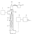
図1の構成図に示すように、この半導体排ガス通路のクリーニング方法では、たとえば半導体製造装置1の排ガスを流通させる排ガス通路2の屈曲部3に当該排ガス通路3の内面に付着する付着物を除去する半導体排ガス通路クリーニング装置4が予め付設されている。
【0062】
この半導体排ガス通路クリーニング装置4は、前記屈曲部3の内面に接して回転する回転ブラシからなる清掃具5と、この清掃具5を回転させる自動操作手段とを備え、この自動操作手段は、前記清掃具5を駆動する電動機からなる駆動手段6と、この駆動手段6を制御する制御手段7とを備えている。
【0063】
この制御手段7は、タイマーを内蔵し、たとえば148時間(1週間)ごとに10〜20分間にわたって駆動手段6を運転させる。
【0064】
この148時間内に半導体製造装置1から排出される排ガスよりたとえば二酸化珪素などの付着物が生成し、前記屈曲部3の内面に付着するが、その付着量は最大でも所定量よりも少なく、前記清掃具5を回転させると簡単に排ガス通路の内面から剥離し、排ガス通路2内に舞い上がる。
【0065】
そして、排ガス通路2内に舞い上がった付着物は粉塵となって、排ガス通路2内を流れる排ガスの流れに乗って下流に排出される。
【0066】
なお、排ガス中には有害ガスが含まれていることがあるのであり、又、排ガスに乗せて排出する粉塵の中には有害物質や、大気中の酸素や水分と反応して燃焼する物質や、大気中の酸素や水分と反応して有害ガスを発生する物質が含まれていることがあるので、排ガス通路2の終端には有害ガスを無害化する無害化処理装置8と粉塵除去装置9とが接続され、無害化処理装置8で有害ガスを無害化し、更に、粉塵除去装置9で排ガス中の粉塵を除去してから排ガスを大気中に放出している。
【0067】
上述したように、この半導体排ガス通路クリーニング装置4を排ガス通路2の屈曲部3に予め設置して、屈曲部3内面の付着物の付着量が所定量に成長する前に、定期的にこの半導体排ガス通路クリーニング装置4を作動させれば、排ガス通路2を取り外さずにその要所(ここでは屈曲部3)の内面をクリーニングできる。
【0068】
従って、クリーニングを実施するために、半導体製造装置1を停止させて、排ガス通路2内の排ガスをパージする必要もなくなり、半導体製造装置1を稼動させながら、前記屈曲部3の内面をクリーニングすることができる結果、クリーニングのために半導体製造装置1の稼動率を低下させずに済むのである。
【0069】
又、このクリーニング方法によれば、屈曲部3内面の付着物の付着量が所定量に成長する前に、定期的にこの半導体排ガス通路クリーニング装置4を作動させてクリーニングするので、排ガス通路2の前記屈曲部3の内面に所定量以上の付着物が付着するおそれがなくなり、付着物によって排ガスの流れが妨げられたり、排ガス通路2が閉塞されたりするおそれを確実になくすことができるのである。
【0070】
更に、排ガス通路2のクリーニングのために半導体製造装置1を停止させたり、排ガス通路2内の排ガスをパージしたり、排ガス通路を着脱したりしないので、半導体製造装置1の稼動率を低下させることなくクリーニングを実施するために特別の日、たとえば工場休業日などを選定する必要がなくなり、日程的にクリーニングの回数が制限されることはないから、屈曲部3内面の付着物の付着量が所定量に成長する前に、確実にクリーニングをして、排ガス通路2の前記屈曲部3の内面に所定量以上の付着物が付着するおそれを一層確実になくすることができる。
【0071】
しかも、このクリーニング方法によれば、クリーニングのために排ガス通路2を取り外す必要がないので、排ガス通路2内の付着物が大気中の酸素や水分に触れて爆発的に反応したり、燃焼して有害ガスを発生したりするおそれがなくなり、作業の安全性が一層高められるのである。
【0072】
なお、この実施例では、清掃具5を回転させて屈曲部3内面のクリーニングを行っているが、清掃具5が回転せずに屈曲部3の上流側と下流側とにわたって往復移動して屈曲部3内面を掃くようにしたり、清掃具5が回転しながら屈曲部3の上流側と下流側とにわたって往復移動して屈曲部3内面を掃くようにしたりしてもよい。
【0073】
加えて、このクリーニング方法によれば、排ガス通路2より舞い上がらせた付着物が排ガス通路2内を流れる気流によって無害化処理装置8に運ばれて無害化され、更に粉塵除去装置9で集塵されるので、排ガス通路2より除去した付着物が周囲に飛散されることなく安全に粉塵除去装置9で回収されることになる。
【0074】
図2の構成図に示す排ガス通路クリーニング装置10は、排ガス通路2の直線部分11内に配置される長さ1〜数mのはたき12と、このはたき12を操作する操作手段13とを備える。
【0075】
この操作手段13は、電動モーターからなる駆動手段14と、これを制御する制御手段15とを備え、前記駆動手段14の出力軸に接続具16を介して当該はたき12の上端部が連結される。
【0076】
前記制御手段15にはタイマーが内蔵され、前例と同様に、たとえば148時間(1週間)ごとに10〜20分間にわたって駆動手段14を運転させ、
【0077】
前記はたき12を回転させて、直線部分11の内面をこのはたき12ではたくようにしている。これにより、直線部分11の内面に付着していた付着物ははたき出されて排気通路2内に舞い上がり、更に、排ガスの流れに乗って下流に排出される。
【0078】
この半導体排ガス通路クリーニング装置10を用いる本発明第2方法の一実施例では、予めこの半導体排ガス通路クリーニング装置10が排ガス通路2の合流する直線部分11に付設され、この直線部分11の内面の付着物が所定量以上に成長する前の所定の周期、段階で前記半導体排ガス通路クリーニング装置10を作動させ、直線部分11の内面をはたいて前記付着物を直線部分11内に舞い立たせ、排ガスに乗せて下流側に排出するので、前例と同様の結果を得ることができる。
【0079】
図3の構成図に示す本発明の半導体排ガス通路クリーニング装置17は、チューブからなるはたき18と、このはたき18を操作する操作手段19とを備え、この操作手段19として、はたき18の内部にたとえば窒素ガスなどの不活性ガスを供給する不活性ガス供給手段20と、この不活性ガス供給手段20のガス供給路21に介在させた電磁弁22と、この電磁弁22を開閉させる制御手段23とが設けられている。
【0080】
この制御手段23でたとえば148時間ごとに10〜20分間にわたって電磁弁22を開弁させると、不活性ガス供給手段20から加圧された不活性ガスがはたき(チューブ)18の上端に吹き込まれ、この不活性ガスがはたき18の下端から噴出する反動ではたき18が排ガス通路の合流する直線部分11内で踊り、直線部分11の内面を激しくはたくように構成されている。
【0081】
その他の構成は図2に示す前例と同様であり、はたき18の操作方法を除いては前例と同じクリーニング方法が実施される。
【0082】
図4の構成図に示す半導体排ガス通路クリーニング装置24は、排ガス通路2の折曲部分である直線部分11の周壁に固定したバイブレータからなる加振装置25と、この加振装置25を操作する操作手段26とを備え、この操作手段26により加振装置25をたとえば148時間ごとに10〜20分間にわたり作動させて、前記直線部分11の周壁を振動させることにより、直線部分11の内面の付着物を舞い立たせ、直線部分11を流れる排ガスの流れに乗せて下流に排出するようにしている。
【0083】
この半導体排ガス通路のクリーニング方法は、排ガス通路2の直線部分11に予めこの半導体排ガス通路クリーニング装置24を付設し、直線部分11の内面に所定量以上の付着物が付着する前にこの半導体排ガス通路クリーニング装置24を作動させて、前記直線部分11の周壁を振動させることにより、直線部分11の内面の付着物を舞い上がらせ、前記直線部分11を流れる排ガスの流れに乗せて下流に排出する。
【0084】
従って、このクリーニング方法によれば、排ガス通路2を取り外さずに直線部分11のクリーニングが実施できるので、上述の各例と同様の結果を得ることができる。
【0085】
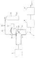
図5の構成図に示す半導体排ガス通路クリーニング装置26は、排ガス通路2の屈曲部3の内面にたとえば窒素ガスなどの不活性ガスを吹付ける流体噴射装置27を備える。
【0086】
この流体噴射装置27は、屈曲部3の内面に吹付ける不活性ガスを方向付けるノズル28と、このノズル28に窒素ガスなどの不活性ガスを供給する不活性ガス供給装置29とを備える。
【0087】
この不活性ガス供給装置29の配管30には電磁弁31を介在させてあり、操作手段32により、たとえば148時間ごとに10〜20分間にわたり電磁弁31を開弁させ、加圧された窒素ガスをノズル28から屈曲部3の内面に吹付け、この屈曲部3の内面から付着物を吹き飛ばして屈曲部3内に舞い上がらせ、排ガスの流れに乗せて下流側に排出する。
【0088】
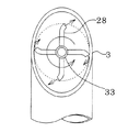
図6の断面図に示すように、前記ノズル28は、旋回継手33を介して屈曲部3の軸心回りに回転可能に配置され、このノズル28より屈曲部3の内面に対して傾斜する方向に噴射する不活性ガスの反動で回転して、屈曲部3の内面の全周にわたって均等に不活性ガスを吹付けるように構成している。
【0089】
この半導体排ガス通路のクリーニング方法は、排ガス通路2の屈曲部3にこの半導体排ガス通路クリーニング装置26を予め設けておき、この屈曲部3の内面の付着物が所定量以上に成長する前の148時間ごとに10〜20分間にわたりこの半導体排ガスクリーニング装置26を作動させて、屈曲部3の内面より付着物を舞い上がらせ、排ガスの流れに乗せて下流側に排出するので、このクリーニング方法によれば、排ガス通路2を取り外すことなく屈曲部3のクリーニングができる作用を得ることができるので、上述の各例と同様の結果を得ることができる。
【0090】
なお、この半導体排ガス通路クリーニング装置26において、図7の構成図及び図8の断面図に示すように、ノズル28にブラシからなる清掃具34を支持させ、ノズル28の回転に伴ってこの清掃具34で屈折部3内面から付着物を掃き取ると同時に、不活性ガスで屈曲部3内面から付着物を吹き飛ばすようにしてもよい。
【0091】
この場合、ノズル28を二段式或いは三段式等の複数段の出没自在に構成し(例えば、いわゆる振り出し竿のような構造)、ノズル28が、停止しているときは中ノズル(図示せず)が基幹ノズル内にバネ付勢によって収納されて短く、従って、排ガスの流通には障害とならず、一方、回転しているときは遠心力で中ノズルが突出して排ガス通路の内面に接触するように構成しても良いのである。
【0092】
【発明の効果】
以上に説明したように、本発明装置は、粉塵発生源、例えば半導体製造装置から排出される排ガスを流通させる排ガス通路の要所の内面を清掃する清掃具と、この清掃具を操作する操作手段とを備えるので、予めこの本発明装置を前記排ガス通路に設置しておき、排ガス通路内面の付着物が所定量以上に成長する前にこの本発明装置を作動させることにより、付着物を排ガス通路内面より剥離、除去して排ガス通路内に舞い上がらせ、これを排ガス通路内の気流に乗せて下流側に排出することができる効果を奏するのである。
【0093】
そして、本発明装置において、粉塵発生源、例えば半導体製造装置から排出される排ガスを流通させる排ガス通路の要所の内面を掃き出す清掃具と、この清掃具を操作する操作手段とを備えた場合、予めこの装置を前記排ガス通路に設置しておき、排ガス通路内面の付着物が所定量以上に成長する前にこの装置を作動させることにより、付着物を排ガス通路内面より剥離、除去して排ガス通路内に舞い上がらせ、これを排ガス通路内の気流に乗せて下流側に排出することができる効果を奏するのである。
【0094】
又、本発明装置は、粉塵発生源、例えば半導体製造装置の排ガスを流通させる排ガス通路の直線部分の内面をはたくはたきと、このはたきを操作する操作手段とを備えるので、予めこの本発明装置を前記排ガス通路に設置しておいて、排ガス通路内面の付着物が所定量以上に成長する前にこの本発明装置を作動させることにより、付着物を排ガス通路内面よりはたき出して排ガス通路内に舞い上がらせ、これを排ガス通路内の気流に乗せて下流側に排出することができる効果を奏するのである。
【0095】
更に、本発明装置において、粉塵発生源、例えば半導体製造装置から排出される排ガスを流通させる排ガス通路の要所の内面を振動させる加振装置を備えた場合、予めこの装置を前記排ガス通路に設置しておき、排ガス通路内面の付着物が所定量以上に成長する前にこの装置を作動させることにより、付着物を排ガス通路内面より振い出して排ガス通路内に舞い上がらせ、これを排ガス通路内の気流に乗せて下流側に排出することができる効果を奏するのである。
【0096】
又、本発明装置において、粉塵発生源、例えば半導体製造装置から排出される排ガスを流通させる排ガス通路の要所の内面に流体を吹付ける流体噴射装置を備えた場合、予めこの装置を前記排ガス通路に設置しておき、排ガス通路内面の付着物が所定量以上に成長する前にこの本発明第4装置を作動させることにより、付着物を排ガス通路内面より吹き飛ばして排ガス通路内に舞い上がらせ、これを排ガス通路内の気流に乗せて下流側に排出することができる効果を奏するのである。
【0097】
このように、本発明装置を予め排ガス通路に設置しておき、排ガス通路内面の付着物が所定量以上に成長する前にこの本発明装置を作動させることにより、付着物を排ガス通路内面より剥離、除去して排ガス通路内に舞い上がらせ、これを排ガス通路内の気流に乗せて下流側に排出する本発明方法を実施することができる。
【0098】
そして、本発明方法は、粉塵発生源、例えば半導体製造装置の排ガスを流通させる排ガス通路の要所に該排ガス通路の内面に付着する付着物を除去する排ガス通路クリーニング装置、例えば半導体排ガス通路クリーニング装置を予め付設しておき、その排ガス通路の要所内面の付着物が所定量に成長する前に、この半導体排ガス通路クリーニング装置を作動させて付着物を排ガス通路内に舞い上がらせ、これを排ガス通路内を流れる気流に乗せて下流側に排出するので、本発明方法によれば、排ガス通路を取り外すことなく排ガス通路の要所のクリーニングを実施できる、という効果を得ることができる。
【0099】
従って、本発明方法によれば、排ガス通路のクリーニングのために粉塵発生源、例えば半導体製造装置を停止させ、排ガス通路の排ガスをパージする必要はなくなり、粉塵発生源、例えば半導体製造装置の稼動中でも排ガス通路のクリーニングを実施することができる、という効果も得ることができる。
【0100】
その結果、本発明方法によれば、排ガス通路のクリーニングのために粉塵発生源、例えば半導体製造装置の稼動率が低下するおそれがなくなり、又、粉塵発生源、例えば半導体製造装置の稼動率を下げずにクリーニングを行う上での日程的な制限がなくなり、必要な頻度でクリーニングを実施して、付着物が排ガスの流れを妨げたり、排ガス通路を閉塞したりすることを確実に防止することができるなどの効果も得ることができる。
【0101】
更に、本発明方法によれば、クリーニングのために排ガス通路を脱着しないので、例えば半導体製造装置の停止、排ガス通路内の排ガスのパージ、排ガス通路の取り外し、クリーニング装置の挿入などのクリーニングを実施する前の準備作業や、クリーニング装置の取り出し、排ガス通路の取り付け、排ガス通路内のエアパージなどのクリーニング終了後の事後処理作業が不要になり、人手と時間を節約できる、という効果も得ることができる。
【0102】
又更に、本発明方法によれば、クリーニングのために排ガス通路を脱着しないので、付着物が大気と接触して爆発的に反応したり、燃焼して有害ないし危険なガスを発生したりするおそれがなくなり、安全性が高められる、という効果も得ることができる。
【0103】
加えて、本発明方法によれば、排ガス通路より舞い上がらせた付着物が排ガス通路内の気流に乗って下流側に排出されるので、排ガス通路の下流に集塵装置を接続して、排ガス通路から除去された付着物を周囲に飛散させることなく安全に回収することができる、という効果も得ることができる。
【図面の簡単な説明】
【図1】図1は本発明第1装置の構成図である。
【図2】図2は本発明第2装置の構成図である。
【図3】図3は本発明第2装置の他例を示す構成図である。
【図4】図4は本発明第3装置の構成図である。
【図5】図5は本発明第4装置の構成図である。
【図6】図6は図5のA−A線断面図である。
【図7】図7は本発明第4装置の他例を示す構成図である。
【図8】図8は図7のB−B線断面図である。
【符号の説明】
1 半導体製造装置
2 排ガス通路
4 半導体排ガス通路クリーニング装置
5 清掃具
6 駆動手段
7 制御手段
10 半導体排ガス通路クリーニング装置
12 はたき
15 操作手段
17 半導体排ガス通路クリーニング装置
18 はたき(チューブ)
23 操作手段
24 半導体排ガス通路クリーニング装置
25 加振装置
26 操作手段
27 半導体排ガス通路クリーニング装置
28 流体噴射装置[0001]
BACKGROUND OF THE INVENTION
The present invention relates to an exhaust gas passage cleaning method capable of cleaning an exhaust gas passage without stopping a dust generation source, and an exhaust gas passage cleaning device for carrying out the exhaust gas passage cleaning method according to the present invention.
[0002]
[Prior art]
Sources of dust, such as semiconductor device manufacturing industry, automobile industry, plastic industry, resource industry, ceramic industry, powder metallurgy industry, detergent industry, catalyst industry, ferrite industry, color material industry, agricultural chemical industry, feed processing industry, food industry, disposal Dust is generated in the material processing industry, bio-related industry, cosmetics industry, pharmaceutical industry, and the like.
In these dust generation sources, it is known that very fine dust having a particle size of, for example, about 0.01 to 50 μm is generated.
[0003]
In particular, recently, computers and electronic control devices to which they are applied have been strikingly developed, and the direction and scope of their development seems to be infinite.
For this reason, the manufacturing technology and production volume of semiconductor electronic elements, which occupy a major position as electronic components used in computers, are growing remarkably.
[0004]
Germanium (Ge) and silicon (Si) are frequently used as semiconductors as raw materials for these semiconductor elements, and gallium arsenide (GaAs), gallium phosphide (GaP), etc. have been put to practical use as special elements.
[0005]
Dust generated in the semiconductor device manufacturing process itself is a harmful substance that is prohibited from being released from the viewpoint of pollution prevention, the gas containing it is a harmful substance, or adsorbs a harmful substance in the atmosphere. And are adsorbed.
[0006]
Examples of harmful substances used or generated in the semiconductor manufacturing process include silicon-based, arsenic-based, phosphorus-based, boron-based, metal hydride, chlorofluorocarbon, halogen, halide, nitrogen oxide, and others.
[0007]
Since the exhaust gas from the dust generation source contains harmful components that impair human health, the exhaust gas is guided from the dust generation source to the detoxification treatment device that detoxifies the harmful components of the exhaust gas through the exhaust gas passage blocked from the outside.
[0008]
This exhaust gas contains, for example, a component that generates silicon dioxide solids by oxidation, such as monosilane gas, and a component that crystallizes due to a decrease in exhaust gas temperature, such as tungsten hexafluoride (WF6). Solid materials and crystals (hereinafter simply referred to as deposits) generated from the exhaust gas adhere to the inner surface of the exhaust gas passage, and gradually accumulate to obstruct the flow of the exhaust gas, eventually closing the exhaust gas passage. .
[0009]
Conventionally, a part or all of the exhaust gas passage is removed periodically or at an appropriate time in order to prevent the deposits on the inner surface of the exhaust gas passage from obstructing the flow of the exhaust gas or blocking the exhaust gas passage. In the exhaust gas passage, cleaning is performed by cleaning with a brush or removing the deposits using compressed air, or by performing cleaning or the like.
[0010]
In order to perform this cleaning, some or all of the exhaust gas passage must be removed, but when removing all or part of this exhaust gas passage, harmful or dangerous gases contained in the exhaust gas are not released to the surroundings. There is a need to.
[0011]
For this reason, when cleaning the exhaust gas passage, it is necessary to prepare in advance to stop the dust generation source in advance, purge the dust generation source and the exhaust gas in the exhaust gas passage, and then remove part or all of the exhaust gas passage.
[0012]
After cleaning, before restarting the dust source, remove the brush, nozzle, etc. from the exhaust gas passage, attach part or all of the exhaust gas passage, and remove the dust source and air in the exhaust gas passage. Need to purge.
The deposits removed from the inner surface of the exhaust gas passage by cleaning are collected in a suitable container.
[0013]
[Problems to be solved by the invention]
This prior art has the following problems because part or all of the exhaust gas passage is removed for cleaning the exhaust gas passage.
[0014]
First, by stopping the dust generation source for a long time, there is a problem that the operation rate of the dust generation source is reduced and the production / operation efficiency of the semiconductor is reduced.
[0015]
This problem can be solved by performing the cleaning of the exhaust gas passage on the scheduled date of stopping the dust source, such as a factory holiday, but the time required to restart the dust source after it has been stopped. Since it is long, the opportunity for cleaning is limited, and the number of cleanings is reduced.
[0016]
If the number of cleanings decreases, a large amount of deposits will adhere to the inner surface of the exhaust gas passage before the next cleaning, and the time and effort of the next cleaning will often increase, so it is necessary to estimate the cleaning work time longer. This can lead to a vicious circle in which the opportunities for cleaning can be further limited.
[0017]
Further, in the prior art, after stopping the dust generation source, purging the dust generation source and the exhaust gas in the exhaust gas passage, removing a part or all of the exhaust gas passage, cleaning the inner surface of the exhaust gas passage, It is necessary to install a cleaned exhaust gas passage and to purge the dust generation source and the air in the exhaust gas passage to clean the inner surface of the exhaust gas passage. There is a problem that it takes.
[0018]
Furthermore, among the deposits adhering to the inner surface of the exhaust gas passage, when part or all of the exhaust gas passage is removed, it reacts explosively with atmospheric oxygen and moisture flowing into the exhaust gas passage, burns, and produces harmful gases. In order to ensure the safety of the worker, a large amount of expenses are required for safety education for the worker, purchase of protective clothing, and the like.
[0019]
In addition, the treatment of the deposits removed from the exhaust gas passage is troublesome, and there is also a problem that the deposits are easily scattered around.
[0020]
The exhaust gas passage cleaning method according to the present invention (hereinafter referred to as the present invention method) eliminates such problems of the prior art and provides an exhaust gas passage cleaning method capable of cleaning the exhaust gas passage without detaching the exhaust gas passage. The purpose is to provide.
[0022]
An exhaust gas passage cleaning device according to the present invention (hereinafter referred to as the present invention device) is an exhaust gas passage cleaning device used for carrying out the method of the present invention, that is, an exhaust gas passage.Straight sectionIt is an object of the present invention to provide an exhaust gas passage cleaning device used for carrying out the method of the present invention for cleaning by hitting the inner surface.
[0025]
[Means for Solving the Problems]
In order to achieve the above object, the method of the present invention provides an exhaust gas passage for circulating exhaust gas from a dust source.Straight line partIn addition, an exhaust gas passage cleaning device that removes deposits adhering to the inner surface of the exhaust gas passage by spraying it from the tip through the compressed fluid into the tube and moving it like a whip is attached in advance to the inner surface. The exhaust gas passage cleaning device is operated at an arbitrary stage before the deposit amount of the adhering material grows to a predetermined amount or more, so that the adhering material floats up from the inner surface into the exhaust gas passage, and is placed on the airflow flowing in the exhaust gas passage The technical means is characterized by the fact that it is discharged downstream.
[0026]
According to the method of the present invention, since it is not necessary to attach or detach the exhaust gas passage, the exhaust gas passage can be cleaned without stopping the dust generation source. Further, by collecting the deposits removed from the inner surface of the exhaust gas passage to a dust collector or the like provided downstream of the exhaust gas passage, the recovery processing can be performed without being scattered around.
[0027]
Hereinafter, the method of the present invention will be described in more detail..
[0028]
By the way, for example, a gas from which impurities are highly removed is used as a raw material gas used in semiconductor manufacturing. Therefore, there is a possibility that adhering substances mixed with the raw material gas are introduced into the dust generation source and discharged into the exhaust gas passage. Absent. Therefore, the deposit on the inner surface of the exhaust gas passage is generated from the exhaust gas, and can be removed very easily as soon as it adheres to the inner surface of the exhaust gas passage. As a result, it becomes increasingly difficult to adhere to and remove the inner surface.
[0029]
According to the method of the present invention, the exhaust gas passage cleaning device can be operated at an arbitrary stage before the amount of deposits on the inner surface of the exhaust gas passage grows to a predetermined amount or more. The kimono can be swollen from the inner surface of the exhaust gas passage into the exhaust gas passage, and the deposits that have risen in the exhaust gas passage have not grown greatly. It can be discharged. Of course, in the method of the present invention, the exhaust gas passage cleaning device is generally intermittently operated, but it does not prevent continuous operation instead.
[0030]
In the method of the present invention, as a method of causing deposits to rise from the inner surface of the exhaust gas passage, The exhaust gas passage cleaning device is activated and knocked out.For exampleAboveMethod of sweeping out deposits on the inner surface by operating the exhaust gas passage cleaning device (sweeping out),A method of vibrating the exhaust gas passage cleaning device to vibrate the inner surface of the exhaust gas passage (vibration), A method of operating the exhaust gas passage cleaning device to spray fluid onto the inner surface of the exhaust gas passage and blow off deposits (blow off)Such asYou may use a method together.
[0031]
Scavenging deposits from the inner surface of the exhaust gas passageMethodIs a method of sliding the cleaning tool against the inner surface,A cleaning tool that sweeps the inner surface of the main part of the exhaust gas passage through which the exhaust gas discharged from the dust source is circulated, and an operating means for operating the cleaning tool.Prepare.
[0032]
Here, the cleaning tool is a tool that slides on the inner surface to peel off the deposits from the inner surface, and examples thereof include a brush and a mop.
[0033]
The brush bristles and mop tufts are made of metal such as stainless steel, Teflon resin, PVC resin, polyimide, polyamide (nylon), aromatic polyamide (aramid resin), polyester, and other engineering plastics. Can be used.
[0034]
In addition to brushes and mops, cleaning tools also include natural or synthetic polymer materials including metal and rubber, and spatulas (blades) made of polymer materials and wood.
[0035]
or,Cleaning toolThe operating means includes a manual operating means and an automatic operating means. The automatic operating means is provided with a driving means for driving the cleaning tool and a control means for controlling the driving means.
[0036]
Typical examples of the driving means include a rotation driving means for rotating the cleaning tool and a linear reciprocating driving means for linearly reciprocating the cleaning tool. The rotation driving means rotates the cleaning tool in one direction. There are two types, one for rotating the cleaning tool within a predetermined angle range, and examples of the former include an electric motor, a hydraulic motor, and an air motor. In addition, it is possible to use an internal combustion engine, but there are problems in noise and ease of control.
[0037]
Examples of the latter, that is, the driving means for reciprocatingly rotating the cleaning tool within a predetermined range include an oscillator in which an output shaft such as a hydraulic oscillator or an air oscillator reciprocates within a predetermined range. A rotating machine such as a motor can be reciprocally rotated within a predetermined angle range, or the cleaning tool can be reciprocated within a predetermined range by combining the above rotating machine with a cam mechanism, a link, or the like. Is possible.
[0038]
Examples of linear reciprocating drive means for reciprocating the cleaning tool in the axial direction of the exhaust gas passage within a predetermined range include solenoids, hydraulic cylinders, air cylinders, electric cylinders, linear motors, etc. It is also possible to use a combination of the rotating machine and a motion conversion mechanism that converts a rotary motion such as a slider-crank mechanism and a cam mechanism into a reciprocating motion.
[0039]
Of course, as the driving means, it is possible to use a cleaning tool configured to reciprocate within a predetermined range in the axial direction of the exhaust gas passage and to rotate around the axis.
[0040]
The method of the present invention, that is, the method of the present invention in which the exhaust gas passage cleaning device is operated to eject deposits from the inner surface of the exhaust gas passage.Straight sectionIn order to carry out the method of the present invention, an exhaust gas passage cleaning device according to the present invention is a method of exhaust gas passage through which exhaust gas from a dust source is circulated.Straight line partThe technical means is characterized in that it is provided with a hitting of the inner surface and an operating means for operating the hitting.
[0041]
As this beatingUsedtubeIsLike a whip that is injected from the tip through compressed fluid (compressed nitrogen gas, compressed carbon dioxide gas, compressed air, pressurized liquid, etc.)Moved.
[0042]
As this drive means,Provided with compressed air supply means for supplying compressed air to one end of a firewood made of a tube having one end fixed at a predetermined position in the exhaust gas passageTheCan be mentioned.
[0043]
Add vibration to the inner surface of the exhaust gas passageIn the method,A vibration device that vibrates the inner surface of the main part of the exhaust gas passage that distributes the exhaust gas discharged from the dust source.Prepare.
[0044]
Examples of the vibration device include a device provided with a hammer that strikes the inner surface or outer surface of the exhaust gas passage, and a vibrator that generates mechanical vibration.
[0045]
Next, the fluid is sprayed on the inner surface of the exhaust gas passage to blow off the deposits from the inner surface.MethodThe fluid used in the above includes a compressed liquid, a compressed gas, or a mixture of two or more of these, but from the viewpoint of simplifying the post-treatment, it is directly diffused into the atmosphere along with the exhaust gas. It is preferable to use a gas that can be used, and in view of disaster prevention, it is more preferable to use a dry inert gas.
[0046]
The method of spraying fluid on the inner surface of the exhaust gas passage is broadly divided into a method of spraying fluid at right angles to the inner surface and a method of spraying fluid obliquely on the inner surface, and the latter is against the flow of exhaust gas. A method of spraying in a direction, a method of spraying in a direction to give a rotating component rotating around the axis of the exhaust gas passage to the flow of exhaust gas, a method of spraying in a direction of accelerating the flow of exhaust gas, the axis of the exhaust gas passage in the flow of exhaust gas A method of spraying in a direction that counteracts the flow of exhaust gas while giving a rotating component that rotates around, a method of spraying in a direction that accelerates the flow of exhaust gas while giving a rotational component that rotates around the axis of the exhaust gas passage to the flow of exhaust gas, etc. Is mentioned.
[0047]
Among these methods, it is preferable to employ a method that does not hinder the emission of exhaust gas, and it is more preferable to employ a method that can further promote the emission of exhaust gas. That is, the most preferable method is to apply a rotating component that rotates around the axis of the exhaust gas passage to the exhaust gas flow and spray the exhaust gas in a direction that accelerates the exhaust gas flow.
[0048]
by the way,Method of spraying fluid from the inner surface by spraying fluid on the inner surface of the exhaust gas passageTo carry outInvention deviceIs a fluid injection device that sprays fluid on the inner surface of the main point of the exhaust gas passage for circulating the exhaust gas discharged from the dust source.Prepare.
[0049]
The fluid ejecting apparatus includes a nozzle for directing a fluid to be sprayed on the inner surface of the exhaust gas passage, and a fluid supply device for supplying fluid to the nozzle. The nozzle is fixedly installed in the exhaust gas passage and moved. Although it may be installed in some cases, from the viewpoint of spraying fluid evenly on the inner surface of the exhaust gas passage, it is preferably provided so as to be movable in the exhaust gas passage.
[0050]
That is, the nozzle is provided so as to rotate around the axis of the exhaust gas passage in the exhaust gas passage, or provided to be movable along the axis of the exhaust gas passage in the exhaust gas passage, or within the exhaust gas passage. It is preferable to provide rotation around the axis and move along the axis of the exhaust gas passage.
[0051]
In the bent portion of the exhaust gas passage, the nozzle can be provided on the bent surface so as to be rotatable around the central axis of the bent surface.
[0052]
This nozzle may be rotated manually, or may be rotated using a driving means such as a motor. However, in order to reduce the number of parts and save energy consumption, the reaction of the fluid is used. It is preferable to do.
[0053]
That is, a method of spraying the exhaust gas flow in a direction that gives a rotating component that rotates around the axis of the exhaust gas passage, or a direction that applies a rotating component that rotates around the axis of the exhaust gas channel to the exhaust gas flow and opposes the flow of the exhaust gas Or by applying a rotational component that rotates around the axis of the exhaust gas passage to the exhaust gas flow and in a direction that accelerates the exhaust gas flow. It is preferable to rotate around the axis of the exhaust gas passage.
[0054]
As a method of moving the nozzle in the axial direction of the exhaust gas passage, there are a manual operation method and an automatic operation method. Examples of the automatic operation method include solenoids, hydraulic cylinders, air cylinders, electric cylinders, linear motors, etc. There are a method using a linear reciprocating drive means and a method using a rotary drive means such as an electric motor and a motion conversion mechanism for converting a rotary motion such as a slider-crank mechanism and a cam mechanism into a reciprocating motion.
[0055]
[Action]
As described above, the method of the present invention is used in the exhaust gas passage for circulating the exhaust gas from the dust source.Straight line partIn addition, an exhaust gas passage cleaning device that removes deposits adhering to the inner surface of the exhaust gas passage by spraying it from the tip through the compressed fluid into the tube and moving it like a whip is attached in advance to the inner surface. The exhaust gas passage cleaning device is operated at an arbitrary stage before the deposit amount of the adhering material grows to a predetermined amount or more, so that the adhering material floats up from the inner surface into the exhaust gas passage, and is placed on the airflow flowing in the exhaust gas passage. Therefore, according to the method of the present invention, it is not necessary to remove the exhaust gas passage for cleaning the exhaust gas passage.
[0056]
Further, according to the method of the present invention, it is not necessary to remove the exhaust gas passage in order to carry out the cleaning of the exhaust gas passage. Therefore, it is necessary to stop the dust generation source prior to cleaning and purge the exhaust gas from the dust generation source and the exhaust gas passage. The effect of disappearing is obtained.
[0057]
Furthermore, according to the method of the present invention, it is not necessary to remove the exhaust gas passage in order to carry out the cleaning of the exhaust gas passage, so it is not necessary to assemble the exhaust gas passage after cleaning and purge the dust generation source and the air in the exhaust gas passage, The effect that cleaning can be performed even when the dust generation source is in operation is obtained.
[0058]
Furthermore, according to the method of the present invention, since it is not necessary to remove the exhaust gas passage in order to carry out the cleaning of the exhaust gas passage, there is no possibility that harmful gases and deposits in the exhaust gas passage come into contact with the atmosphere during cleaning. It is also possible to obtain an effect of increasing
[0059]
In addition, according to the method of the present invention, the deposits that have risen from the inner surface of the exhaust gas passage are discharged to the downstream side on the airflow flowing in the exhaust gas passage, so that the deposits are deposited on the dust collector connected downstream of the exhaust gas passage. Thus, it is possible to collect the deposits, and it is also possible to collect the deposits safely without scattering them.
[0060]
BEST MODE FOR CARRYING OUT THE INVENTION
In the following description of the present invention, in the present embodiment, the dust generation source is a semiconductor manufacturing apparatus. Accordingly, a method for cleaning a semiconductor exhaust gas passage and a semiconductor cleaning apparatus for implementing the method are specifically described with reference to the drawings. explain.
[0061]
As shown in the configuration diagram of FIG. 1, in this method for cleaning a semiconductor exhaust gas passage, for example, deposits adhering to the inner surface of the
[0062]
The semiconductor exhaust gas passage cleaning device 4 includes a
[0063]
This control means 7 has a built-in timer and operates the drive means 6 for 10 to 20 minutes every 148 hours (one week), for example.
[0064]
During this 148 hours, deposits such as silicon dioxide are generated from the exhaust gas discharged from the
[0065]
The deposits that have risen into the
[0066]
In addition, the exhaust gas may contain harmful gases, and among the dust discharged on the exhaust gas, there are harmful substances, substances that react with oxygen and moisture in the atmosphere and burn Since substances that react with oxygen and moisture in the atmosphere to generate harmful gases may be included, the end of the
[0067]
As described above, the semiconductor exhaust gas passage cleaning device 4 is installed in the
[0068]
Therefore, it is not necessary to stop the
[0069]
Further, according to this cleaning method, the semiconductor exhaust gas passage cleaning device 4 is periodically operated and cleaned before the amount of deposits on the inner surface of the
[0070]
Furthermore, the
[0071]
In addition, according to this cleaning method, it is not necessary to remove the
[0072]
In this embodiment, the
[0073]
In addition, according to this cleaning method, the deposits that have risen from the
[0074]
In the configuration diagram of FIG.ShowThe exhaust gas
[0075]
The operation means 13 includes a drive means 14 composed of an electric motor and a control means 15 for controlling the drive means 14, and the upper end of the
[0076]
The control means 15 has a built-in timer, and as in the previous example, for example, the drive means 14 is operated for 10 to 20 minutes every 148 hours (1 week),
[0077]
The
[0078]
In an embodiment of the second method of the present invention using this semiconductor exhaust gas
[0079]
As shown in the block diagram of FIG.Of the present inventionThe semiconductor exhaust gas
[0080]
For example, when the
[0081]
The other configuration is the same as that of the previous example shown in FIG. 2, and the same cleaning method as that of the previous example is performed except for the operation method of the
[0082]
In the configuration diagram of FIG.ShowThe semiconductor exhaust gas passage cleaning device 24 includes a
[0083]
thisThe semiconductor exhaust gas passage cleaning method is performed by attaching the semiconductor exhaust gas passage cleaning device 24 to the
[0084]
Therefore, according to this cleaning method, the
[0085]
In the configuration diagram of FIG.ShowThe semiconductor exhaust gas
[0086]
The
[0087]
A
[0088]
As shown in the cross-sectional view of FIG. 6, the
[0089]
thisIn the semiconductor exhaust gas passage cleaning method, the semiconductor exhaust gas
[0090]
In the semiconductor exhaust gas
[0091]
In this case, the
[0092]
【The invention's effect】
As described above, the device according to the present invention includes a cleaning tool for cleaning the inner surface of a main part of an exhaust gas passage through which exhaust gas discharged from a dust generation source, for example, a semiconductor manufacturing apparatus, and an operating means for operating the cleaning tool. Therefore, the apparatus of the present invention is installed in the exhaust gas passage in advance, and the apparatus of the present invention is operated before the deposit on the inner surface of the exhaust gas passage grows to a predetermined amount or more. It peels and removes from the inner surface, so that it floats up in the exhaust gas passage, and this can be carried on the airflow in the exhaust gas passage and discharged downstream.
[0093]
AndIn the device of the present invention,A dusting source, for example, a cleaning tool that sweeps out the inner surface of the main part of the exhaust gas passage through which the exhaust gas discharged from the semiconductor manufacturing apparatus circulates, and an operating means for operating the cleaning tool.If you haveThis in advanceapparatusIs installed in the exhaust gas passage, and before the deposit on the inner surface of the exhaust gas passage grows beyond a predetermined amount,apparatusAs a result, the deposits are peeled off and removed from the inner surface of the exhaust gas passage so as to rise in the exhaust gas passage, and this can be carried on the air flow in the exhaust gas passage and discharged downstream.
[0094]
In addition, the device of the present invention has a dust generation source, for example, an exhaust gas passage for circulating the exhaust gas of a semiconductor manufacturing device.Straight line partSince the present invention apparatus is installed in the exhaust gas passage in advance, the deposit on the inner surface of the exhaust gas passage grows to a predetermined amount or more. By operating this apparatus of the present invention, the deposits are ejected from the inner surface of the exhaust gas passage, so as to rise in the exhaust gas passage, and this can be carried on the air flow in the exhaust gas passage and discharged downstream. is there.
[0095]
Furthermore,In the device of the present inventionA vibration generator that vibrates the inner surface of the main part of the exhaust gas passage through which the exhaust gas discharged from the dust production source, for example, the semiconductor manufacturing apparatus flows.When equipped, This in advanceapparatusIs installed in the exhaust gas passage, and before the deposit on the inner surface of the exhaust gas passage grows beyond a predetermined amount,apparatusAs a result, the deposits are swung out from the inner surface of the exhaust gas passage so as to rise in the exhaust gas passage, and this can be carried on the air flow in the exhaust gas passage and discharged downstream.
[0096]
or,In the device of the present inventionA fluid ejection device that sprays fluid onto the inner surface of a main part of an exhaust gas passage through which exhaust gas discharged from a dust generation source, for example, a semiconductor manufacturing apparatus flows.When equipped, This in advanceapparatusIs installed in the exhaust gas passage, and the deposit is blown off from the inner surface of the exhaust gas passage by operating the fourth device of the present invention before the deposit on the inner surface of the exhaust gas gas grows to a predetermined amount or more. This brings about the effect that it can be swung up and discharged to the downstream side on the airflow in the exhaust gas passage.
[0097]
As described above, the apparatus of the present invention is installed in the exhaust gas passage in advance, and the deposit is peeled off from the inner surface of the exhaust gas passage by operating the apparatus of the present invention before the deposit on the inner surface of the exhaust gas grows to a predetermined amount or more. It is possible to carry out the method of the present invention in which it is removed and floated up in the exhaust gas passage, and this is placed on the air flow in the exhaust gas passage and discharged downstream.
[0098]
Then, the method of the present invention is an exhaust gas passage cleaning device, for example, a semiconductor exhaust gas passage cleaning device, which removes deposits adhering to the inner surface of the exhaust gas passage to a dust generation source, for example, an exhaust gas passage through which the exhaust gas of a semiconductor manufacturing apparatus flows. Before the deposit on the inner surface of the important point of the exhaust gas passage grows to a predetermined amount, this semiconductor exhaust gas passage cleaning device is operated to cause the deposit to rise into the exhaust gas passage. Since it discharges | emits downstream in the airflow which flows through the inside, according to this invention method, the effect that cleaning of the important part of an exhaust gas passage can be implemented, without removing an exhaust gas passage can be acquired.
[0099]
Therefore, according to the method of the present invention, it is not necessary to stop the dust generation source, for example, the semiconductor manufacturing apparatus, and purge the exhaust gas in the exhaust path for cleaning the exhaust gas passage, and the dust generation source, for example, the semiconductor manufacturing apparatus is in operation. The effect that the exhaust gas passage can be cleaned can also be obtained.
[0100]
As a result, according to the method of the present invention, there is no risk that the operating rate of the dust generation source, for example, the semiconductor manufacturing apparatus, will decrease due to the cleaning of the exhaust gas passage, and the operating rate of the dust generation source, for example, the semiconductor manufacturing apparatus, is reduced. Without any schedule restrictions on cleaning, and cleaning can be performed as often as necessary to reliably prevent deposits from blocking the exhaust gas flow or blocking the exhaust gas passage. The effect of being able to do it can also be acquired.
[0101]
Furthermore, according to the method of the present invention, since the exhaust gas passage is not desorbed for cleaning, cleaning such as stopping the semiconductor manufacturing apparatus, purging the exhaust gas in the exhaust gas passage, removing the exhaust gas passage, and inserting the cleaning device is performed. Post-processing work after completion of cleaning, such as preparatory work, removal of the cleaning device, attachment of the exhaust gas passage, and air purge in the exhaust gas passage, is not necessary, and the effect of saving manpower and time can be obtained.
[0102]
Still further, according to the method of the present invention, the exhaust gas passage is not desorbed for cleaning, so that the deposits may react explosively with the atmosphere or may burn and generate harmful or dangerous gases. And the safety can be improved.
[0103]
In addition, according to the method of the present invention, the deposits that have risen from the exhaust gas passage ride on the airflow in the exhaust gas passage and are discharged downstream, so that a dust collector is connected downstream of the exhaust gas passage, It is also possible to obtain an effect that the deposits removed from the container can be safely collected without being scattered around.
[Brief description of the drawings]
FIG. 1 is a block diagram of a first apparatus of the present invention.
FIG. 2 is a block diagram of a second apparatus of the present invention.
FIG. 3 is a block diagram showing another example of the second device of the present invention.
FIG. 4 is a block diagram of a third device of the present invention.
FIG. 5 is a block diagram of a fourth device of the present invention.
6 is a cross-sectional view taken along line AA in FIG. 5. FIG.
FIG. 7 is a block diagram showing another example of the fourth device of the present invention.
8 is a cross-sectional view taken along the line BB of FIG.
[Explanation of symbols]
1 Semiconductor manufacturing equipment
2 Exhaust gas passage
4 Semiconductor exhaust gas passage cleaning device
5 Cleaning tools
6 Driving means
7 Control means
10 Semiconductor exhaust gas passage cleaning device
12 Hataki
15 Operating means
17 Semiconductor exhaust gas passage cleaning device
18 Hataki (tube)
23 Operating means
24 Semiconductor exhaust gas passage cleaning device
25 Exciter
26 Operating means
27 Semiconductor exhaust gas passage cleaning device
28 Fluid ejection device
Claims (2)
Priority Applications (1)
| Application Number | Priority Date | Filing Date | Title |
|---|---|---|---|
| JP2000389119A JP4642995B2 (en) | 2000-12-21 | 2000-12-21 | Exhaust gas passage cleaning method and apparatus |
Applications Claiming Priority (1)
| Application Number | Priority Date | Filing Date | Title |
|---|---|---|---|
| JP2000389119A JP4642995B2 (en) | 2000-12-21 | 2000-12-21 | Exhaust gas passage cleaning method and apparatus |
Publications (2)
| Publication Number | Publication Date |
|---|---|
| JP2002186925A JP2002186925A (en) | 2002-07-02 |
| JP4642995B2 true JP4642995B2 (en) | 2011-03-02 |
Family
ID=18855736
Family Applications (1)
| Application Number | Title | Priority Date | Filing Date |
|---|---|---|---|
| JP2000389119A Expired - Fee Related JP4642995B2 (en) | 2000-12-21 | 2000-12-21 | Exhaust gas passage cleaning method and apparatus |
Country Status (1)
| Country | Link |
|---|---|
| JP (1) | JP4642995B2 (en) |
Families Citing this family (3)
| Publication number | Priority date | Publication date | Assignee | Title |
|---|---|---|---|---|
| KR100838727B1 (en) * | 2002-08-02 | 2008-06-16 | 주식회사 포스코 | Foreign material removal device of duct bend |
| CN103091090B (en) * | 2013-01-09 | 2015-03-25 | 昆山鸿志犀自动化机电设备有限公司 | Keycap drawing force testing device with cleaning mechanism |
| CN118237349B (en) * | 2024-05-28 | 2024-08-16 | 潍坊同昊建筑规划设计有限公司 | Warm general stereoplasm pipeline gas tightness detection device |
Family Cites Families (9)
| Publication number | Priority date | Publication date | Assignee | Title |
|---|---|---|---|---|
| JPS62227482A (en) * | 1986-03-31 | 1987-10-06 | 日本農薬株式会社 | Duct cleaning device |
| JPH02102772A (en) * | 1988-10-12 | 1990-04-16 | Shinzo Katayama | Pipeline cleaning nozzle |
| JPH0356395U (en) * | 1989-10-05 | 1991-05-30 | ||
| JPH05263248A (en) * | 1992-03-16 | 1993-10-12 | Hitachi Electron Eng Co Ltd | Mechanism for cleaning pipeline |
| JP3320104B2 (en) * | 1992-07-24 | 2002-09-03 | 菱電セミコンダクタシステムエンジニアリング株式会社 | Duct with self-cleaning mechanism |
| JPH0699154A (en) * | 1992-09-22 | 1994-04-12 | Tokyo Koken Kk | Cleaning device for air conditioning duct |
| JP2984525B2 (en) * | 1993-08-12 | 1999-11-29 | 東洋ハイテック株式会社 | Flexible container cleaning device |
| JPH11192462A (en) * | 1997-12-29 | 1999-07-21 | Amano Corp | Dust pipe dust cleaning device |
| JP2000015202A (en) * | 1998-06-30 | 2000-01-18 | Lion Corp | System for cleaning and sterilizing high-viscosity fluid transfer piping and method for cleaning and sterilizing high-viscosity fluid transfer piping |
-
2000
- 2000-12-21 JP JP2000389119A patent/JP4642995B2/en not_active Expired - Fee Related
Also Published As
| Publication number | Publication date |
|---|---|
| JP2002186925A (en) | 2002-07-02 |
Similar Documents
| Publication | Publication Date | Title |
|---|---|---|
| JP6545441B2 (en) | Cleaning method of torch in plasma coating plant and plasma coating plant | |
| CN104271254B (en) | For the dry ice cleaning device and method of spraying equipment | |
| JP6983781B2 (en) | Painting booths with a spray spray removal system and methods and equipment for spray spray removal | |
| CN116617802B (en) | Atmospheric pollutant treatment device and treatment method thereof | |
| JP4642995B2 (en) | Exhaust gas passage cleaning method and apparatus | |
| JP2001087676A (en) | Cleaning method and cleaning device for dry type electrostatic precipitator | |
| US12109521B2 (en) | Cleaning device and method for cleaning a filter arrangement | |
| JPH07171531A (en) | Piping maintenance robot | |
| KR20130009560A (en) | A cleaning method using dry-ice and an apparatus to be used therefor | |
| CN220861005U (en) | Be used for calcium oxide production waste gas dust collecting equipment | |
| JP4849199B2 (en) | Cleaning device with nozzle moving in an arc | |
| KR20230020097A (en) | a pig hair removal and washing system using conveyor | |
| US6604257B1 (en) | Apparatus and method for cleaning a conduit | |
| TWM621662U (en) | Exhaust gas purification system | |
| TW202224757A (en) | Exhaust gas purification system | |
| JP4256795B2 (en) | Cleaning method of electric dust collector | |
| CN213434306U (en) | A cold air granulation tower | |
| CN219023786U (en) | Waste gas dedusting washing tower | |
| JPH09125707A (en) | Asbestos eliminating device | |
| CN113813753A (en) | A kind of arc type desulfurization and denitrification device | |
| JPH11197616A (en) | Washing device for tubular body | |
| JP2002267360A (en) | Garbage drying equipment | |
| CN222324780U (en) | An integrated device for dust removal and denitrification of high-temperature flue gas from a vertical kiln | |
| CN211514967U (en) | Portable photocatalyst spraying device | |
| JP2741724B2 (en) | Dust collector filter bug |
Legal Events
| Date | Code | Title | Description |
|---|---|---|---|
| A621 | Written request for application examination |
Free format text: JAPANESE INTERMEDIATE CODE: A621 Effective date: 20071205 |
|
| A977 | Report on retrieval |
Free format text: JAPANESE INTERMEDIATE CODE: A971007 Effective date: 20091112 |
|
| A131 | Notification of reasons for refusal |
Free format text: JAPANESE INTERMEDIATE CODE: A131 Effective date: 20091124 |
|
| A521 | Request for written amendment filed |
Free format text: JAPANESE INTERMEDIATE CODE: A523 Effective date: 20100114 |
|
| A131 | Notification of reasons for refusal |
Free format text: JAPANESE INTERMEDIATE CODE: A131 Effective date: 20100511 |
|
| A521 | Request for written amendment filed |
Free format text: JAPANESE INTERMEDIATE CODE: A523 Effective date: 20100630 |
|
| TRDD | Decision of grant or rejection written | ||
| A01 | Written decision to grant a patent or to grant a registration (utility model) |
Free format text: JAPANESE INTERMEDIATE CODE: A01 Effective date: 20101130 |
|
| A01 | Written decision to grant a patent or to grant a registration (utility model) |
Free format text: JAPANESE INTERMEDIATE CODE: A01 |
|
| A61 | First payment of annual fees (during grant procedure) |
Free format text: JAPANESE INTERMEDIATE CODE: A61 Effective date: 20101202 |
|
| R150 | Certificate of patent or registration of utility model |
Ref document number: 4642995 Country of ref document: JP Free format text: JAPANESE INTERMEDIATE CODE: R150 Free format text: JAPANESE INTERMEDIATE CODE: R150 |
|
| FPAY | Renewal fee payment (event date is renewal date of database) |
Free format text: PAYMENT UNTIL: 20131210 Year of fee payment: 3 |
|
| R250 | Receipt of annual fees |
Free format text: JAPANESE INTERMEDIATE CODE: R250 |
|
| R250 | Receipt of annual fees |
Free format text: JAPANESE INTERMEDIATE CODE: R250 |
|
| R250 | Receipt of annual fees |
Free format text: JAPANESE INTERMEDIATE CODE: R250 |
|
| R250 | Receipt of annual fees |
Free format text: JAPANESE INTERMEDIATE CODE: R250 |
|
| R250 | Receipt of annual fees |
Free format text: JAPANESE INTERMEDIATE CODE: R250 |
|
| R250 | Receipt of annual fees |
Free format text: JAPANESE INTERMEDIATE CODE: R250 |
|
| R250 | Receipt of annual fees |
Free format text: JAPANESE INTERMEDIATE CODE: R250 |
|
| LAPS | Cancellation because of no payment of annual fees |