JP4664458B2 - Lining of dry friction clutch and manufacturing method thereof - Google Patents
Lining of dry friction clutch and manufacturing method thereof Download PDFInfo
- Publication number
- JP4664458B2 JP4664458B2 JP17109899A JP17109899A JP4664458B2 JP 4664458 B2 JP4664458 B2 JP 4664458B2 JP 17109899 A JP17109899 A JP 17109899A JP 17109899 A JP17109899 A JP 17109899A JP 4664458 B2 JP4664458 B2 JP 4664458B2
- Authority
- JP
- Japan
- Prior art keywords
- manufacturing
- latex
- binder
- yarn
- aqueous
- Prior art date
- Legal status (The legal status is an assumption and is not a legal conclusion. Google has not performed a legal analysis and makes no representation as to the accuracy of the status listed.)
- Expired - Fee Related
Links
Images

Classifications
-
- F—MECHANICAL ENGINEERING; LIGHTING; HEATING; WEAPONS; BLASTING
- F16—ENGINEERING ELEMENTS AND UNITS; GENERAL MEASURES FOR PRODUCING AND MAINTAINING EFFECTIVE FUNCTIONING OF MACHINES OR INSTALLATIONS; THERMAL INSULATION IN GENERAL
- F16D—COUPLINGS FOR TRANSMITTING ROTATION; CLUTCHES; BRAKES
- F16D69/00—Friction linings; Attachment thereof; Selection of coacting friction substances or surfaces
- F16D69/02—Composition of linings ; Methods of manufacturing
- F16D69/025—Compositions based on an organic binder
- F16D69/026—Compositions based on an organic binder containing fibres
-
- C—CHEMISTRY; METALLURGY
- C08—ORGANIC MACROMOLECULAR COMPOUNDS; THEIR PREPARATION OR CHEMICAL WORKING-UP; COMPOSITIONS BASED THEREON
- C08L—COMPOSITIONS OF MACROMOLECULAR COMPOUNDS
- C08L61/00—Compositions of condensation polymers of aldehydes or ketones; Compositions of derivatives of such polymers
- C08L61/04—Condensation polymers of aldehydes or ketones with phenols only
- C08L61/06—Condensation polymers of aldehydes or ketones with phenols only of aldehydes with phenols
-
- C—CHEMISTRY; METALLURGY
- C08—ORGANIC MACROMOLECULAR COMPOUNDS; THEIR PREPARATION OR CHEMICAL WORKING-UP; COMPOSITIONS BASED THEREON
- C08L—COMPOSITIONS OF MACROMOLECULAR COMPOUNDS
- C08L61/00—Compositions of condensation polymers of aldehydes or ketones; Compositions of derivatives of such polymers
- C08L61/20—Condensation polymers of aldehydes or ketones with only compounds containing hydrogen attached to nitrogen
- C08L61/26—Condensation polymers of aldehydes or ketones with only compounds containing hydrogen attached to nitrogen of aldehydes with heterocyclic compounds
- C08L61/28—Condensation polymers of aldehydes or ketones with only compounds containing hydrogen attached to nitrogen of aldehydes with heterocyclic compounds with melamine
-
- B—PERFORMING OPERATIONS; TRANSPORTING
- B29—WORKING OF PLASTICS; WORKING OF SUBSTANCES IN A PLASTIC STATE IN GENERAL
- B29K—INDEXING SCHEME ASSOCIATED WITH SUBCLASSES B29B, B29C OR B29D, RELATING TO MOULDING MATERIALS OR TO MATERIALS FOR MOULDS, REINFORCEMENTS, FILLERS OR PREFORMED PARTS, e.g. INSERTS
- B29K2061/00—Use of condensation polymers of aldehydes or ketones or derivatives thereof, as moulding material
- B29K2061/04—Phenoplasts
-
- Y—GENERAL TAGGING OF NEW TECHNOLOGICAL DEVELOPMENTS; GENERAL TAGGING OF CROSS-SECTIONAL TECHNOLOGIES SPANNING OVER SEVERAL SECTIONS OF THE IPC; TECHNICAL SUBJECTS COVERED BY FORMER USPC CROSS-REFERENCE ART COLLECTIONS [XRACs] AND DIGESTS
- Y10—TECHNICAL SUBJECTS COVERED BY FORMER USPC
- Y10T—TECHNICAL SUBJECTS COVERED BY FORMER US CLASSIFICATION
- Y10T428/00—Stock material or miscellaneous articles
- Y10T428/249921—Web or sheet containing structurally defined element or component
- Y10T428/249924—Noninterengaged fiber-containing paper-free web or sheet which is not of specified porosity
- Y10T428/249928—Fiber embedded in a ceramic, glass, or carbon matrix
- Y10T428/249929—Fibers are aligned substantially parallel
- Y10T428/24993—Fiber is precoated
-
- Y—GENERAL TAGGING OF NEW TECHNOLOGICAL DEVELOPMENTS; GENERAL TAGGING OF CROSS-SECTIONAL TECHNOLOGIES SPANNING OVER SEVERAL SECTIONS OF THE IPC; TECHNICAL SUBJECTS COVERED BY FORMER USPC CROSS-REFERENCE ART COLLECTIONS [XRACs] AND DIGESTS
- Y10—TECHNICAL SUBJECTS COVERED BY FORMER USPC
- Y10T—TECHNICAL SUBJECTS COVERED BY FORMER US CLASSIFICATION
- Y10T428/00—Stock material or miscellaneous articles
- Y10T428/249921—Web or sheet containing structurally defined element or component
- Y10T428/249924—Noninterengaged fiber-containing paper-free web or sheet which is not of specified porosity
- Y10T428/249932—Fiber embedded in a layer derived from a water-settable material [e.g., cement, gypsum, etc.]
-
- Y—GENERAL TAGGING OF NEW TECHNOLOGICAL DEVELOPMENTS; GENERAL TAGGING OF CROSS-SECTIONAL TECHNOLOGIES SPANNING OVER SEVERAL SECTIONS OF THE IPC; TECHNICAL SUBJECTS COVERED BY FORMER USPC CROSS-REFERENCE ART COLLECTIONS [XRACs] AND DIGESTS
- Y10—TECHNICAL SUBJECTS COVERED BY FORMER USPC
- Y10T—TECHNICAL SUBJECTS COVERED BY FORMER US CLASSIFICATION
- Y10T428/00—Stock material or miscellaneous articles
- Y10T428/249921—Web or sheet containing structurally defined element or component
- Y10T428/249924—Noninterengaged fiber-containing paper-free web or sheet which is not of specified porosity
- Y10T428/24994—Fiber embedded in or on the surface of a polymeric matrix
Landscapes
- Chemical & Material Sciences (AREA)
- General Engineering & Computer Science (AREA)
- Engineering & Computer Science (AREA)
- Medicinal Chemistry (AREA)
- Health & Medical Sciences (AREA)
- Chemical Kinetics & Catalysis (AREA)
- Polymers & Plastics (AREA)
- Organic Chemistry (AREA)
- Mechanical Engineering (AREA)
- Braking Arrangements (AREA)
- Manufacture Of Macromolecular Shaped Articles (AREA)
- Mechanical Operated Clutches (AREA)
- Reinforced Plastic Materials (AREA)
Description
【0001】
【発明の属する技術分野】
本発明は、摩擦材料、より詳しく言うと、乾式作用に設計されたクラッチ摩擦ホイール、即ち摩擦ディスクに用いられる摩擦ライニング、及び、冠状の摩擦ライニングの摩擦材料の製造方法に関する。また、本発明は、このような摩擦ライニングそれ自体にも関する。
【0002】
【従来の技術】
上述のタイプの摩擦ライニングは、特に、グラスファイバーのような無機繊維を主成分とする糸で製造されている。これにより、動作中に発生する遠心力に対する機械的強度が付与される。摩擦ライニングの基礎材料は、好適な摩擦係数を得るために、ゴムを含み、また、種々の成分を結合させるために、種々の充填剤及び結合剤、実際にはフェノール樹脂を含んでいる。
【0003】
【発明が解決しようとする課題】
摩擦ライニングを製造する際には、通常、種々の溶剤が用いられ、特に、ゴムを溶解する目的で用いられる。これらの溶剤は、塩素系溶剤である。しかし、塩素系溶剤は、有毒であるため、処理を製造ラインでのみ行い、かつ発生する蒸気を回収しなければならない。そこで、製造に従事している作業者に対して接触すること、及び環境に有毒な蒸気が流出することを防ぐ必要があるという欠点がある。
【0004】
塩素系溶剤の代わりに、水性溶剤を使用することが提案されたが、この場合には、ゴムの1種であるラテックスを用いる必要がある。実際、水性結合剤は、フェノール樹脂、充填剤、及びラテックスの混合物である。この結合剤は、無機繊維や他の繊維からなり、素材板を形成する糸を含浸するために用いられる。その後、素材板は、圧力下で熱処理されて、摩擦ライニング自体を構成する。
【0005】
フランス国のヴァレオ社は、水性結合剤の粘度が短時間で急激に増加することを発見した。そこで、まず、含浸のために結合剤を用いることのできる時間が短く、次に、製造された摩擦ライニングの摩擦特性及び摩耗特性が変動して好ましくない。
【0006】
【課題を解決するための手段】
本発明の目的は、上述の摩擦材料、詳しく言うと、乾式摩擦クラッチ板の摩擦ライニングの摩擦材料の製造方法を提供することにある。この摩擦材料は、上述の欠点を有さない水性結合剤と混合される。
【0007】
本発明は、グラスファイバーのような無機繊維を主成分とする糸を水性の含浸結合剤に含浸する処理を含む、摩擦材料、特に乾式摩擦クラッチディスクの摩擦ライニングの製造方法において、含浸結合剤は、少なくとも部分的にフェノラートを含むフェノール樹脂とともに、ラテックスを含むことを特徴とする製造方法である。
【0008】
フェノラートは、アルカリ性フェノラートであることが好ましい。従って、強塩基性成分(即ち、アルカリや他の塩基)が、フェノール樹脂添加前または添加後に含浸結合剤に添加されることが好ましい。
【0009】
フェノール樹脂は、好ましくは粉末状である。
【0010】
強塩基性成分は、例えばカリウムやナトリウムである。
【0011】
フェノール樹脂に対する強塩基性成分の重量の割合は、6〜15%、好ましくは8〜15%の範囲であるのがよい。
【0012】
本発明により、糸を含浸して、摩擦ライニングの骨格及び素材板を形成するために、結合剤の使用可能な時間をかなり伸ばすことができ、実際には、約10倍になる。
【0013】
本発明によれば、含浸結合剤の製造方法は、充填剤、フェノール樹脂、強塩基性成分、及び水を含む予備混合と、予備混合物にラテックスを添加する次の段階を含んでいる。
【0014】
上述の利点に加えて、結合剤が用いられている全時間には、結合剤の物理化学的特性は安定しており、従って、最終製品、つまり摩擦ライニング自体の品質が、改善されて一定となる。
【0015】
詳細に分析すると、現在まで使用されている従来の方法では、粉末状のフェノール樹脂を、ラテックスを含む混合物に添加すると、ラテックスから水分が排出される。これにより、結合剤の粘度が急激に増し、含浸には適さないものになってしまう。
【0016】
本発明によれば、フェノラートのような樹脂を使用することにより、または樹脂の少なくとも一部をフェノラートに変化させる強塩基剤を添加することにより、従来の方法で発生する上述の問題を克服することができる。
【0017】
また、本発明は、乾式摩擦クラッチ板の摩擦ライニングであって、グラスファイバーのような無機繊維と、ポリアクリロニトリル繊維またはその誘導体のような有機繊維と、フェノラート、充填剤、及びラテックスのような樹脂を含む水性結合剤とを含む糸を含むことを特徴とする乾式摩擦クラッチ板の摩擦ライニングである。この摩擦ライニングは、本発明による方法で形成されることが好ましい。
【0018】
本発明の他の特徴及び利点について、以下の実施例についての説明より明かにする。また、本発明の方法により製造される製品は、実施例に示すものに限定されるものではない。次に図面を参照して説明する。
【0019】
【実施例】
クラッチライニング、即ち、自動車の乾式摩擦クラッチの円形摩擦ライニングに関して説明する。
【0020】
水性結合剤は、種々の成分を混合して生成されている。その混合は、好ましくは、2つの段階、つまり予備混合と最終混合により行われる。まず、予備混合では、フェノール樹脂及びメラミンホルムアルデヒド樹脂、カリウム(または、ナトリウムやその他好適な強塩基)、及び水が混合される。混合時間は、フェノール樹脂が完全に溶解して、混合物が均一になるように設定されている。
【0021】
最終混合の際には、ラテックスが予備混合物に添加されて、均一な最終混合物となる。
【0022】
糸は、グラスファイバーのような無機繊維の糸と、ポリアクリロニトリル繊維やその誘導体のような有機繊維の糸と、金属糸とからなるものであり、金属糸は、完成したクラッチライニングの75%までの重さとなる。この糸は、結合剤に押し込まれて含浸された後に、乾燥される。
【0023】
摩擦ライニングの素材板は、含浸された糸を、外径と内径との間の突出部に配置することにより形成される。続いて、この素材板は、圧力下で熱せられる。後段の熱処理は、好ましくは、製品の安定性のために行われるものである。
【0024】
歪み矯正、素材板の孔の形成、対微粉処理のような種々の機械的加工が、必要に応じて行われる。このようにして得られたクラッチライニングは、クラッチ摩擦ディスクやクラッチホイールの軸方向の弾性支持部材の両側に適するように設計されている。
【0025】
結合剤の4つのサンプルが上述のようにして生成された。その割合を表1に示す。
【0026】
【表1】

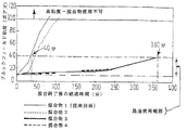
結合混合物の粘度変化は、混合物の抽出物に対して、25℃の温度でブルックフィールド粘度計で測定したものである。図1に、経過時間に対する粘度の増加を測定した時の曲線を示してある。
【0028】
上述したタイプの糸に対する正確な含浸が、100ポアズ未満、かつ最適値が約40ポアズの粘度である結合剤を用いた場合には、図1の曲線からわかるように、混合が行われてから混合物1が最適使用範囲外になるのに要する時間は、大変短い。混合物1は、他の3つの混合物に対する対照として用いられている。混合物1は、その物質自体、公知であり、フェノール樹脂を用いて生成され、他の強塩基性物質を添加していない。
【0029】
図1からわかるように、混合物1の所要時間は40分以内である。これに対して、混合物2の所要時間は、40分以上であり、混合物3及び混合物4では、100分以上である。混合物3及び4の粘度は、360分経過しても、最適範囲、つまり40ポアズ以下に保たれるようになっている。
【0030】
ここには示していないが、追加の試験により、樹脂に対する強塩基性物質の重さの割合に基づいた好ましい範囲は、8〜15%であることが分かった。これにより、結合混合物が9〜10のpH値に到達しうるようになる。
【0031】
いくつかの応用例では、SBRタイプのラテックスよりも熱強度の大きいNBRタイプのラテックスを使用することが好ましい。
【0032】
表2は、さらに2つの混合物5及び混合物6の組成を示している。
【0033】
【表2】
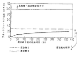
表2に示した混合物の経過時間に対する粘度の反応を、図2に示してある。図2は、図1と同様に、混合が完了した時点、または、混合が完了したと見なされる瞬間を0として、経過時間に対する粘度変化を示すグラフである。この場合、混合物5は、「対照」として用いられ、強塩基性物質を含んでいない。一方、混合物6では、水酸化カリウムを10重量部含んでいる。
【0035】
図2に示す試験は、25℃で行ったものである。図2に示すように、混合物5の粘度が急激に増加するのに対して、混合物6の粘度は、30ポアズにも達せず、7時間以上も最適値の範囲内である。
【0036】
ラテックスを用いるタイプのものに関して、さらに2つの結合混合物7及び8の組成を用いて、NBRタイプのラテックスを用いる利点を、下の表3に示してある。この結合においては、これら2つの結合混合物は、混合物7がSBRラテックスを、混合物8がNBRラテックスをそれぞれ含有する以外は、上記と同一の重量組成で行われる。
【0037】
【表3】
上述の各結合剤は、糸を含浸するために用いられ、これにより、2対のクラッチライニングが形成される。各対のライニングは、クラッチ摩擦板に取り付けられ、連続したクラッチ係合及び解除試験を、一定の間隔で、試験台上で行う。
【0039】
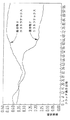
ライニングの温度値、摩擦係数、クラッチの動作回数(各サイクルは、1回の係合動作と1回の解除動作からなる)を測定した。これらの測定値は、図3及び図4に示されている。
【0040】
図4から分かるように、繰り返してクラッチを動作させると、約350℃〜400℃で安定する熱を発生する。また、図3から分かるように、SBRラテックスを含有するライニングの摩擦係数は、かなり減少し、クラッチ動作を約50回行った後では、より急激に減少している。一方、NBRラテックスを含有するライニングの摩擦係数は、概ね一定であり、クラッチ動作を約40回行った後では、増加している。
【0041】
NBRラテックスを含有するライニングでは、クラッチ動作中に、殆んどノイズが発生しない。このノイズは、SBRラテックスを含有するライニングよりも小さい。
【0042】
さらに、本発明によるクラッチライニングの製造方法により、結合剤の組成配合を増やすことができ、選択の幅が広がることにより、種々の適宜な特性を有する摩擦材料を用いて、最終的な製品を製造することができる。これらにより、本発明によるクラッチ摩擦ライニングは、幅広い特性と性能を有することができる。表4は、組成の重要な変更例を示している。表4には、それぞれF1〜F7よりなる7つの例を示している。
【0043】
【表4】
本発明により、溶剤量に対する割合が増加した有効成分を含む結合剤を使用することができる。これは、従来技術の35%またはそれ以下のものと比較して、乾燥抽出物を、結合剤の重量の50%を越える値とすることにより測定することができる。
【0045】
本発明の利点は、第1に、糸の十分な含浸、第2に、含浸後の糸の速乾性である。
【0046】
特に、本発明により、織られたグラスファイバーの少なくとも1本の糸、好ましくは600〜5000テックスの糸で加工された、1〜3本の糸を含む複合糸が、含浸されるようになっている。本発明により生成された結合剤を用いて、一般的に、上述したタイプの糸に、改善された含浸を適用することができる。従って、この含浸された糸から製造されたクラッチライニングは、遠心力に対して、機械的抵抗が増加することになる。
【0047】
適切な比較を行うために、3つのクラッチライニングを製造し、クラッチ摩擦ホイールやクラッチディスクにリベットでそれらを固着するために、貫通孔を設けた。
【0048】
第1のライニングは、従来の材料、つまり、塩素性溶剤の結合剤に含浸された未加工の糸で製造したものである。第2のライニングは、上述の表1及び図1で説明した混合物3に対応する結合剤に含浸された未加工の糸で製造したものである。第3のクラッチ板は、2500テックスで加工された2本の糸からなり、混合物3に対応する結合剤に含浸された複合糸で製造したものである。
【0049】
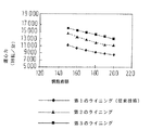
図5は、遠心分離試験の結果を示している。この試験では、変動する値の遠心力に対する試験を行うために、上述の3つのクラッチライニングを、異なる速度で回転した。図5は、閾値、即ち、試験片が熱を帯びて破損する時の毎分回転数で示した回転速度の値を示している。閾値は、慣性直径の関数として表され、以下のように定義される。
【0050】
DI=√1/2 (D2−d2)
D及びdは、それぞれ、ライニングの外径及び内径であり、DIは、慣性直径自体である。
【0051】
【発明の効果】
本発明では、クラッチライニングの遠心強度が十分に改善され、糸が強塩基性水性結合剤と組み合わされた時に、特に高い遠心強度となることが上述の説明から理解されると思う。この配合をNBRラテックスと組み合わすと、上述した全ての利点を得られることが分かった。
【図面の簡単な説明】
【図1】従来の1種類の混合物、及び本発明による方法で用いられる3種類の混合物の水性結合剤の粘度が、どのように時間と共に変化するかを示すグラフである。
【図2】図1と同じ目盛りで、さらに2種類の異なる水性結合剤の混合物の粘度を示すグラフである。
【図3】本発明によるクラッチディスクの性能に関するグラフであり、クラッチの動作回数に対する摩擦係数を示している。
【図4】クラッチの動作回数に対する動作温度を示すグラフである。
【図5】摩擦ライニングの慣性直径に対する遠心分離試験での回転速度を示し、本発明による2つのクラッチライニングを従来のものと比較した時のグラフである。[0001]
BACKGROUND OF THE INVENTION
The present invention relates to a friction material, and more particularly to a friction lining used for a clutch friction wheel designed for dry action, i.e. a friction disk, and a method for producing a friction material for a crowned friction lining. The invention also relates to such a friction lining itself.
[0002]
[Prior art]
Friction linings of the type described above are manufactured in particular with yarns based on inorganic fibers such as glass fibers. Thereby, mechanical strength against centrifugal force generated during operation is given. The base material of the friction lining contains rubber in order to obtain a suitable coefficient of friction and also contains various fillers and binders, in fact phenolic resins, to bind the various components.
[0003]
[Problems to be solved by the invention]
In producing a friction lining, various solvents are usually used, and in particular, for the purpose of dissolving rubber. These solvents are chlorinated solvents. However, since the chlorinated solvent is toxic, the treatment must be performed only on the production line and the generated steam must be recovered. Therefore, there are drawbacks in that it is necessary to prevent contact with workers engaged in manufacturing and outflow of toxic vapors to the environment.
[0004]
It has been proposed to use an aqueous solvent instead of a chlorinated solvent. In this case, it is necessary to use a latex which is a kind of rubber. In fact, the aqueous binder is a mixture of phenolic resin, filler, and latex. This binder is composed of inorganic fibers or other fibers and is used for impregnating the yarn forming the material plate. Thereafter, the blank is heat treated under pressure to form the friction lining itself.
[0005]
Valeo, France, has discovered that the viscosity of aqueous binders increases rapidly in a short time. Therefore, first, the time during which the binder can be used for impregnation is short, and then, the friction characteristics and wear characteristics of the manufactured friction lining vary, which is not preferable.
[0006]
[Means for Solving the Problems]
It is an object of the present invention to provide a method for producing the friction material described above, more specifically, a friction material for a friction lining of a dry friction clutch plate. This friction material is mixed with an aqueous binder that does not have the disadvantages described above.
[0007]
The present invention relates to a method for producing a friction lining of a friction material, particularly a dry friction clutch disk, comprising a process of impregnating a water-based impregnated binder with a yarn mainly composed of inorganic fibers such as glass fiber. , A process comprising a latex together with a phenolic resin containing at least partially phenolate.
[0008]
The phenolate is preferably an alkaline phenolate. Accordingly, it is preferred that a strongly basic component (ie, alkali or other base) is added to the impregnated binder before or after addition of the phenolic resin.
[0009]
The phenol resin is preferably in the form of a powder.
[0010]
The strongly basic component is, for example, potassium or sodium.
[0011]
The ratio of the weight of the strongly basic component to the phenol resin is 6 to 15%, preferably 8 to 15%.
[0012]
According to the present invention, the usable time of the binder can be extended considerably in order to impregnate the yarn and form the framework and blank of the friction lining, and in fact it is about 10 times.
[0013]
In accordance with the present invention, the method of making an impregnated binder includes a premix comprising a filler, a phenolic resin, a strongly basic component, and water, and the following steps of adding latex to the premix.
[0014]
In addition to the advantages described above, the physicochemical properties of the binder are stable throughout the time that the binder is used, so that the quality of the final product, the friction lining itself, is improved and constant. Become.
[0015]
When analyzed in detail, in conventional methods used to date, the addition of powdered phenolic resin to a mixture containing latex drains moisture from the latex. This rapidly increases the viscosity of the binder, making it unsuitable for impregnation.
[0016]
According to the present invention, by using a resin such as phenolate, or by adding a strong base agent that changes at least part of the resin to phenolate, the above-mentioned problems occurring in conventional methods are overcome. Can do.
[0017]
The present invention also relates to a friction lining of a dry friction clutch plate, comprising inorganic fibers such as glass fibers, organic fibers such as polyacrylonitrile fibers or derivatives thereof, resins such as phenolates, fillers, and latexes. A friction lining for a dry friction clutch plate, comprising a yarn containing an aqueous binder containing. This friction lining is preferably formed by the method according to the invention.
[0018]
Other features and advantages of the invention will be apparent from the description of the following examples. Moreover, the product manufactured by the method of this invention is not limited to what is shown in an Example. Next, a description will be given with reference to the drawings.
[0019]
【Example】
The clutch lining, that is, the circular friction lining of a dry friction clutch of an automobile will be described.
[0020]
The aqueous binder is produced by mixing various components. The mixing is preferably carried out in two stages: premixing and final mixing. First, in the preliminary mixing, a phenol resin and a melamine formaldehyde resin, potassium (or sodium or other suitable strong base), and water are mixed. The mixing time is set so that the phenol resin is completely dissolved and the mixture becomes uniform.
[0021]
During final mixing, the latex is added to the premix to produce a uniform final mix.
[0022]
The yarn consists of inorganic fiber yarn such as glass fiber, organic fiber yarn such as polyacrylonitrile fiber and its derivatives, and metal yarn, and metal yarn is up to 75% of the finished clutch lining. It becomes the weight of. The yarn is dried after being pushed into the binder and impregnated.
[0023]
The material plate of the friction lining is formed by placing the impregnated yarn on the protruding portion between the outer diameter and the inner diameter. Subsequently, the blank is heated under pressure. The subsequent heat treatment is preferably performed for product stability.
[0024]
Various mechanical processes such as distortion correction, formation of holes in the raw material plate, and fine powder processing are performed as necessary. The clutch lining thus obtained is designed to be suitable for both sides of the elastic support member in the axial direction of the clutch friction disk or clutch wheel.
[0025]
Four samples of binder were generated as described above. The ratio is shown in Table 1.
[0026]
[Table 1]
The change in viscosity of the combined mixture is measured with a Brookfield viscometer at a temperature of 25 ° C. on the extract of the mixture. FIG. 1 shows a curve when the increase in viscosity with respect to elapsed time is measured.
[0028]
If a correct impregnation for the type of yarn described above is used with a binder having a viscosity of less than 100 poise and an optimum value of about 40 poise, as can be seen from the curve in FIG. The time required for the mixture 1 to go out of the optimum use range is very short. Mixture 1 is used as a control for the other three mixtures. The mixture 1 is known per se, is produced using a phenolic resin, and no other strongly basic substances are added.
[0029]
As can be seen from FIG. 1, the time required for mixture 1 is within 40 minutes. On the other hand, the time required for the mixture 2 is 40 minutes or more, and for the mixture 3 and the
[0030]
Although not shown here, additional tests have shown that the preferred range based on the weight ratio of strongly basic material to resin is 8-15%. This allows the binding mixture to reach a pH value of 9-10.
[0031]
In some applications, it is preferred to use NBR type latex, which has a higher thermal strength than SBR type latex.
[0032]
Table 2 shows the composition of two further mixtures 5 and 6.
[0033]
[Table 2]
The viscosity response to the elapsed time of the mixtures shown in Table 2 is shown in FIG. FIG. 2 is a graph showing a change in viscosity with respect to elapsed time, where 0 is the time when mixing is completed or the moment when mixing is considered to be completed, as in FIG. 1. In this case, mixture 5 is used as a “control” and does not contain strong basic substances. On the other hand, the mixture 6 contains 10 parts by weight of potassium hydroxide.
[0035]
The test shown in FIG. 2 was conducted at 25 ° C. As shown in FIG. 2, the viscosity of the mixture 5 rapidly increases, whereas the viscosity of the mixture 6 does not reach 30 poise and is within the optimum value range for 7 hours or more.
[0036]
The advantages of using NBR type latexes with the composition of two additional
[0037]
[Table 3]
Each of the binders described above is used to impregnate the yarn, thereby forming two pairs of clutch linings. Each pair of linings is attached to a clutch friction plate and a continuous clutch engagement and release test is performed on the test bench at regular intervals.
[0039]
The temperature value of the lining, the coefficient of friction, and the number of clutch operations (each cycle consists of one engagement operation and one release operation) were measured. These measurements are shown in FIGS. 3 and 4.
[0040]
As can be seen from FIG. 4, when the clutch is operated repeatedly, heat that is stable at about 350 ° C. to 400 ° C. is generated. Further, as can be seen from FIG. 3, the friction coefficient of the lining containing the SBR latex is considerably decreased, and is decreased more rapidly after the clutch operation is performed about 50 times. On the other hand, the friction coefficient of the lining containing NBR latex is substantially constant and increases after about 40 clutch operations.
[0041]
In a lining containing NBR latex, little noise is generated during clutch operation. This noise is less than a lining containing SBR latex.
[0042]
Furthermore, the clutch lining manufacturing method according to the present invention can increase the composition of the binder, and the range of choices can be expanded to manufacture a final product using friction materials having various appropriate characteristics. can do. Thus, the clutch friction lining according to the present invention can have a wide range of characteristics and performance. Table 4 shows important variations in composition. Table 4 shows seven examples each composed of F1 to F7.
[0043]
[Table 4]
According to the present invention, a binder containing an active ingredient whose ratio to the amount of solvent is increased can be used. This can be measured by taking the dry extract to a value that exceeds 50% of the weight of the binder, compared to 35% or less of the prior art.
[0045]
The advantages of the present invention are firstly sufficient impregnation of the yarn and secondly quick drying of the yarn after impregnation.
[0046]
In particular, according to the invention, a composite yarn comprising 1 to 3 yarns, processed with at least one yarn of woven glass fiber, preferably 600 to 5000 tex yarn, is impregnated. Yes. With the binder produced according to the invention, improved impregnation can generally be applied to yarns of the type described above. Therefore, the clutch lining manufactured from this impregnated yarn has increased mechanical resistance against centrifugal force.
[0047]
In order to make a proper comparison, three clutch linings were manufactured and through holes were provided to secure them to the clutch friction wheel or clutch disc with rivets.
[0048]
The first lining is made of a conventional material, ie, a raw yarn impregnated with a chlorinated solvent binder. The second lining is made of raw yarn impregnated with a binder corresponding to the mixture 3 described in Table 1 and FIG. 1 above. The third clutch plate is composed of two yarns processed at 2500 tex and is made of a composite yarn impregnated with a binder corresponding to the mixture 3.
[0049]
FIG. 5 shows the results of the centrifugation test. In this test, the three clutch linings described above were rotated at different speeds in order to test for varying values of centrifugal force. FIG. 5 shows the threshold value, that is, the value of the rotational speed indicated by the number of revolutions per minute when the test piece is heated and damaged. The threshold is expressed as a function of the inertia diameter and is defined as follows:
[0050]
DI = √1 / 2 (D 2 −d 2 )
D and d are the outer diameter and inner diameter of the lining, respectively, and DI is the inertia diameter itself.
[0051]
【The invention's effect】
It will be understood from the above description that in the present invention, the centrifugal strength of the clutch lining is sufficiently improved, and particularly high centrifugal strength is obtained when the yarn is combined with a strongly basic aqueous binder. It has been found that when this formulation is combined with NBR latex, all of the advantages described above can be obtained.
[Brief description of the drawings]
FIG. 1 is a graph showing how the viscosity of an aqueous binder of one conventional mixture and three mixtures used in the process according to the invention varies with time.
FIG. 2 is a graph showing the viscosity of a mixture of two different aqueous binders on the same scale as FIG.
FIG. 3 is a graph relating to the performance of a clutch disk according to the present invention, showing the coefficient of friction with respect to the number of clutch operations.
FIG. 4 is a graph showing the operating temperature with respect to the number of clutch operations.
FIG. 5 is a graph showing a rotational speed in a centrifugal separation test with respect to an inertia diameter of a friction lining, and comparing two clutch linings according to the present invention with a conventional one.
Claims (14)
(1)グラスファイバーから成る無機繊維とポリアクリロニトリル繊維またはその誘導体から成る有機繊維;および(1) inorganic fibers composed of glass fibers and organic fibers composed of polyacrylonitrile fibers or derivatives thereof; and
(2)フェノール樹脂、強塩基性成分、充填剤、及びSBR又はNBRタイプのラテックスを含む水性含浸結合剤とを含むことを特徴とする乾式摩擦クラッチ板の摩擦ライニング。(2) A friction lining of a dry friction clutch plate comprising a phenol resin, a strongly basic component, a filler, and an aqueous impregnated binder containing SBR or NBR type latex.
Applications Claiming Priority (2)
| Application Number | Priority Date | Filing Date | Title |
|---|---|---|---|
| FR9807657A FR2779989B1 (en) | 1998-06-17 | 1998-06-17 | METHOD FOR MANUFACTURING A FRICTION MATERIAL AND IN PARTICULAR A FRICTION CROWN FOR A CLUTCH FRICTION DISC AND A CLUTCH CROWN |
| FR9807657 | 1998-06-17 |
Publications (3)
| Publication Number | Publication Date |
|---|---|
| JP2000039033A JP2000039033A (en) | 2000-02-08 |
| JP2000039033A5 JP2000039033A5 (en) | 2006-06-29 |
| JP4664458B2 true JP4664458B2 (en) | 2011-04-06 |
Family
ID=9527513
Family Applications (1)
| Application Number | Title | Priority Date | Filing Date |
|---|---|---|---|
| JP17109899A Expired - Fee Related JP4664458B2 (en) | 1998-06-17 | 1999-06-17 | Lining of dry friction clutch and manufacturing method thereof |
Country Status (8)
| Country | Link |
|---|---|
| US (1) | US6503613B1 (en) |
| EP (1) | EP0965770B2 (en) |
| JP (1) | JP4664458B2 (en) |
| KR (1) | KR100630030B1 (en) |
| BR (1) | BR9902284B1 (en) |
| DE (1) | DE69930179T3 (en) |
| ES (1) | ES2259464T5 (en) |
| FR (1) | FR2779989B1 (en) |
Families Citing this family (15)
| Publication number | Priority date | Publication date | Assignee | Title |
|---|---|---|---|---|
| FR2802999A1 (en) * | 1999-12-28 | 2001-06-29 | Valeo | Making friction lining for vehicle clutch by pressure curing mixture of fibers, binders and fillers and heat treating lining to reduce swelling in use |
| JP5183165B2 (en) | 2006-11-21 | 2013-04-17 | 富士フイルム株式会社 | Method for producing article having birefringence pattern |
| CN101205957B (en) * | 2006-12-20 | 2010-08-11 | 包亦波 | Skeleton material of mechanical brake and clutch friction system |
| US20110123929A1 (en) | 2007-01-23 | 2011-05-26 | Fujifilm Corporation | Oxime compound, photosensitive composition, color filter, production method for the color filter, and liquid crystal display element |
| US20080259268A1 (en) | 2007-04-12 | 2008-10-23 | Fujifilm Corporation | Process of producing substrate for liquid crystal display device |
| JP2009223304A (en) | 2008-02-19 | 2009-10-01 | Fujifilm Corp | Substrate for liquid crystal display device and liquid crystal display device |
| FR2930254B1 (en) * | 2008-04-16 | 2011-10-21 | Valeo Materiaux De Friction Sas | SILICONE RESIN COMPOSITIONS, PROCESSES FOR THEIR PREPARATION AND APPLICATIONS THEREOF. |
| KR20090121240A (en) | 2008-05-21 | 2009-11-25 | 후지필름 가부시키가이샤 | Birefringence Pattern Material and Anti-Forgery Laminated Structure |
| JP2010197921A (en) | 2009-02-27 | 2010-09-09 | Fujifilm Corp | Substrate for liquid crystal display device and liquid crystal display device |
| JP5657243B2 (en) | 2009-09-14 | 2015-01-21 | ユー・ディー・シー アイルランド リミテッド | Color filter and light emitting display element |
| EP3239265B1 (en) * | 2014-12-26 | 2019-07-10 | Zeon Corporation | Latex for friction material, and friction material |
| FR3071891B1 (en) * | 2017-09-29 | 2021-04-23 | Valeo Materiaux De Friction | AQUEOUS IMPREGNATION CEMENT |
| FR3073480B1 (en) * | 2017-11-15 | 2020-11-13 | Psa Automobiles Sa | PROCEDURE FOR CHECKING AN ENGAGING DEVICE OF AN ELECTRIC MACHINE OF A HYBRID VEHICLE |
| WO2019163505A1 (en) | 2018-02-21 | 2019-08-29 | 富士フイルム株式会社 | Curable composition, cured object, color filter, method for producing color filter, solid imaging element, and image display device |
| DE102020123040A1 (en) * | 2020-07-13 | 2022-01-13 | Schaeffler Technologies AG & Co. KG | Process for the production of wet friction paper |
Family Cites Families (11)
| Publication number | Priority date | Publication date | Assignee | Title |
|---|---|---|---|---|
| US3743069A (en) † | 1971-06-24 | 1973-07-03 | Johns Manville | Glass fiber friction element |
| US4130537A (en) * | 1977-02-02 | 1978-12-19 | H. K. Porter Company, Inc. | Asbestos free friction element |
| US4118528A (en) † | 1977-07-28 | 1978-10-03 | Raybestos Manhattan, Inc. | Glass fiber friction facing |
| ZA795801B (en) * | 1978-11-04 | 1980-11-26 | Ferodo Ltd | Friction materials |
| US4320823A (en) * | 1979-06-21 | 1982-03-23 | Raybestos-Manhattan, Inc. | Friction members formed from compositions containing aramid fibers and an aqueous heat-hardenable cement comprising a water soluble phenolic resin and a heat-curable elastomer |
| AU8222682A (en) † | 1981-04-10 | 1982-10-14 | Ferodo Limited | Glass yarn friction linings |
| US4476191A (en) * | 1981-11-16 | 1984-10-09 | Ppg Industries, Inc. | Resorcinol-aldehyde resin composition for an adhesive system to be applied to glass fibers |
| GB8609909D0 (en) * | 1986-04-23 | 1986-05-29 | Borden Uk Ltd | Manufacture of frictional elements |
| GB2203746B (en) * | 1987-04-24 | 1990-08-01 | Westinghouse Electric Corp | Improvements in or relating to water-soluble impregnating resins |
| DE4221001A1 (en) † | 1992-06-26 | 1994-01-05 | Frenzelit Werke Gmbh & Co Kg | Temperature-resistant yarn-plied yarn, consists 60-95 weight per cent of staple fibres - made of drawn mineral fibres with min. fibre dia. of over 3 micrometers |
| JPH0762329A (en) † | 1993-08-24 | 1995-03-07 | Hitachi Chem Co Ltd | Mixture for friction material and friction material made thereof |
-
1998
- 1998-06-17 FR FR9807657A patent/FR2779989B1/en not_active Expired - Lifetime
-
1999
- 1999-06-14 ES ES99111495T patent/ES2259464T5/en not_active Expired - Lifetime
- 1999-06-14 EP EP99111495A patent/EP0965770B2/en not_active Expired - Lifetime
- 1999-06-14 DE DE69930179T patent/DE69930179T3/en not_active Expired - Lifetime
- 1999-06-16 KR KR1019990022566A patent/KR100630030B1/en not_active Expired - Fee Related
- 1999-06-16 BR BRPI9902284-2A patent/BR9902284B1/en not_active IP Right Cessation
- 1999-06-17 JP JP17109899A patent/JP4664458B2/en not_active Expired - Fee Related
- 1999-06-17 US US09/335,025 patent/US6503613B1/en not_active Expired - Lifetime
Also Published As
| Publication number | Publication date |
|---|---|
| KR20000006225A (en) | 2000-01-25 |
| DE69930179T3 (en) | 2010-01-07 |
| ES2259464T5 (en) | 2009-10-09 |
| DE69930179T2 (en) | 2006-11-23 |
| KR100630030B1 (en) | 2006-09-27 |
| EP0965770A1 (en) | 1999-12-22 |
| FR2779989A1 (en) | 1999-12-24 |
| BR9902284B1 (en) | 2009-12-01 |
| EP0965770B2 (en) | 2009-06-17 |
| US6503613B1 (en) | 2003-01-07 |
| ES2259464T3 (en) | 2006-10-01 |
| DE69930179D1 (en) | 2006-05-04 |
| FR2779989B1 (en) | 2000-08-04 |
| JP2000039033A (en) | 2000-02-08 |
| EP0965770B1 (en) | 2006-03-08 |
| BR9902284A (en) | 2000-05-23 |
Similar Documents
| Publication | Publication Date | Title |
|---|---|---|
| JP4664458B2 (en) | Lining of dry friction clutch and manufacturing method thereof | |
| EP0271965A2 (en) | Friction materials and their manufacture | |
| US8222317B2 (en) | Wet friction material | |
| US7294188B2 (en) | Mixing method for friction material with a pre-mix in a single mixer | |
| CN108431328B (en) | Polyester fiber, method for preparing the same, and tire cord comprising the same | |
| US2757109A (en) | Bearing composition, bearing, and method of making same | |
| CA1059277A (en) | Dry mix organic brake linings | |
| US4187133A (en) | Method for manufacturing a clutch facing | |
| JP2002053846A (en) | Method for producing friction material and friction material obtained by the method | |
| JPS6023774B2 (en) | Friction material | |
| WO2016207068A1 (en) | Method for producing a friction material | |
| EP1088176A1 (en) | Method for producing a friction material for a friction gear in a clutch | |
| GB2126594A (en) | Dry friction composition | |
| US1941280A (en) | Friction material and method of making the same | |
| JP3966645B2 (en) | Method for producing wet friction material | |
| FR2532385A1 (en) | DRY FRICTION COMPOSITION, FOR EXAMPLE FOR VEHICLE CLUTCH | |
| JPS6366232A (en) | Wet friction material | |
| JPS5877939A (en) | Wet type friction material | |
| RU2016000C1 (en) | Prepreg for friction materials | |
| RU2265623C1 (en) | Friction material composition | |
| JPS5874775A (en) | Friction material | |
| RU2114877C1 (en) | Composition for impregnation of threads by production of friction clutch strap | |
| JPH0245052B2 (en) | ||
| JPS5978838A (en) | Manufacture of friction material | |
| JPH1163056A (en) | Method for manufacturing wet friction material and wet friction plate |
Legal Events
| Date | Code | Title | Description |
|---|---|---|---|
| A521 | Request for written amendment filed |
Free format text: JAPANESE INTERMEDIATE CODE: A523 Effective date: 20060512 |
|
| A621 | Written request for application examination |
Free format text: JAPANESE INTERMEDIATE CODE: A621 Effective date: 20060512 |
|
| A131 | Notification of reasons for refusal |
Free format text: JAPANESE INTERMEDIATE CODE: A131 Effective date: 20100119 |
|
| A521 | Request for written amendment filed |
Free format text: JAPANESE INTERMEDIATE CODE: A523 Effective date: 20100224 |
|
| TRDD | Decision of grant or rejection written | ||
| A01 | Written decision to grant a patent or to grant a registration (utility model) |
Free format text: JAPANESE INTERMEDIATE CODE: A01 Effective date: 20101214 |
|
| A01 | Written decision to grant a patent or to grant a registration (utility model) |
Free format text: JAPANESE INTERMEDIATE CODE: A01 |
|
| A61 | First payment of annual fees (during grant procedure) |
Free format text: JAPANESE INTERMEDIATE CODE: A61 Effective date: 20110107 |
|
| R150 | Certificate of patent or registration of utility model |
Free format text: JAPANESE INTERMEDIATE CODE: R150 |
|
| FPAY | Renewal fee payment (event date is renewal date of database) |
Free format text: PAYMENT UNTIL: 20140114 Year of fee payment: 3 |
|
| R250 | Receipt of annual fees |
Free format text: JAPANESE INTERMEDIATE CODE: R250 |
|
| LAPS | Cancellation because of no payment of annual fees |