JP4665222B2 - 3D structure analysis method and 3D structure analysis apparatus - Google Patents
3D structure analysis method and 3D structure analysis apparatus Download PDFInfo
- Publication number
- JP4665222B2 JP4665222B2 JP2001241631A JP2001241631A JP4665222B2 JP 4665222 B2 JP4665222 B2 JP 4665222B2 JP 2001241631 A JP2001241631 A JP 2001241631A JP 2001241631 A JP2001241631 A JP 2001241631A JP 4665222 B2 JP4665222 B2 JP 4665222B2
- Authority
- JP
- Japan
- Prior art keywords
- ray
- fluorescent
- layer
- multilayer structure
- theoretical value
- Prior art date
- Legal status (The legal status is an assumption and is not a legal conclusion. Google has not performed a legal analysis and makes no representation as to the accuracy of the status listed.)
- Expired - Fee Related
Links
Images

Landscapes
- Production Of Multi-Layered Print Wiring Board (AREA)
- Analysing Materials By The Use Of Radiation (AREA)
Description
【0001】
【発明の属する技術分野】
本発明は、X線をプローブとして、例えばビルドアップ基板のような多層構造体の3次元構造を非破壊的に分析する手段に関するものである。
【0002】
【従来の技術】
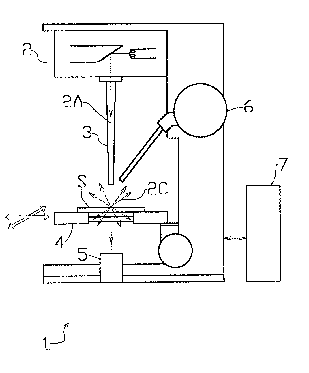
従来より、試料の内部構造を非破壊的に分析する手段として走査型X線顕微鏡が用いられている。図6は、従来の走査型X線顕微鏡の構成を示す模式図であるが、従来の走査型X線顕微鏡1は、X線を発生させるX線管2と、X線管2から発せられたX線2Aを試料S上に導いて照射するX線ガイドチューブ3と、試料Sを載置して2次元方向に走査可能な試料ステージ4と、試料を透過したX線2Bを検出する透過X線検出器5と、試料Sから発せられる蛍光X線2Cを検出する蛍光X線検出器6と、試料ステージ4の走査制御及び透過X線検出器5或いは蛍光X線検出器6の検出値に基づく画像処理を行うコンピュータ7とを備えてなる。
【0003】
前記従来の走査型X線顕微鏡1によれば、試料Sの測定領域をコンピュータ7に入力し、該入力情報に基づいて試料ステージ4の走査が制御されて、試料Sの測定領域にX線2がスキャンされ、測定領域の各スキャン座標における透過X線検出器5或いは蛍光X線検出器6の検出値に基づいて測定領域の2次元画像が作成されてディスプレイ等(図示せず)に表示される。
【0004】
【発明が解決しようとする課題】
しかし、従来の走査型X線顕微鏡1では、試料Sの2次元構造は分析できるが3次元構造を分析することは難しい。例えば、プラスチック等の絶縁層を介在させて銅層からなる回路が積層されたビルドアップ基板の場合であれば、透過X線検出値又は蛍光X線検出値は銅層の厚さに比例するので、銅層1層当りの厚みが既知であれば銅層の数を算出することができるが、多層構造の中のどの層位置に銅層が存在するのかを特定することは困難である。
【0005】
本発明は、かかる課題を解決すべくなされたものであり、多層構造体の3次元構造分析において、X線をプローブとして多層構造体の3次元情報を高精度、簡便且つ迅速に得ることができる手段を提供することを目的とする。
【0006】
【課題を解決するための手段】
前記目的を達成するためになされた本発明の請求項1に係る多層構造体の3次元構造分析方法は、多層構造体の表面にX線を照射して、透過X線及び蛍光X線を検出し、該検出値に基づいて多層構造体の3次元構造を分析する方法であって、入力情報に基づいて多層構造体の被検出層の層数に対する透過X線理論値、及び被検出層の層位置に対する反射蛍光X線理論値並びに透過蛍光X線理論値を算出して、各層数に対する透過X線理論値、及び各層位置に対する反射蛍光X線理論値並びに透過蛍光X線理論値を表した理論値テーブルを作成するステップと、多層構造体の表面にX線を2軸方向にスキャンさせながら照射するステップと、各スキャン座標において透過X線を検出するステップと、各スキャン座標において多層構造体の反射側に発生する反射蛍光X線を検出するステップと、各スキャン座標において多層構造体の透過側に発生する透過蛍光X線を検出するステップと、前記理論値テーブルと、透過X線検出値、反射蛍光X線検出値、及び透過蛍光X線検出値とに基づいて各スキャン座標毎の多層構造体の被検出層の層位置を解析するステップと、各スキャン座標毎に多層構造体の被検出層の層位置をマッピングして、多層構造体の3次元構造を示す画像を作成するステップとを含むものである。
【0007】
また、本発明(請求項2)は、請求項1に記載の3次元構造分析方法において、各スキャン座標毎の多層構造体の被検出層の層位置の解析は、透過X線理論値と透過X線検出値とに基づいて被検出層の層数を決定した後、反射蛍光X線理論値及び透過蛍光X線理論値と、反射蛍光X線検出値及び透過蛍光X線検出値とに基づいて、被検出層の層位置を決定するものである。
【0008】
また、本発明の請求項3に係る多層構造体の3次元構造分析装置は、X線源と、X線源から発生したX線を多層構造体上に集光して照射するX線集光素子と、多層構造体の表面に対してX線を2軸方向にスキャンさせるスキャン機構と、多層構造体を透過した透過X線を検出する透過X線検出器と、多層構造体の反射側に発生した反射蛍光X線を検出する反射側蛍光X線検出器と、多層構造体の透過側に発生した透過蛍光X線を検出する透過側蛍光X線検出器と、入力情報に基づいて多層構造体の被検出層の層数に対する透過X線理論値、及び被検出層の層位置に対する反射蛍光X線理論値並びに透過蛍光X線理論値を算出して、各層数に対する透過X線理論値、及び各層位置に対する反射蛍光X線理論値並びに透過蛍光X線理論値を表した理論値テーブルを作成し、該理論値テーブルと、透過X線検出値、反射蛍光X線検出値、及び透過蛍光X線検出値とに基づいて、各スキャン座標毎に多層構造体の被検出層の層位置を解析して多層構造体の3次元構造を画像化する制御演算部とを具備してなるものである。
【0009】
また、本発明(請求項4)は、請求項3に記載の3次元構造分析装置において、前記制御演算部による各スキャン座標毎の多層構造体の被検出層の層位置の解析は、透過X線理論値と透過X線検出値とに基づいて被検出層の層数を決定した後、反射蛍光X線理論値及び透過蛍光X線理論値と、反射蛍光X線検出値及び透過蛍光X線検出値とに基づいて、被検出層の層位置を決定するものである。
【0010】
また、本発明の請求項5に係る多層構造解析プログラムは、多層構造体の表面にX線をスキャンさせながら照射することにより得られた透過X線検出値及び蛍光X線検出値に基づいて多層構造体の3次元構造を解析するためのプログラムであって、入力情報に基づいて多層構造体の被検出層の層数に対する透過X線理論値、及び被検出層の層位置に対する反射蛍光X線理論値並びに透過蛍光X線理論値を算出して、各層数に対する透過X線理論値、及び各層位置に対する反射蛍光X線理論値並びに透過蛍光X線理論値を表した理論値テーブルを作成する手順と、前記理論値テーブルと、各スキャン座標において検出された透過X線検出値、多層構造体の反射側で検出された反射蛍光X線検出値、及び多層構造体の透過側で検出された透過蛍光X線検出値とに基づいて各スキャン座標毎の多層構造体の被検出層の層位置を解析する手順と、各スキャン座標毎に多層構造体の被検出層の層位置をマッピングして、多層構造体の3次元構造を示す画像を作成する手順とをコンピュータに実行させるものである。
【0011】
また、本発明(請求項6)は、請求項5に記載の多層構造解析プログラムにおいて、各スキャン座標毎の多層構造体の被検出層の層位置の解析は、透過X線理論値と透過X線検出値とに基づいて被検出層の層数を決定した後、反射蛍光X線理論値及び透過蛍光X線理論値と、反射蛍光X線検出値及び透過蛍光X線検出値とに基づいて、被検出層の層位置を決定するものである。
【0012】
【発明の実施の形態】
以下、本発明の実施の形態に係る多層構造体の3次元構造分析装置について、図面を用いて具体的に説明する。
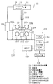
図1に示すように、本3次元構造分析装置100は、X線源101と、X線源101から発生したX線10を試料S上に集光するX線集光素子102と、X線スキャン機構103と、試料となる多層構造体を載置するための試料ステージ104と、透過X線を検出する透過X線検出器105と、反射側に発生する蛍光X線を検出する反射側蛍光X線検出器106と、透過側に発生する蛍光X線を検出する透過側蛍光X線検出器107と、X線スキャン機構103を制御するとともに、透過X線検出器105、反射側蛍光X線検出器106、及び透過側蛍光X線検出器107の検出値に基づいて多層構造体の3次元情報を求め、画像処理を行う制御演算部108とを具備してなるものである。
【0013】
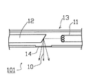
X線源101は、図2に示すように、フィラメント11から出射した電子流がロジウム(Rh)のターゲット12に衝突してX線を発生させるX線管13を備え、該X線管13には図示しない高電圧電源から電気が供給される構造となっている。X線管13内で発生したX線10はベリリウム窓14を透過してX線集光素子102の入射口に入射する。なお、ターゲット12としてはロジウムに代えて、その他の周知のターゲット元素を用いることができる。
【0014】
X線集光素子102は、入射口から入射したX線10を所定の大きさに絞りこみ、輝度の高い細束ビームとするものであり、例えば図3に示すように、先端側に向かって縮径された概略円錐状のケーシング20に、中空のガラス細管からなるX線ガイドチューブ21が複数本内挿された所謂ポリキャピラリを用いることができる。X線ガイドチューブ21も先端側に向かって縮径されており、図に示すように、X線ガイドチューブ21に入射されたX線10は、X線ガイドチューブ21の内壁で全反射しながら所定の大きさに絞られて出射する。これにより、X線源101から放射状に発生したX線10の一部が入射口21aへ入射し、複数のX線ガイドチューブ21内で全反射を繰り返しながら所定の大きさに絞られて出射口21bから細束ビームとなって、例えばスポット径が約30μmのスポットで試料Sに照射される。なお、X線集光素子102をポリキャピラリに代えて、X線源101からのX線を輝度の高い細束ビームに集光するその他の集光素子、例えばモノキャピラリからなるものとすることもできる。
【0015】
X線スキャン機構103は、前記X線源101とX線集光素子102とを図1における図面表裏方向に走査し、各走査毎に試料ステージ104を図面左右方向のいずれかに1段スライド移動して、試料Sの表面にX線10をスキャンさせるものであり、例えば、モータとボールネジとを具備してなる周知のスライド機構である。なお、X線のスキャン方法はこれに限定されるものではなく、例えば、X線源101及びX線集光素子102を固定して試料ステージ104を2軸方向に動作させる等、その他のスキャン方法を採用することができる。
【0016】
透過X線検出器105は、試料ステージ104の下方に配設されて、試料Sを透過した透過X線11を検出するものであり、一方、反射側蛍光X線検出器106は、試料ステージ104の上方の2箇所に配設されて、試料Sから反射側に発生する反射蛍光X線12rを検出し、透過側蛍光X線検出器107は、試料ステージ104の下方の2箇所に配設されて、試料Sから透過側に発生する透過蛍光X線12tを検出するものである。これら透過X線検出器及び蛍光X線検出器には、例えば比例計数管やシンチレータ等、周知のX線検出手段を用いることができる。
【0017】
制御演算部108は、CPU80と、メモリ81と、ディスプレイ等の表示部82と、キーボード又はマウス等の入力手段83とを具備してなるものであり、例えば、更にROMやハードディスク等を有するコンピュータに多層構造解析プログラムがインストールされたものである。該制御演算部108は、適当なインターフェースを介して、X線スキャン機構103、透過X線検出器105、反射側蛍光X線検出器106、及び透過側蛍光X線検出器107と接続されて、X線スキャン機構103と双方向通信でき、且つ、透過X線検出器105、反射側蛍光X線検出器106、及び透過側蛍光X線検出器107から出力される検出値を受信できるものとなっている。なお、制御演算部108をコンピュータに代えて、各機能毎の専用ハードウェア等で実現することもできることは勿論である。
【0018】
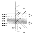
次に、本発明に係る多層構造体の3次元構造分析方法の原理について、図4に示すビルドアップ基板の断面構造を一例に説明する。
図4は、プラスチック層を夫々介在させて6層の銅(Cu)層が積層されたビルドアップ基板の一部の断面構造を示したものであり、該断面において、銅層は第2層め、第3層め、及び第5層めに存在する。ここに、図に示すように、ビルドアップ基板の垂直方向からX線集光素子102により集光されたX線10が照射されると、該X線10は該ビルドアップ基板を透過して透過X線11が透過側に発生するとともに、各銅層において反射側及び透過側へ反射蛍光X線12r又は透過蛍光X線12tが発生する。該透過X線11は透過X線検出器105により、反射蛍光X線12rは反射側蛍光X線検出器106により、透過蛍光X線12tは透過側蛍光X線検出器107により夫々検出される。
【0019】
一方、試料となるビルドアップ基板の情報から、各層に銅層が存在する場合の理論値を予め求めておく。即ち、透過X線11については、銅層の数が0から6までの透過X線理論値Itを求め、蛍光X線12r、12tについては、銅層の数が1で第1層から第6層夫々に銅層が存在する6つの場合と、銅層の数が2で第1層と第2層、第1層と第3層、第1層と第4層、・・・のように各々15の各層の組合せと、銅層の数が3で同様に各々20の各層の組合せと、銅層の数が4で同様に各々15の各層の組合せと、及び銅層の数が5について6つの場合と、の計62種類の層位置について反射蛍光X線理論値Ifr及び透過蛍光X線理論値Iftを夫々求める。なお、銅層の数が0又は6の場合は銅層の位置を特定するまでもないので、その場合の反射蛍光X線理論値Ifr及び透過蛍光X線理論値Iftは算出しなくてもよい。
【0020】
以下、図4に示したビルドアップ基板のように、銅層が6層中3層であって第2層め、第3層め、及び第5層めに位置する場合を例に、前記理論値の算出について詳細に説明する。
【0021】
銅層が3層である場合の透過X線理論値Itは、入射X線強度、銅層の厚さ並びにロジウムKα線に対する線吸収係数、及びプラスチック層の厚さ並びにロジウムKα線に対する線吸収係数から次の式により求められる。
【数1】
一方、第2層め、第3層め、及び第5層めの各銅層から反射側に発生する反射蛍光X線理論値Ifr、及び透過側に発生する透過蛍光X線理論値Iftは、銅層の厚さ、ロジウムKα線に対する線吸収係数、並びに銅Kα線に対する線吸収係数、プラスチック層の厚さ、ロジウムKα線に対する線吸収係数、並びに銅Kα線に対する線吸収係数、銅の蛍光X線発生効率、及び蛍光X線の取出し角から次の式により求められる。
【数2】
このようにして、銅層が6層中3層であって第2層め、第3層め、及び第5層めに位置する場合の透過X線理論値It、反射蛍光X線理論値Ifr、及び透過蛍光X線理論値Iftが求められる。
更に、前記式(1)、式(2)、及び式(3)と同様にして、各層に銅層が存在するすべての場合について予め透過X線理論値It、反射蛍光X線理論値Ifr、及び透過蛍光X線理論値Iftを求め、銅層の層数と透過X線理論値It、層位置と反射蛍光X線理論値Ifr及び透過蛍光X線理論値Iftとを対応させた理論値テーブルを作成する。
【0024】
得られた前記理論値テーブルに基づいて、透過X線検出器105、反射側蛍光X線検出器106、及び透過側蛍光X線検出器107により夫々検出された透過X線11、反射蛍光X線12r、及び透過蛍光X線12tの各検出値と最もよく合致する各理論値を判別して、銅層の層数及び層位置を解析する。
【0025】
ここで、蛍光X線12r又は蛍光X線12tの各検出値のいずれか一方のみを用いて銅層の層位置を解析した場合、例えば、反射蛍光X線12rの検出値のみから層位置を解析するとすれば、入射X線の強度や検出器の感度等により、例えば、第3層めと第4層めに銅層がある場合の反射蛍光X線理論値Ifrと、第3層めと第5層めに銅層がある場合の反射蛍光X線理論値Ifrとの差が非常に小さくなることもある。更に、検出値にはある程度の検出誤差が生ずることを考慮すると、各反射蛍光X線理論値Ifrの差が小さくなれば反射蛍光X線12rの検出値と合致する反射蛍光X線理論値Ifrを判別することが困難となる。本発明では、かかる判別不能を回避すべく、反射蛍光X線12r及び透過X線12tの双方を検出し、反射蛍光X線理論値Ifr及び透過蛍光X線理論値Iftと比較して銅層の位置を解析するようにしているので、検出誤差等を考慮しても精度よく層位置を求めることができる。
【0026】
なお、反射蛍光X線12rと透過蛍光X線12tの検出値は、双方の差や比を求めて解析してもよく、また、いずれか一方の蛍光X線のみでは各理論値の差が判別可能な値より小さくなる場合にのみ、双方の蛍光X線の理論値及び検出値を用いるような判別方法を採ることもできる。
【0027】
また、積層数が多い多層構造体の場合には理論値テーブルのデータ量が大きく、各検出値との比較、判別が煩雑となり得るので、まず、透過X線理論値Itと透過X線11の検出値とから被検出層の層数を決定し、決定された層数において各層位置の反射蛍光X線理論値Ifr及び透過蛍光X線理論値Iftと、反射蛍光X線12r及び透過蛍光X線12tの検出値とから被検出層の層位置を決定すれば、被検出層の層位置の決定速度が向上される。例えば、図4に示すビルドアップ基板であれば、まず、透過X線11の検出値から銅層の数が3であることが決定され、層数が3である場合の層位置の20の組合せについてのみ反射蛍光X線12r及び透過蛍光X線12tの検出値を比較して、第2層め、第3層め、及び第5層めに銅層があることが決定される。
【0028】
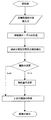
以下、前記3次元構造分析装置100の動作について、図5を参照しながら説明する。
まず前処理として、試料ステージ104に、例えばビルドアップ基板等の多層構造体を固定してプレスキャンを行うことにより、表示部82に多層構造体表面の概略画像が表示され、該概略画像の所望範囲を入力手段83で指定することにより、多層構造体の測定領域が制御演算部108に入力される(S1)。
【0029】
次に、多層構造体の情報、例えば前述したような、プラスチック層を介在させて銅層を積層したビルドアップ基板であれば、銅層の数、銅層及びプラスチック層の厚さ等を入力する(S2)。入射X線の強度は、例えば検出器を設けて入射X線強度を検出し、該検出値を制御演算部108に出力して利用することができ、また、蛍光X線の取出し角等は装置固有の値であるので、分析毎に入力せずに、例えば制御演算部108に固有データとして格納して利用することもできる。また、被検出層等の各線吸収係数や蛍光X線発生効率も分析毎に入力せずに、例えば分析対象とされるであろう元素等を予め想定して選択データとして制御演算部108に格納しておき、分析時に入力手段83で被検出層の元素名等を入力することにより選択データから各線吸収係数等を抽出して利用することもできる。
前記多層構造体情報に基づいて、制御演算部108は、各透過X線理論値It、反射蛍光X線理論値Ifr、及び透過蛍光X線理論値Iftを夫々算出して、理論値テーブルを作成しメモリ81に格納する(S3)。
【0030】
次に、制御演算部108は、スキャン機構103を動作させて、X線源101から発生されたX線10を試料Sの測定領域にスキャンさせながら照射し、これにより発生した透過X線11、反射蛍光X線12r、及び透過蛍光X線12tを、各々透過X線検出器105、反射側X線検出器106、又は透過側X線検出器107で夫々検出する(S4)。
【0031】
得られた検出値は制御演算部108に出力され、制御演算部108は、該検出値と前記理論値テーブルとを比較して、各スキャン座標について銅層の層数及び層位置を決定して3次元情報として記憶する。詳細には、透過X線11の検出値から理論値テーブルに基づいて銅層の層数を決定する(S5)。層数が0又は6であれば一義的に層位置を決定し、そのスキャン座標における3次元情報として記憶する(S6)。層数が2から5のいずれかであれば、反射蛍光X線12r及び透過蛍光X線12tの検出値を理論値テーブルのうち該層数に対応する各反射蛍光X線理論値Ifr及び各透過蛍光X線理論値Iftと比較して層位置を決定し(S7)、そのスキャン座標における3次元情報として記憶する(S6)。測定領域全域についてスキャンが終了し、各スキャン座標の3次元情報が得られれば、制御演算部108は、該3次元情報をマッピングして各銅層の2次元画像を作成し、表示部82に表示する(S8)。これにより、ビルドアップ基板等の多層構造体の各層毎の構造解析を行うことができる。
【0032】
なお、本実施の形態では、銅からなる被検出層が6層積層されたビルドアップ基板を例に説明したが、積層数や被検出層の元素等が異なる多層構造体についても本発明に係る3次元構造分析方法及び3次元構造分析装置が利用できることは勿論である。
また、本実施の形態では、得られた3次元情報から多層構造体の各層毎の2次元画像を作成するものとしているが、これに代えて又は更に、多層構造体の断面画像や立体画像をも作成できる。
【0033】
【発明の効果】
以上説明したように、本発明によれば、多層構造体の情報に基づいて予め透過X線理論値、反射蛍光X線理論値、及び透過蛍光X線理論値を算出し、該多層構造体にX線をスキャンしながら照射することにより得られた透過X線、反射蛍光X線、及び透過蛍光X線各々の検出値と、前記各理論値とを比較して前記多層構造体における被検出層の数及び位置を判別して3次元情報を得るようにしたので、多層構造体の3次元構造を分析して該3次元構造を示す画像を高精度且つ簡便に得ることができる。
【0034】
また、本発明によれば、各スキャン座標毎の多層構造体の被検出層の層位置の解析を、透過X線理論値と透過X線検出値とに基づいて被検出層の層数を決定した後、反射蛍光X線理論値及び透過蛍光X線理論値と、反射蛍光X線検出値及び透過蛍光X線検出値とに基づいて、被検出層の層位置を決定するようにしたので、各反射蛍光X線理論値及び各透過蛍光X線理論値と、各反射蛍光X線検出値及び各透過蛍光X線検出値とを比較する処理ステップ数が少なくなり、多層構造体の層位置の決定速度を向上させることが可能となる。
【図面の簡単な説明】
【図1】本発明の実施の形態に係る多層構造体の3次元構造分析装置100の構成を示す模式図である。
【図2】X線源101の構成を示す模式図である。
【図3】X線集光素子102の構成を示す模式図である。
【図4】多層構造体の3次元構造分析原理を説明するための模式図である。
【図5】3次元構造分析装置100の動作を説明するためのフローチャートである。
【図6】従来の走査型X線顕微鏡1の構成を示す模式図である。
【符号の説明】
100 3次元構造分析装置
101 X線源
102 X線集光素子
103 スキャン機構
104 試料ステージ
105 透過X線検出器
106 反射側蛍光X線検出器
107 透過側蛍光X線検出器
108 制御演算部[0001]
BACKGROUND OF THE INVENTION
The present invention relates to a means for nondestructively analyzing a three-dimensional structure of a multilayer structure such as a build-up substrate using an X-ray as a probe.
[0002]
[Prior art]
Conventionally, a scanning X-ray microscope has been used as a means for nondestructively analyzing the internal structure of a sample. FIG. 6 is a schematic diagram showing the configuration of a conventional scanning X-ray microscope. The conventional
[0003]
According to the conventional
[0004]
[Problems to be solved by the invention]
However, although the conventional
[0005]
The present invention has been made to solve such a problem, and in a three-dimensional structure analysis of a multilayer structure, it is possible to obtain three-dimensional information of the multilayer structure with high accuracy, simply and quickly using an X-ray as a probe. It aims to provide a means.
[0006]
[Means for Solving the Problems]
In order to achieve the above object, a method for analyzing a three-dimensional structure of a multilayer structure according to
[0007]
Further, according to the present invention (Claim 2), in the three-dimensional structure analysis method according to
[0008]
According to a third aspect of the present invention, there is provided a three-dimensional structural analysis apparatus for a multilayer structure, which collects and irradiates an X-ray source and X-rays generated from the X-ray source on the multilayer structure. An element, a scanning mechanism for scanning X-rays biaxially with respect to the surface of the multilayer structure, a transmission X-ray detector for detecting transmitted X-rays transmitted through the multilayer structure, and a reflection side of the multilayer structure A reflection-side fluorescent X-ray detector that detects the generated reflected fluorescent X-ray, a transmission-side fluorescent X-ray detector that detects the transmitted fluorescent X-ray generated on the transmission side of the multilayer structure, and a multilayer structure based on input information Calculate the theoretical value of transmitted X-ray with respect to the number of layers to be detected in the body, the theoretical value of reflected fluorescent X-ray with respect to the layer position of the detected layer, and the theoretical value of transmitted fluorescent X-ray; The reflected fluorescent X-ray theoretical value and the transmitted fluorescent X-ray theoretical value for each layer position are shown. Create a logical value table, and based on the theoretical value table, the transmitted X-ray detection value, the reflected fluorescent X-ray detection value, and the transmitted fluorescent X-ray detection value, the detected layer of the multilayer structure for each scan coordinate And a control operation unit that analyzes the layer position of the multi-layer structure and images the three-dimensional structure of the multilayer structure.
[0009]
Further, according to the present invention (Claim 4), in the three-dimensional structure analysis apparatus according to Claim 3, the analysis of the layer position of the detection layer of the multilayer structure for each scan coordinate by the control calculation unit is performed by transmission X After determining the number of layers to be detected based on the theoretical X-ray value and the detected transmitted X-ray value, the reflected fluorescent X-ray theoretical value, the transmitted fluorescent X-ray theoretical value, the reflected fluorescent X-ray detected value, and the transmitted fluorescent X-ray Based on the detection value, the layer position of the layer to be detected is determined.
[0010]
The multilayer structure analysis program according to
[0011]
According to the present invention (Claim 6), in the multilayer structure analysis program according to
[0012]
DETAILED DESCRIPTION OF THE INVENTION
Hereinafter, a multilayer structure three-dimensional structure analysis apparatus according to an embodiment of the present invention will be specifically described with reference to the drawings.
As shown in FIG. 1, the three-dimensional
[0013]
As shown in FIG. 2, the
[0014]
The
[0015]
The
[0016]
The
[0017]
The
[0018]
Next, the principle of the method for analyzing a three-dimensional structure of a multilayer structure according to the present invention will be described using the cross-sectional structure of the build-up substrate shown in FIG. 4 as an example.
FIG. 4 shows a cross-sectional structure of a part of a build-up substrate in which six copper (Cu) layers are laminated with plastic layers interposed therebetween, in which the copper layer is the second layer. , 3rd layer, and 5th layer. As shown in the figure, when the
[0019]
On the other hand, a theoretical value in the case where a copper layer exists in each layer is obtained in advance from information on a build-up substrate as a sample. That is, for the
[0020]
Hereinafter, as in the build-up board shown in FIG. 4, the above-described theory is based on an example in which the copper layer is 3 out of 6 layers and is located in the second layer, the third layer, and the fifth layer. The calculation of the value will be described in detail.
[0021]
Transmission X-ray theoretical I t when the copper layer is a three-layer, the incident X-ray intensity, the linear absorption coefficient for thickness and rhodium Kα line of copper layer, and the linear absorption to thickness and rhodium Kα ray of the plastic layer It is obtained from the coefficient by the following formula.
[Expression 1]
On the other hand, the reflected fluorescent X-ray theoretical value I fr generated on the reflection side from the second, third, and fifth copper layers, and the transmitted fluorescent X-ray theoretical value I ft generated on the transmission side. Is the thickness of the copper layer, the linear absorption coefficient for rhodium Kα radiation, and the linear absorption coefficient for copper Kα radiation, the thickness of the plastic layer, the linear absorption coefficient for rhodium Kα radiation, and the linear absorption coefficient for copper Kα radiation, It is calculated | required by the following formula from the fluorescent X-ray generation efficiency and the taking-out angle of fluorescent X-rays.
[Expression 2]
Thus, the transmission X-ray theoretical value I t and the reflected fluorescent X-ray theoretical value in the case where the copper layer is 3 out of 6 layers and is located in the second layer, the third layer, and the fifth layer. I fr and the transmitted fluorescent X-ray theoretical value I ft are obtained.
Further, in the same manner as in the above formulas (1), (2), and (3), the transmission X-ray theoretical value I t and the reflected fluorescent X-ray theoretical value I are preliminarily determined in all cases where a copper layer is present in each layer. fr and the transmitted fluorescent X-ray theoretical value I ft are obtained, and the number of copper layers, the transmitted X-ray theoretical value I t , the layer position, the reflected fluorescent X-ray theoretical value I fr and the transmitted fluorescent X-ray theoretical value I ft are determined. Create a corresponding theoretical value table.
[0024]
Based on the obtained theoretical value table, the
[0025]
Here, when the layer position of the copper layer is analyzed using only one of the detected values of the
[0026]
The detected values of the reflected
[0027]
Moreover, large amount of data of the theoretical value table when the number of layers is large multilayer structure, compared with the detection values, the determination can be a complicated, firstly, the transmitted X-ray theory I t transmitted
[0028]
Hereinafter, the operation of the three-dimensional
First, as a pre-processing, a schematic image of the surface of the multilayer structure is displayed on the
[0029]
Next, information on the multilayer structure, such as the number of copper layers, the thicknesses of the copper layers and the plastic layers, etc. are input if the build-up board has a copper layer laminated with a plastic layer as described above. (S2). The intensity of incident X-rays can be used by, for example, providing a detector to detect the incident X-ray intensity and outputting the detected value to the
Based on the multilayer structure information, the
[0030]
Next, the
[0031]
The obtained detection value is output to the
[0032]
In this embodiment, a build-up substrate in which six layers of copper to be detected are stacked has been described as an example. However, a multilayer structure in which the number of layers and the elements of the layer to be detected are different also relates to the present invention. Of course, a three-dimensional structure analysis method and a three-dimensional structure analysis apparatus can be used.
In the present embodiment, a two-dimensional image for each layer of the multilayer structure is created from the obtained three-dimensional information. Instead of or in addition to this, a cross-sectional image or a three-dimensional image of the multilayer structure is used. Can also be created.
[0033]
【The invention's effect】
As described above, according to the present invention, the transmission X-ray theoretical value, the reflected fluorescent X-ray theoretical value, and the transmitted fluorescent X-ray theoretical value are calculated in advance based on the information of the multilayer structure, and the multilayer structure is stored in the multilayer structure. The detected layer of each of the transmitted X-rays, reflected fluorescent X-rays, and transmitted fluorescent X-rays obtained by irradiating while scanning X-rays is compared with the respective theoretical values to be detected in the multilayer structure. Since the three-dimensional information is obtained by discriminating the number and position of the images, it is possible to analyze the three-dimensional structure of the multilayer structure and obtain an image showing the three-dimensional structure with high accuracy and simplicity.
[0034]
According to the present invention, the layer position of the detection layer of the multilayer structure for each scan coordinate is analyzed, and the number of detection layers is determined based on the transmission X-ray theoretical value and the transmission X-ray detection value. After that, since the layer position of the layer to be detected is determined based on the reflected fluorescent X-ray theoretical value and the transmitted fluorescent X-ray theoretical value, and the reflected fluorescent X-ray detected value and the transmitted fluorescent X-ray detected value, The number of processing steps for comparing each reflected fluorescent X-ray theoretical value and each transmitted fluorescent X-ray theoretical value with each reflected fluorescent X-ray detected value and each transmitted fluorescent X-ray detected value is reduced, and the layer position of the multilayer structure is reduced. The determination speed can be improved.
[Brief description of the drawings]
FIG. 1 is a schematic diagram showing a configuration of a multilayer structure three-dimensional
FIG. 2 is a schematic diagram showing a configuration of an
3 is a schematic diagram showing a configuration of an
FIG. 4 is a schematic diagram for explaining the principle of three-dimensional structure analysis of a multilayer structure.
FIG. 5 is a flowchart for explaining the operation of the three-dimensional
FIG. 6 is a schematic diagram showing a configuration of a conventional
[Explanation of symbols]
DESCRIPTION OF
Claims (6)
入力情報に基づいて多層構造体の被検出層の層数に対する透過X線理論値、及び被検出層の層位置に対する反射蛍光X線理論値並びに透過蛍光X線理論値を算出して、各層数に対する透過X線理論値、及び各層位置に対する反射蛍光X線理論値並びに透過蛍光X線理論値を表した理論値テーブルを作成するステップと、
多層構造体の表面にX線を2軸方向にスキャンさせながら照射するステップと、
各スキャン座標において透過X線を検出するステップと、
各スキャン座標において多層構造体の反射側に発生する反射蛍光X線を検出するステップと、
各スキャン座標において多層構造体の透過側に発生する透過蛍光X線を検出するステップと、
前記理論値テーブルと、透過X線検出値、反射蛍光X線検出値、及び透過蛍光X線検出値とに基づいて各スキャン座標毎の多層構造体の被検出層の層位置を解析するステップと、
各スキャン座標毎に多層構造体の被検出層の層位置をマッピングして、多層構造体の3次元構造を示す画像を作成するステップとを含むことを特徴とする3次元構造分析方法。A method of irradiating the surface of a multilayer structure with X-rays, detecting transmitted X-rays and fluorescent X-rays, and analyzing the three-dimensional structure of the multilayer structure based on the detected values,
Based on the input information, the transmission X-ray theoretical value with respect to the number of layers to be detected of the multilayer structure, the reflected fluorescent X-ray theoretical value with respect to the layer position of the detection layer, and the transmission fluorescent X-ray theoretical value are calculated, Creating a theoretical value table representing the theoretical values of transmitted X-rays for X, and the reflected fluorescent X-ray theoretical values and the transmitted fluorescent X-ray theoretical values for each layer position;
Irradiating the surface of the multilayer structure while scanning X-rays in two axial directions;
Detecting transmitted X-rays at each scan coordinate;
Detecting reflected fluorescent X-rays generated on the reflection side of the multilayer structure at each scan coordinate;
Detecting transmitted fluorescent X-rays generated on the transmission side of the multilayer structure at each scan coordinate;
Analyzing the layer position of the detection target layer of the multilayer structure for each scan coordinate based on the theoretical value table, the transmission X-ray detection value, the reflected fluorescent X-ray detection value, and the transmission fluorescent X-ray detection value; ,
Mapping the layer position of the detection layer of the multilayer structure for each scan coordinate, and creating an image showing the three-dimensional structure of the multilayer structure.
X線源から発生したX線を多層構造体上に集光して照射するX線集光素子と、
多層構造体の表面に対してX線を2軸方向にスキャンさせるスキャン機構と、
多層構造体を透過した透過X線を検出する透過X線検出器と、
多層構造体の反射側に発生した反射蛍光X線を検出する反射側蛍光X線検出器と、
多層構造体の透過側に発生した透過蛍光X線を検出する透過側蛍光X線検出器と、
入力情報に基づいて多層構造体の被検出層の層数に対する透過X線理論値、及び被検出層の層位置に対する反射蛍光X線理論値並びに透過蛍光X線理論値を算出して、各層数に対する透過X線理論値、及び各層位置に対する反射蛍光X線理論値並びに透過蛍光X線理論値を表した理論値テーブルを作成し、該理論値テーブルと、透過X線検出値、反射蛍光X線検出値、及び透過蛍光X線検出値とに基づいて、各スキャン座標毎に多層構造体の被検出層の層位置を解析して多層構造体の3次元構造を画像化する制御演算部とを具備してなるものであることを特徴とする3次元構造分析装置。An X-ray source;
An X-ray condensing element that condenses and irradiates X-rays generated from an X-ray source on a multilayer structure;
A scanning mechanism for scanning the surface of the multilayer structure with X-rays in two axial directions;
A transmission X-ray detector for detecting transmission X-rays transmitted through the multilayer structure;
A reflection-side fluorescent X-ray detector for detecting reflected fluorescent X-rays generated on the reflection side of the multilayer structure;
A transmission-side fluorescent X-ray detector that detects transmission fluorescent X-rays generated on the transmission side of the multilayer structure;
Based on the input information, the transmission X-ray theoretical value with respect to the number of layers to be detected of the multilayer structure, the reflected fluorescent X-ray theoretical value with respect to the layer position of the detection layer, and the transmission fluorescent X-ray theoretical value are calculated, A theoretical value table representing the theoretical value of transmitted X-ray, the theoretical value of reflected fluorescent X-ray and the theoretical value of transmitted fluorescent X-ray for each layer position is created, and the theoretical value table, transmitted X-ray detected value, reflected fluorescent X-ray A control operation unit that analyzes the layer position of the detection target layer of the multilayer structure for each scan coordinate based on the detection value and the transmission fluorescent X-ray detection value, and images the three-dimensional structure of the multilayer structure. A three-dimensional structural analysis apparatus characterized by comprising.
入力情報に基づいて多層構造体の被検出層の層数に対する透過X線理論値、及び被検出層の層位置に対する反射蛍光X線理論値並びに透過蛍光X線理論値を算出して、各層数に対する透過X線理論値、及び各層位置に対する反射蛍光X線理論値並びに透過蛍光X線理論値を表した理論値テーブルを作成する手順と、
前記理論値テーブルと、各スキャン座標において検出された透過X線検出値、多層構造体の反射側で検出された反射蛍光X線検出値、及び多層構造体の透過側で検出された透過蛍光X線検出値とに基づいて各スキャン座標毎の多層構造体の被検出層の層位置を解析して3次元情報を作成する手順と、
前記3次元情報に基づいて各スキャン座標毎に多層構造体の被検出層の層位置をマッピングして、多層構造体の3次元構造を示す画像を作成する手順とをコンピュータに実行させるものであること特徴とする多層構造解析プログラム。A program for analyzing a three-dimensional structure of a multilayer structure based on a transmission X-ray detection value and a fluorescent X-ray detection value obtained by irradiating the surface of the multilayer structure with scanning X-rays,
Based on the input information, the transmission X-ray theoretical value with respect to the number of layers to be detected in the multilayer structure, the reflected fluorescent X-ray theoretical value with respect to the layer position of the detection layer, and the transmitted fluorescent X-ray theoretical value are calculated, A procedure for creating a theoretical value table representing a theoretical value of transmitted X-ray with respect to, a theoretical value of reflected fluorescent X-ray with respect to each layer position, and a theoretical value of transmitted fluorescent X-ray;
The theoretical value table, the transmitted X-ray detection value detected at each scan coordinate, the reflected fluorescence X-ray detection value detected on the reflection side of the multilayer structure, and the transmission fluorescence X detected on the transmission side of the multilayer structure Analyzing the layer position of the layer to be detected of the multilayer structure for each scan coordinate based on the line detection value and creating three-dimensional information;
Mapping the layer position of the detection layer of the multilayer structure for each scan coordinate based on the three-dimensional information, and causing the computer to execute a procedure for creating an image showing the three-dimensional structure of the multilayer structure. Multi-layer structure analysis program characterized by that.
Priority Applications (1)
| Application Number | Priority Date | Filing Date | Title |
|---|---|---|---|
| JP2001241631A JP4665222B2 (en) | 2001-08-09 | 2001-08-09 | 3D structure analysis method and 3D structure analysis apparatus |
Applications Claiming Priority (1)
| Application Number | Priority Date | Filing Date | Title |
|---|---|---|---|
| JP2001241631A JP4665222B2 (en) | 2001-08-09 | 2001-08-09 | 3D structure analysis method and 3D structure analysis apparatus |
Publications (2)
| Publication Number | Publication Date |
|---|---|
| JP2003057195A JP2003057195A (en) | 2003-02-26 |
| JP4665222B2 true JP4665222B2 (en) | 2011-04-06 |
Family
ID=19072039
Family Applications (1)
| Application Number | Title | Priority Date | Filing Date |
|---|---|---|---|
| JP2001241631A Expired - Fee Related JP4665222B2 (en) | 2001-08-09 | 2001-08-09 | 3D structure analysis method and 3D structure analysis apparatus |
Country Status (1)
| Country | Link |
|---|---|
| JP (1) | JP4665222B2 (en) |
Cited By (1)
| Publication number | Priority date | Publication date | Assignee | Title |
|---|---|---|---|---|
| CN102954972A (en) * | 2011-08-05 | 2013-03-06 | 精工电子纳米科技有限公司 | X-ray analyzer and X-ray analysis method |
Families Citing this family (7)
| Publication number | Priority date | Publication date | Assignee | Title |
|---|---|---|---|---|
| JP4369923B2 (en) | 2003-07-22 | 2009-11-25 | ポニー工業株式会社 | Transmission imaging device |
| JP4651473B2 (en) * | 2005-07-27 | 2011-03-16 | 独立行政法人科学技術振興機構 | Method and apparatus for analyzing micro site in sample |
| KR100802443B1 (en) * | 2006-01-17 | 2008-02-13 | 포니 고교 가부시키가이샤 | Transmission equipment |
| WO2008126892A1 (en) * | 2007-04-11 | 2008-10-23 | Mitsubishi Electric Corporation | METHOD FOR DETECTING Br IN RESIN, RESIN FRACTIONATING DEVICE, AND METHOD FOR MANUFACTURING REPRODUCED RESIN ARTICLE |
| JP2009031182A (en) * | 2007-07-30 | 2009-02-12 | X-Ray Precision Inc | X-ray fluoroscopic analyzer |
| CN105115874B (en) * | 2015-08-18 | 2018-02-02 | 中国石油天然气股份有限公司 | Multi-component 3D digital core construction method based on multi-source information fusion |
| JPWO2024005006A1 (en) * | 2022-06-30 | 2024-01-04 |
Family Cites Families (4)
| Publication number | Priority date | Publication date | Assignee | Title |
|---|---|---|---|---|
| JPS54178545U (en) * | 1978-06-06 | 1979-12-17 | ||
| JPH0619267B2 (en) * | 1984-03-30 | 1994-03-16 | 株式会社島津製作所 | Thickness measurement method for multi-layer metal sheets |
| JPH08203970A (en) * | 1995-01-27 | 1996-08-09 | Hitachi Ltd | X-ray utilization semiconductor evaluation device |
| JP4092037B2 (en) * | 1999-03-05 | 2008-05-28 | 株式会社堀場製作所 | Substance identification device |
-
2001
- 2001-08-09 JP JP2001241631A patent/JP4665222B2/en not_active Expired - Fee Related
Cited By (2)
| Publication number | Priority date | Publication date | Assignee | Title |
|---|---|---|---|---|
| CN102954972A (en) * | 2011-08-05 | 2013-03-06 | 精工电子纳米科技有限公司 | X-ray analyzer and X-ray analysis method |
| CN102954972B (en) * | 2011-08-05 | 2016-10-05 | 日本株式会社日立高新技术科学 | X-ray analysis equipment and method |
Also Published As
| Publication number | Publication date |
|---|---|
| JP2003057195A (en) | 2003-02-26 |
Similar Documents
| Publication | Publication Date | Title |
|---|---|---|
| JP7184763B2 (en) | 3D imaging for semiconductor wafer inspection | |
| US6770893B2 (en) | Method and apparatus for emission computed tomography using temporal signatures | |
| CN101405597B (en) | Three-dimensional quantitatively determining method using transmitted X-rays | |
| US6072899A (en) | Method and device of inspecting three-dimensional shape defect | |
| JP2006105982A (en) | Linear array detector system and inspection method | |
| JP2005099030A (en) | Method for obtaining image of internal structure of object using x-ray irradiation, and apparatus executing the method | |
| JP4665222B2 (en) | 3D structure analysis method and 3D structure analysis apparatus | |
| US11719651B2 (en) | Part inspection method using computed tomography | |
| CN101061957A (en) | Method for scattered radiation correction in the case of an x-ray CT, and x-ray ct for applying this method | |
| US6628746B2 (en) | Image-based inspection system including positioning compensation for non-planar targets | |
| JP2003130819A (en) | Radiation utilization inspection equipment | |
| JPH0746080B2 (en) | Internal defect inspection method | |
| US20200271600A1 (en) | Semiconductor defect inspection apparatus and semiconductor defect inspection method | |
| JP3655778B2 (en) | X-ray analyzer | |
| JP6185697B2 (en) | X-ray analyzer | |
| JP3146195B2 (en) | X-ray mapping device | |
| US10890543B2 (en) | Book digitization apparatus and book digitization method | |
| JP4699780B2 (en) | TR type computed tomography apparatus and radiation detection apparatus | |
| JP2006300697A (en) | Circuit pattern inspection apparatus and circuit pattern inspection method | |
| JPH10185847A (en) | Pattern inspection apparatus, pattern inspection apparatus using electron beam, and method therefor | |
| JP2007170926A (en) | X-ray inspection apparatus, tomographic image abnormality display apparatus, X-ray inspection method, tomographic image abnormality display method, program, and recording medium | |
| JP2001124709A (en) | EELS analysis method and EELS analyzer | |
| JP2002328102A (en) | Scanning X-ray microscope | |
| JP2005017059A (en) | X-ray CT system | |
| JPH03100405A (en) | Computer tomograph |
Legal Events
| Date | Code | Title | Description |
|---|---|---|---|
| A621 | Written request for application examination |
Free format text: JAPANESE INTERMEDIATE CODE: A621 Effective date: 20080808 |
|
| TRDD | Decision of grant or rejection written | ||
| A01 | Written decision to grant a patent or to grant a registration (utility model) |
Free format text: JAPANESE INTERMEDIATE CODE: A01 Effective date: 20101125 |
|
| A01 | Written decision to grant a patent or to grant a registration (utility model) |
Free format text: JAPANESE INTERMEDIATE CODE: A01 |
|
| A61 | First payment of annual fees (during grant procedure) |
Free format text: JAPANESE INTERMEDIATE CODE: A61 Effective date: 20101222 |
|
| FPAY | Renewal fee payment (event date is renewal date of database) |
Free format text: PAYMENT UNTIL: 20140121 Year of fee payment: 3 |
|
| R150 | Certificate of patent or registration of utility model |
Free format text: JAPANESE INTERMEDIATE CODE: R150 |
|
| R250 | Receipt of annual fees |
Free format text: JAPANESE INTERMEDIATE CODE: R250 |
|
| LAPS | Cancellation because of no payment of annual fees |