JP4698802B2 - Stretcher Laura - Google Patents
Stretcher Laura Download PDFInfo
- Publication number
- JP4698802B2 JP4698802B2 JP2000260032A JP2000260032A JP4698802B2 JP 4698802 B2 JP4698802 B2 JP 4698802B2 JP 2000260032 A JP2000260032 A JP 2000260032A JP 2000260032 A JP2000260032 A JP 2000260032A JP 4698802 B2 JP4698802 B2 JP 4698802B2
- Authority
- JP
- Japan
- Prior art keywords
- roller
- stretcher
- transition
- incision
- rounded
- Prior art date
- Legal status (The legal status is an assumption and is not a legal conclusion. Google has not performed a legal analysis and makes no representation as to the accuracy of the status listed.)
- Expired - Fee Related
Links
Images


Classifications
-
- B—PERFORMING OPERATIONS; TRANSPORTING
- B65—CONVEYING; PACKING; STORING; HANDLING THIN OR FILAMENTARY MATERIAL
- B65H—HANDLING THIN OR FILAMENTARY MATERIAL, e.g. SHEETS, WEBS, CABLES
- B65H23/00—Registering, tensioning, smoothing or guiding webs
- B65H23/02—Registering, tensioning, smoothing or guiding webs transversely
- B65H23/022—Registering, tensioning, smoothing or guiding webs transversely by tentering devices
- B65H23/025—Registering, tensioning, smoothing or guiding webs transversely by tentering devices by rollers
- B65H23/0251—Registering, tensioning, smoothing or guiding webs transversely by tentering devices by rollers with a straight axis
-
- D—TEXTILES; PAPER
- D06—TREATMENT OF TEXTILES OR THE LIKE; LAUNDERING; FLEXIBLE MATERIALS NOT OTHERWISE PROVIDED FOR
- D06C—FINISHING, DRESSING, TENTERING OR STRETCHING TEXTILE FABRICS
- D06C3/00—Stretching, tentering or spreading textile fabrics; Producing elasticity in textile fabrics
- D06C3/06—Stretching, tentering or spreading textile fabrics; Producing elasticity in textile fabrics by rotary disc, roller, or like apparatus
-
- B—PERFORMING OPERATIONS; TRANSPORTING
- B65—CONVEYING; PACKING; STORING; HANDLING THIN OR FILAMENTARY MATERIAL
- B65H—HANDLING THIN OR FILAMENTARY MATERIAL, e.g. SHEETS, WEBS, CABLES
- B65H2404/00—Parts for transporting or guiding the handled material
- B65H2404/10—Rollers
- B65H2404/13—Details of longitudinal profile
- B65H2404/131—Details of longitudinal profile shape
- B65H2404/1316—Details of longitudinal profile shape stepped or grooved
- B65H2404/13161—Regularly spaced grooves
-
- B—PERFORMING OPERATIONS; TRANSPORTING
- B65—CONVEYING; PACKING; STORING; HANDLING THIN OR FILAMENTARY MATERIAL
- B65H—HANDLING THIN OR FILAMENTARY MATERIAL, e.g. SHEETS, WEBS, CABLES
- B65H2404/00—Parts for transporting or guiding the handled material
- B65H2404/50—Surface of the elements in contact with the forwarded or guided material
- B65H2404/52—Surface of the elements in contact with the forwarded or guided material other geometrical properties
- B65H2404/521—Reliefs
- B65H2404/5213—Geometric details
- B65H2404/52131—Grooves
-
- B—PERFORMING OPERATIONS; TRANSPORTING
- B65—CONVEYING; PACKING; STORING; HANDLING THIN OR FILAMENTARY MATERIAL
- B65H—HANDLING THIN OR FILAMENTARY MATERIAL, e.g. SHEETS, WEBS, CABLES
- B65H2404/00—Parts for transporting or guiding the handled material
- B65H2404/50—Surface of the elements in contact with the forwarded or guided material
- B65H2404/56—Flexible surface
- B65H2404/563—Elastic, supple built-up surface
Landscapes
- Engineering & Computer Science (AREA)
- Textile Engineering (AREA)
- Registering, Tensioning, Guiding Webs, And Rollers Therefor (AREA)
- Rolls And Other Rotary Bodies (AREA)
- Shaping By String And By Release Of Stress In Plastics And The Like (AREA)
Description
【0001】
本発明は、プラスチック・フィルム、紙またはテキスタイルのような移動している可撓性ストリップ材料を広げるためのストレッチャ・ローラに関する。
【0002】
このようなストレッチャ・ローラは、DEA29522011から公知である。これは、その両端に支持スピンドルを有する剛性ローラ・ボディを包含する。エラストマ材料のカバーが、ローラ・ボディに取り付けてある。エラストマのカバーは、その表面から内部へ延びる切り込みを有する。これらの切り込みは、ローラ・ボディの長手軸線に対して傾斜している。これらの切り込みは、また、それぞれローラの隣接した外端部に向かってローラの内部から半径方向中央平面の各側で内方から外方へ傾斜している。ローラの半径方向中央平面の各側に設けた切り込みは、それぞれ整合する螺旋の形となっている。各螺旋は、アンダーカットされている。各螺旋は、中央平面からローラのそれぞれの外端部に向かって延びている。螺旋切り込みの内端は、互いに対して角度的にオフセットしており、螺旋の内端が互いに横並びに位置することがないようにしてある。螺旋形切り込みの内端は、実際、互いに関して180度にわたってオフセットしている。
【0003】
切り込みは、円弧状の側面によって境され、切り込みの底は丸くなっている。ローラ表面から切り込み内への移行部は、片側で丸くなったか、または面取りした形で延びている。反対側では、鋭い縁となっている。これらの鋭い縁は、90度未満の開先角度をなしている。1つの切り込みの丸くなった移行部は、空間的に、同じ切り込みの鋭い縁の移行部よりも半径方向中央平面から遠くなっている。
【0004】
ローラ・ボディは、中央領域において拡げ作用が不充分とならないように非円筒形部分を有してもよい。同じ理由のために、ストレッチャ・ローラをカバリングの中央部分に、垂直な切り込みを設けてもよい。
【0005】
丸くなった移行部は、鋭い縁によってストリップ材料の絞りまたは撓みがなんら生じないようにする。切り込みの螺旋形状およびその傾斜により、作業中にストリップ材料を均一かつ良好にストレッチングすることができる。
それにもかかわらず、このストレッチャ・ローラでは、特に薄膜の縁領域において、撓みまたはゆがみが生じる可能性がある。
【0006】
本発明の目的は、作業中の薄いストリップ材料における上述の撓みまたはゆがみを避けるストレッチャ・ローラを提供することにある。
【0007】
本発明によれば、ストレッチャ・ローラは、長手軸線まわりに回転できるように取り付けたローラ・ボディを包含し、このローラ・ボディがエラストマ材料の外面を有し、このエラストマ外面がほぼ円筒形であり、さらに、前記長手軸線に対して傾斜した少なくとも1つの切り込みを有し、そして、前記外面から前記切り込み内への移行表面が90度未満の開先角度をなし、丸くなっていることを特徴とする。
これは、外面から切り込みへの鋭い縁の移行部を避け、ストリップ材料の撓み、ゆがみを減らす。
【0008】
特に影響を受ける切り込みは、ローラの各端にある切り込みである。これらの端で、フィルムの縁領域が切り込みに入る。フィルムの当該縁領域は、鋭い縁によって損傷を受ける可能性があった。この問題は、丸みを付けるか、あるいは面取りをすることによって避けられる。
【0009】
好ましくは、外面は鋭い縁を持たないが、表面と切り込みの間の移行部をただ単に丸くするだけでよい。ストレッチされたストリップ材料における折り目または撓みは、丸くなった部分によって最良の状態で避けられる。
【0010】
好ましくは、外面の中央領域は、特に0.1〜0.5ミリメートルだけくぼませる。このくぼんだ領域は、それに関する限り円筒形であり、好ましくは10〜100ミリメートルの長手方向寸法を有する。
【0011】
ローラ・ボディに負荷をかけた際、中央平面から離れたローラの表面の領域がこの負荷によって比較的軽く押圧されることがわかった。ストリップ材料は、作業中、縁領域におけるよりも、中間領域で大きな圧力にさらされる。この圧力差は、ストレッチング作用の均一性に影響を及ぼす。このような不均一な負荷は、くぼみを設けることによって避けられるか、または少なくとも低減される。ストレッチング作用がこうして改良される。また、このようなくぼんだ領域は、容易に、したがって経済的に製造することができる。
【0012】
以下、添付図面を参照しながら本発明の実施の形態を説明する。
図1のストレッチャ・ローラは、両端に支持ピンまたはトラニオン2を有する剛性ローラ・ボディ1を包含し、長手軸線5まわりに回転できるように装着される。エラストマ材料のスリーブ状カバー3がボディ1に取り付けてある。エラストマのカバー3は、ほぼ円筒形の外面4を有する。この外面4に、内部に向かって延びる切り込み6が設けてある。ローラ1の半径方向中央平面7の各側に1つずつ、2つの切り込み6が設けてある。各切り込みは、ローラ・ボディの長手軸線5に対して傾いた方向に延びており、ローラ1の隣接した端8または9に向かって内方から外方へ傾斜している。各切り込み6は、均一な螺旋の形に作られている。したがって、各螺旋はアンダーカットされている。両方の螺旋は、中央平面7からローラのそれぞれの外端部8、9に向かって延びている。螺旋切り込み6の内端は、互いに対して180度オフセットして配置してあり、螺旋の内端が互いに隣接して位置しないようにしてある。
【0013】
切り込みは、円弧状であると好ましい側面10、11と、丸くなった底面12とによって構成されている。円筒形外面4から切り込み6内への各移行部13、14は、丸くなったか、または面取りされた状態で延びている。1つの切り込みの一方の移行部13は、空間的に、同じ切り込み6の他方の移行部14よりも半径方向中央平面から離れている。移行部14は、表面4、側面11間で90度未満の傾斜角をなす。
【0014】
鋭い縁によって生じる撓みあるいは折り目は、丸くなった移行部によって避けられる。それに加えて、切り込みの傾斜についての螺旋形の均質性により、作業中、ストリップ材料の均一で良好なストレッチングを行える。
【0015】
端8、9近くで、薄いストリップ材料16の縁領域15は、切り込み6に入る可能性がある。それ故、ストリップ材料は、鋭い縁によって、当該縁領域15において或る程度損傷を受ける可能性があった。この問題は、丸くなった部分14によって避けられる。
【0016】
外面は、ほぼ円筒形であるが、中央平面7の領域において、円筒形表面は、表面4に対してややくぼんでおり、事実、0.3ミリメートルほどくぼんでいる。このくぼんだ領域17は、この部分についてもほぼ円筒形であり、25ミリメートルの長手方向寸法を有する。くぼんだ状態を示すために、表面4の位置を点線で示してある。
【0017】
ローラ・ボディに負荷をかけた際、中央平面から遠い方に位置するローラの表面領域がこの負荷によって比較的に軽く押圧されることがわかった。それ故、ストリップ材料は、作業中、縁領域におけるよりも、中央領域において大きい圧力にさらされる。この圧力差は、ストレッチング作用の均一性に影響を及ぼす。くぼませることにより、このような不均一な負荷を避けるか、または少なくとも低下させることを確実にする。こうして、ストレッチング作用が改良される。また、くぼんだ領域は、容易に、それ故、経済的に製造することができる。
【0018】
ストレッチャ・ローラの円筒形外面4とくぼんだ領域17の間の移行部は円弧状に延びる。したがって、ここで再びストリップ材料に折り目や隆起を残す縁が避けられる。
【0019】
図2は、ストレッチャ・ローラの外観図である。1つの螺旋切り込み6の内端18がこの図に示す側に開いている。第2螺旋の他の内端は、反対側に位置するように180度オフセットしていて見えない。
【0020】
図面の参照符号19は、90度未満の角度で移行部を有する、冒頭で述べた技術の状態を示しており、面取り、丸い形状または円弧状の形状で形成された鈍い縁ではなくて、鋭い縁が形成されている。
【0021】
図3は、ストレッチャ・ローラの表面に設けた切り込み6の別の実施形態を示す拡大断面図であり、対応する参照符号が対応する部分に付けてある。図3において、螺旋形の切り込み6のピッチは減らしてあり、移行部14での開先角度もより小さくなっている。
【図面の簡単な説明】
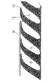
【図1】プラスチック・フィルム、紙またはテキスタイルのような移動している可撓性ストリップ材料を広げるためのストレッチャ・ローラの断面図である。
【図2】図1のローラの側面図である。
【図3】ローラの別の実施形態の拡大断面図である。
【符号の説明】
1 ローラ・ボディ
2 支持ピンまたはトラニオン
3 カバー
4 円筒形外面
5 長手軸線
6 切り込み
7 半径方向中央平面
10 側面
11 側面
12 底面
13 移行部
14 移行部
15 縁領域
16 ストリップ材料
17 くぼみ領域[0001]
The present invention relates to a stretcher roller for spreading a moving flexible strip material such as plastic film, paper or textile.
[0002]
Such a stretcher roller is known from DEA29522011. This includes a rigid roller body having support spindles at both ends thereof. A cover of elastomeric material is attached to the roller body. The elastomeric cover has a cut extending inwardly from its surface. These incisions are inclined with respect to the longitudinal axis of the roller body. These incisions are also inclined from the inside to the outside on each side of the radial center plane from the inside of the roller towards the respective adjacent outer ends of the roller. The incisions provided on each side of the radial center plane of the roller are in the form of a matching spiral. Each spiral is undercut. Each helix extends from the central plane toward the respective outer end of the roller. The inner ends of the spiral cuts are angularly offset with respect to each other so that the inner ends of the spirals are not located side by side with each other. The inner ends of the spiral cuts are actually offset by 180 degrees with respect to each other.
[0003]
The cut is bounded by arcuate side surfaces, and the bottom of the cut is rounded. The transition from the roller surface into the notch is rounded or chamfered on one side. On the other side, it has a sharp edge. These sharp edges make a groove angle of less than 90 degrees. The rounded transition of one notch is spatially farther from the radial center plane than the sharp edge transition of the same notch.
[0004]
The roller body may have a non-cylindrical part so that the spreading action is not insufficient in the central region. For the same reason, the stretcher roller may be provided with a vertical cut in the central part of the covering.
[0005]
The rounded transition prevents sharp edges from causing any squeezing or deflection of the strip material. Due to the spiral shape of the cut and its inclination, the strip material can be stretched uniformly and well during operation.
Nevertheless, this stretcher roller can be deflected or distorted, particularly in the edge region of the film.
[0006]
It is an object of the present invention to provide a stretcher roller that avoids the aforementioned deflections or distortions in a thin strip material during operation.
[0007]
In accordance with the present invention, the stretcher roller includes a roller body mounted for rotation about a longitudinal axis, the roller body having an outer surface of an elastomer material, the outer surface of the elastomer being substantially cylindrical. And having at least one incision inclined with respect to the longitudinal axis, and the transition surface from the outer surface into the incision has a groove angle of less than 90 degrees and is rounded. To do.
This avoids sharp edge transitions from the outer surface to the notch and reduces the deflection and distortion of the strip material.
[0008]
The cuts that are particularly affected are the cuts at each end of the roller. At these edges, the edge region of the film enters the cut. The edge area of the film could be damaged by sharp edges. This problem can be avoided by rounding or chamfering.
[0009]
Preferably, the outer surface does not have sharp edges, but the transition between the surface and the notch need only be rounded. Creases or deflections in the stretched strip material are best avoided by the rounded portion.
[0010]
Preferably, the central area of the outer surface is recessed, in particular by 0.1 to 0.5 millimeters. This recessed area is cylindrical as far as it is concerned, and preferably has a longitudinal dimension of 10 to 100 millimeters.
[0011]
It was found that when a load was applied to the roller body, the area on the surface of the roller far from the center plane was pressed relatively lightly by this load. During operation, the strip material is subjected to greater pressure in the intermediate region than in the edge region. This pressure difference affects the uniformity of the stretching action. Such uneven loading is avoided or at least reduced by providing indentations. The stretching action is thus improved. Also, such a recessed area can be manufactured easily and thus economically.
[0012]
Hereinafter, embodiments of the present invention will be described with reference to the accompanying drawings.
The stretcher roller of FIG. 1 includes a
[0013]
The cut is constituted by
[0014]
Flexures or creases caused by sharp edges are avoided by the rounded transition. In addition, the homogeneity of the spiral with respect to the slope of the notch allows for a uniform and good stretching of the strip material during operation.
[0015]
Near the
[0016]
The outer surface is substantially cylindrical, but in the region of the
[0017]
It was found that when a load was applied to the roller body, the surface area of the roller located far from the center plane was pressed relatively lightly by this load. Therefore, the strip material is exposed to greater pressure in the central region during operation than in the edge region. This pressure difference affects the uniformity of the stretching action. Indentation ensures that such uneven loads are avoided or at least reduced. Thus, the stretching action is improved. Also, the recessed area can be manufactured easily and therefore economically.
[0018]
The transition between the cylindrical outer surface 4 of the stretcher roller and the recessed
[0019]
FIG. 2 is an external view of the stretcher roller. The
[0020]
[0021]
FIG. 3 is an enlarged sectional view showing another embodiment of the
[Brief description of the drawings]
FIG. 1 is a cross-sectional view of a stretcher roller for spreading a moving flexible strip material such as plastic film, paper or textile.
FIG. 2 is a side view of the roller of FIG.
FIG. 3 is an enlarged cross-sectional view of another embodiment of a roller.
[Explanation of symbols]
DESCRIPTION OF
Claims (8)
前記エラストマ外面がほぼ円筒形であり、また、前記長手軸線に対して傾斜した少なくともローラの半径方向中央平面の各側に1つずつ、2つの切り込みが設けてあり、切り込みの各々が、それぞれ内側から外側へ、ローラの対応した端に向かって傾斜している、そして、前記エラストマ外面から前記切り込み内への移行表面が90度未満の開先角度をなし、丸くなっている、および
前記エラストマ外面の中央領域が0.1〜0.5ミリメートルくぼんでいる、
ストレッチャ・ローラ。Encompasses roller body mounted for rotation about the longitudinal axis, said roller body having an outer surface of the elastomeric material,
It said elastomeric outer surface is substantially cylindrical, also one on each side of the radial central plane of at least rollers are inclined relative to the longitudinal axis, Yes and two notches provided, each incision, inside each Inclined from the outer surface toward the corresponding end of the roller , and the transition surface from the outer surface of the elastomer into the incision has a groove angle of less than 90 degrees and is rounded, and
The central area of the outer surface of the elastomer is recessed by 0.1 to 0.5 millimeters;
Stretcher Laura.
Applications Claiming Priority (2)
| Application Number | Priority Date | Filing Date | Title |
|---|---|---|---|
| US09/536585 | 2000-03-28 | ||
| US09/536,585 US6145174A (en) | 2000-03-28 | 2000-03-28 | Stretcher roller |
Publications (2)
| Publication Number | Publication Date |
|---|---|
| JP2001277350A JP2001277350A (en) | 2001-10-09 |
| JP4698802B2 true JP4698802B2 (en) | 2011-06-08 |
Family
ID=24139104
Family Applications (1)
| Application Number | Title | Priority Date | Filing Date |
|---|---|---|---|
| JP2000260032A Expired - Fee Related JP4698802B2 (en) | 2000-03-28 | 2000-08-30 | Stretcher Laura |
Country Status (3)
| Country | Link |
|---|---|
| US (1) | US6145174A (en) |
| JP (1) | JP4698802B2 (en) |
| DE (1) | DE10111388A1 (en) |
Families Citing this family (9)
| Publication number | Priority date | Publication date | Assignee | Title |
|---|---|---|---|---|
| DE19906694C2 (en) * | 1999-02-18 | 2002-04-11 | Lueraflex Gmbh G Lueckenotto | Spreader roll |
| EP1176027B1 (en) * | 2000-07-27 | 2005-11-30 | Hewlett-Packard Company, A Delaware Corporation | Roller element for hardcopy apparatus |
| US20040154146A1 (en) * | 2001-05-17 | 2004-08-12 | Pruitt Paul R. | Web spreader roll and methods for spreading webs of material |
| US7004219B2 (en) * | 2002-10-11 | 2006-02-28 | The Boeing Company | Roller for automated fabric layup |
| CN100453315C (en) * | 2003-11-14 | 2009-01-21 | 拉佩·库特 | Method and apparatus for combination printing |
| US8087131B1 (en) * | 2010-08-19 | 2012-01-03 | Yuan-Long Cheng | Stretching assembly for cloth |
| CN102260976A (en) * | 2011-06-29 | 2011-11-30 | 吴江市新锦华纺织有限公司 | Spreading roller |
| DE102013001648A1 (en) * | 2012-02-17 | 2013-08-22 | Rolf Hessenbruch | Roller for guiding a flat track |
| US20150020494A1 (en) * | 2013-07-19 | 2015-01-22 | Ornek Makina Sanayi Ve Ticaret Limited Sirketi | Fiber unbundling assembly |
Family Cites Families (17)
| Publication number | Priority date | Publication date | Assignee | Title |
|---|---|---|---|---|
| US1435712A (en) * | 1921-10-25 | 1922-11-14 | Livesey Andrew | Spreading roller for web materials |
| US1563704A (en) * | 1924-09-02 | 1925-12-01 | Benninger Ag Maschf | Cloth-expanding roller |
| US1716555A (en) * | 1926-06-08 | 1929-06-11 | Thomas E Kane | Method of spreading or stretching material |
| US3545054A (en) * | 1966-05-23 | 1970-12-08 | Yoshikazu Sando | Method of longitudinally and laterally tensioning cloth |
| US3332131A (en) * | 1966-09-29 | 1967-07-25 | Howard E Weiler | Sleeve for fiberglass resin rollers |
| US3374648A (en) * | 1966-09-29 | 1968-03-26 | Crompton & Knowles Corp | Textile treating apparatus with a plastic coated or metal roll having left- and right-hand helical threads |
| US3528145A (en) * | 1968-10-31 | 1970-09-15 | Cluett Peabody & Co Inc | Split detector for fabrics undergoing incremental lateral stretching |
| US4566162A (en) * | 1982-10-26 | 1986-01-28 | American Roller Company | Stretcher/expander roller |
| CA1270786A (en) * | 1986-03-07 | 1990-06-26 | Akechi Yano | Roll with an arched shaft |
| JPS62209216A (en) * | 1986-03-07 | 1987-09-14 | Akitomo Yano | Curved-shaft roll |
| JPH0452217Y2 (en) * | 1987-02-04 | 1992-12-08 | ||
| JPH01152944U (en) * | 1988-04-13 | 1989-10-20 | ||
| US5188273A (en) * | 1989-02-03 | 1993-02-23 | Helmuth Schmoock | Expander roller for webs of paper and the like |
| DE4122121C2 (en) * | 1991-07-04 | 1993-11-11 | Kuesters Eduard Maschf | Wide stretching device |
| JP3463348B2 (en) * | 1994-05-27 | 2003-11-05 | ソニー株式会社 | Transport roll and method for manufacturing magnetic recording medium using the same |
| JP3823576B2 (en) * | 1998-12-10 | 2006-09-20 | 東レ株式会社 | Contact roll |
| JP2001139198A (en) * | 1999-11-11 | 2001-05-22 | Sony Corp | Sheet-shaped substrate width direction tension generating device, sheet-shaped substrate width direction tension generating method, and magnetic recording medium manufacturing apparatus |
-
2000
- 2000-03-28 US US09/536,585 patent/US6145174A/en not_active Expired - Fee Related
- 2000-08-30 JP JP2000260032A patent/JP4698802B2/en not_active Expired - Fee Related
-
2001
- 2001-03-09 DE DE10111388A patent/DE10111388A1/en not_active Withdrawn
Also Published As
| Publication number | Publication date |
|---|---|
| DE10111388A1 (en) | 2001-10-04 |
| JP2001277350A (en) | 2001-10-09 |
| US6145174A (en) | 2000-11-14 |
Similar Documents
| Publication | Publication Date | Title |
|---|---|---|
| JP4698802B2 (en) | Stretcher Laura | |
| US4059180A (en) | Roller assembly with improved mounting means | |
| US5503207A (en) | Pneumatic tire including lateral grooves | |
| AU627471B2 (en) | Belt conveyor with belt reinforcing member | |
| US10820771B2 (en) | Cleaning roller | |
| CA2342010C (en) | Holder for the mounting of a wiper mop to a handle | |
| KR20010031123A (en) | Opaque article with design pattern | |
| BRPI0706565B1 (en) | DUMP VALVE MOUNT FOR LINEAR COMPRESSOR | |
| KR100483173B1 (en) | Roll stand for rolling bands | |
| US11104092B2 (en) | Pressure roller for shaping tire member | |
| US4510868A (en) | Circumferentially continuous cylinder for a rotary printing machine | |
| US2338847A (en) | Method of making ribbed rolls for slashing machines and other textile machines | |
| JP5697817B2 (en) | Held made of plastic material | |
| US6511225B2 (en) | Calibrated sliding bearing bushing and calibrating tool for producing the sliding bearing bushing | |
| CN100379631C (en) | Punch cutter cover locking device | |
| US2285375A (en) | Ribbed roll for slashing machines and other textile machines | |
| US3462058A (en) | Self-adhering feed roll | |
| EP2557060A1 (en) | Paper sheet conveying roller | |
| US5125337A (en) | Printing cylinder groove filler | |
| JP2004068889A (en) | Sealing device | |
| US6792775B2 (en) | Latch needle | |
| JP7101271B2 (en) | Stitching roller for stitching strips | |
| US1818798A (en) | Pulley | |
| US3894565A (en) | Temple roller device | |
| US1953177A (en) | Cloth spreader or expander |
Legal Events
| Date | Code | Title | Description |
|---|---|---|---|
| A621 | Written request for application examination |
Free format text: JAPANESE INTERMEDIATE CODE: A621 Effective date: 20070709 |
|
| RD04 | Notification of resignation of power of attorney |
Free format text: JAPANESE INTERMEDIATE CODE: A7424 Effective date: 20090929 |
|
| A977 | Report on retrieval |
Free format text: JAPANESE INTERMEDIATE CODE: A971007 Effective date: 20100128 |
|
| A131 | Notification of reasons for refusal |
Free format text: JAPANESE INTERMEDIATE CODE: A131 Effective date: 20100209 |
|
| A521 | Request for written amendment filed |
Free format text: JAPANESE INTERMEDIATE CODE: A523 Effective date: 20100510 |
|
| RD12 | Notification of acceptance of power of sub attorney |
Free format text: JAPANESE INTERMEDIATE CODE: A7432 Effective date: 20100510 |
|
| A521 | Request for written amendment filed |
Free format text: JAPANESE INTERMEDIATE CODE: A821 Effective date: 20100510 |
|
| A01 | Written decision to grant a patent or to grant a registration (utility model) |
Free format text: JAPANESE INTERMEDIATE CODE: A01 Effective date: 20110215 |
|
| A61 | First payment of annual fees (during grant procedure) |
Free format text: JAPANESE INTERMEDIATE CODE: A61 Effective date: 20110302 |
|
| LAPS | Cancellation because of no payment of annual fees |