JP4716100B2 - 気圧式倍力装置 - Google Patents
気圧式倍力装置 Download PDFInfo
- Publication number
- JP4716100B2 JP4716100B2 JP2005287642A JP2005287642A JP4716100B2 JP 4716100 B2 JP4716100 B2 JP 4716100B2 JP 2005287642 A JP2005287642 A JP 2005287642A JP 2005287642 A JP2005287642 A JP 2005287642A JP 4716100 B2 JP4716100 B2 JP 4716100B2
- Authority
- JP
- Japan
- Prior art keywords
- piston
- plunger
- elastic member
- reaction
- spring
- Prior art date
- Legal status (The legal status is an assumption and is not a legal conclusion. Google has not performed a legal analysis and makes no representation as to the accuracy of the status listed.)
- Expired - Fee Related
Links
Images


Landscapes
- Braking Systems And Boosters (AREA)
Description
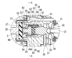
前記リアクション部材に対向するピストンと、該ピストンと前記プランジャとの間に介装された弾性部材と、前記ピストン、前記弾性部材及び前記プランジャの外周に摺動可能に嵌合して前記弾性部材の拡径を制限する小径円筒部と前記弾性部材の拡径を許容する大径円筒部とを有する段付スリーブと、前記ピストンの前記リアクション部材側の端面に係合する取付部と該取付部から前記段付スリーブの外周側を通って前記プランジャ側へ延びる複数のアーム部と該アーム部の先端部から径方向内側へ突出された爪部とを有するスプリングホルダと、前記段付スリーブの段部と前記爪部との間に介装されて前記段付スリーブを前記リアクション部材側へ付勢するスプリングとを備え、前記段付スリーブは、通常、前記スプリングの付勢力によって前記小径円筒部が前記弾性部材の拡径を制限する位置にあり、前記プランジャの前記バルブボディに対する速度又は移動量が所定値に達したとき、前記スプリングの付勢力に抗して移動して前記大径円筒部が前記弾性部材の拡径を許容するブレーキアシスト機構が設けられていることを特徴とする。
図1及び図3に示すように、本実施形態に係る気圧式倍力装置16は、タンデム型気圧式倍力装置であって、シェル17(ハウジング)の内部が隔壁18によって前室19と後室20との2室に区画されている。前室19及び後室20は、それぞれパワーピストン21、22によって定圧室19A、20Aと変圧室19B、20Bとに画成されている。定圧室19A、20A間及び変圧室19B、20B間は、それぞれ通路23、24によって連通されている。パワーピストン21、22には、略円筒状のバルブボディ25が連結されて、バルブボディ25は、シェル17の隔壁18及び後壁26に摺動可能かつ気密的に挿通されており、その後端部が後壁26から外部へ延出されている。バルブボディ25の前部には、リアクションディスク27(リアクション部材)を介して出力ロッド28が連結されており、出力ロッド28の先端部は、シェル17の前壁に取付けられるマスタシリンダ(図示せず)のピストンに連結される。
ブレーキアシスト機構29は、リアクションディスク27に当接するピストン44と、プランジャ30に当接する弾性部材45と、これらの外周に取付けられた段付スリーブ46と、スプリング47と、スプリングホルダ48とを備えている。
図1に示す非制動状態においては、ポペットシール31がシート部34、35に着座して、変圧室19B、20Bが大気及び定圧室19A、20A(負圧)から遮断されて、定圧室19A、20Aと変圧室19B、20Bと圧力が釣合っており、パワーピストン21、22に推力が発生しない。
Claims (1)
- ハウジング内をパワーピストンによって定圧室と変圧室とに画成し、前記パワーピストンに連結したバルブボディ内に配置したプランジャを入力ロッドによって移動させることにより、弁手段を開いて前記変圧室に作動気体を導入して前記定圧室と変圧室との間に圧力差を発生させ、この圧力差によって前記パワーピストンに生じた推力をリアクション部材を介して出力ロッドに作用させるとともに、該出力ロッドから前記リアクション部材に作用する反力の一部を前記入力ロッドに伝達するようにした気圧式倍力装置において、
前記リアクション部材に対向するピストンと、該ピストンと前記プランジャとの間に介装された弾性部材と、前記ピストン、前記弾性部材及び前記プランジャの外周に摺動可能に嵌合して前記弾性部材の拡径を制限する小径円筒部と前記弾性部材の拡径を許容する大径円筒部とを有する段付スリーブと、前記ピストンの前記リアクション部材側の端面に係合する取付部と該取付部から前記段付スリーブの外周側を通って前記プランジャ側へ延びる複数のアーム部と該アーム部の先端部から径方向内側へ突出された爪部とを有するスプリングホルダと、前記段付スリーブの段部と前記爪部との間に介装されて前記段付スリーブを前記リアクション部材側へ付勢するスプリングとを備え、前記段付スリーブは、通常、前記スプリングの付勢力によって前記小径円筒部が前記弾性部材の拡径を制限する位置にあり、前記プランジャの前記バルブボディに対する速度又は移動量が所定値に達したとき、前記スプリングの付勢力に抗して移動して前記大径円筒部が前記弾性部材の拡径を許容するブレーキアシスト機構が設けられていることを特徴とする気圧式倍力装置。
Priority Applications (1)
| Application Number | Priority Date | Filing Date | Title |
|---|---|---|---|
| JP2005287642A JP4716100B2 (ja) | 2005-09-30 | 2005-09-30 | 気圧式倍力装置 |
Applications Claiming Priority (1)
| Application Number | Priority Date | Filing Date | Title |
|---|---|---|---|
| JP2005287642A JP4716100B2 (ja) | 2005-09-30 | 2005-09-30 | 気圧式倍力装置 |
Publications (2)
| Publication Number | Publication Date |
|---|---|
| JP2007098970A JP2007098970A (ja) | 2007-04-19 |
| JP4716100B2 true JP4716100B2 (ja) | 2011-07-06 |
Family
ID=38026357
Family Applications (1)
| Application Number | Title | Priority Date | Filing Date |
|---|---|---|---|
| JP2005287642A Expired - Fee Related JP4716100B2 (ja) | 2005-09-30 | 2005-09-30 | 気圧式倍力装置 |
Country Status (1)
| Country | Link |
|---|---|
| JP (1) | JP4716100B2 (ja) |
Families Citing this family (2)
| Publication number | Priority date | Publication date | Assignee | Title |
|---|---|---|---|---|
| JP5333726B2 (ja) * | 2008-10-31 | 2013-11-06 | 日立オートモティブシステムズ株式会社 | 気圧式倍力装置 |
| JP6155502B2 (ja) * | 2013-04-17 | 2017-07-05 | 日立オートモティブシステムズ株式会社 | 気圧式倍力装置 |
Family Cites Families (3)
| Publication number | Priority date | Publication date | Assignee | Title |
|---|---|---|---|---|
| JPH0341421U (ja) * | 1989-08-29 | 1991-04-19 | ||
| JP3041421U (ja) * | 1997-03-12 | 1997-09-19 | 日本エービーエス株式会社 | 流体圧制御弁 |
| JP3928158B2 (ja) * | 2002-01-31 | 2007-06-13 | 株式会社日立製作所 | 気圧式倍力装置 |
-
2005
- 2005-09-30 JP JP2005287642A patent/JP4716100B2/ja not_active Expired - Fee Related
Also Published As
| Publication number | Publication date |
|---|---|
| JP2007098970A (ja) | 2007-04-19 |
Similar Documents
| Publication | Publication Date | Title |
|---|---|---|
| JP5321803B2 (ja) | 気圧式倍力装置 | |
| JP2004051078A (ja) | 気圧式倍力装置 | |
| JP4206877B2 (ja) | 気圧式倍力装置 | |
| JP2007098970A (ja) | 気圧式倍力装置 | |
| JP6155502B2 (ja) | 気圧式倍力装置 | |
| US7063002B2 (en) | Negative pressure type booster | |
| GB2032552A (en) | Vacuum brake boosters | |
| JP5078796B2 (ja) | 負圧ブースタ | |
| JPH10230840A (ja) | 気圧式倍力装置 | |
| JP4626773B2 (ja) | 気圧式倍力装置 | |
| JP4626772B2 (ja) | 気圧式倍力装置 | |
| JP6179425B2 (ja) | 気圧式倍力装置 | |
| US7472968B2 (en) | Vacuum type brake booster | |
| JP4583932B2 (ja) | 補助ブレーキのための空圧サーボモータ及びその製造方法及び製造装置 | |
| JP6297318B2 (ja) | 気圧式倍力装置 | |
| JP2020011609A (ja) | 気圧式倍力装置 | |
| JP2004058861A (ja) | 気圧式倍力装置 | |
| KR100916397B1 (ko) | 차량용 브레이크 부스터 | |
| WO2016203892A1 (ja) | 倍力装置 | |
| JP6260769B2 (ja) | 負圧式倍力装置 | |
| KR100673056B1 (ko) | 차량용 부스터 | |
| JP2019006300A (ja) | 気圧式倍力装置 | |
| JP3885178B2 (ja) | 気圧式倍力装置 | |
| JP2817765B2 (ja) | 倍力装置 | |
| JP3931275B2 (ja) | ブレーキ装置および倍力装置 |
Legal Events
| Date | Code | Title | Description |
|---|---|---|---|
| A621 | Written request for application examination |
Free format text: JAPANESE INTERMEDIATE CODE: A621 Effective date: 20080627 |
|
| A521 | Request for written amendment filed |
Free format text: JAPANESE INTERMEDIATE CODE: A821 Effective date: 20080630 |
|
| A711 | Notification of change in applicant |
Free format text: JAPANESE INTERMEDIATE CODE: A712 Effective date: 20090902 |
|
| RD03 | Notification of appointment of power of attorney |
Free format text: JAPANESE INTERMEDIATE CODE: A7423 Effective date: 20090902 |
|
| A521 | Request for written amendment filed |
Free format text: JAPANESE INTERMEDIATE CODE: A523 Effective date: 20090904 |
|
| A977 | Report on retrieval |
Free format text: JAPANESE INTERMEDIATE CODE: A971007 Effective date: 20100218 |
|
| A131 | Notification of reasons for refusal |
Free format text: JAPANESE INTERMEDIATE CODE: A131 Effective date: 20100929 |
|
| A521 | Request for written amendment filed |
Free format text: JAPANESE INTERMEDIATE CODE: A523 Effective date: 20101126 |
|
| TRDD | Decision of grant or rejection written | ||
| A01 | Written decision to grant a patent or to grant a registration (utility model) |
Free format text: JAPANESE INTERMEDIATE CODE: A01 Effective date: 20110309 |
|
| A01 | Written decision to grant a patent or to grant a registration (utility model) |
Free format text: JAPANESE INTERMEDIATE CODE: A01 |
|
| A61 | First payment of annual fees (during grant procedure) |
Free format text: JAPANESE INTERMEDIATE CODE: A61 Effective date: 20110316 |
|
| R150 | Certificate of patent or registration of utility model |
Free format text: JAPANESE INTERMEDIATE CODE: R150 Ref document number: 4716100 Country of ref document: JP Free format text: JAPANESE INTERMEDIATE CODE: R150 |
|
| FPAY | Renewal fee payment (event date is renewal date of database) |
Free format text: PAYMENT UNTIL: 20140408 Year of fee payment: 3 |
|
| R250 | Receipt of annual fees |
Free format text: JAPANESE INTERMEDIATE CODE: R250 |
|
| LAPS | Cancellation because of no payment of annual fees |