JP4720587B2 - Ultrasonic sensor - Google Patents
Ultrasonic sensor Download PDFInfo
- Publication number
- JP4720587B2 JP4720587B2 JP2006107291A JP2006107291A JP4720587B2 JP 4720587 B2 JP4720587 B2 JP 4720587B2 JP 2006107291 A JP2006107291 A JP 2006107291A JP 2006107291 A JP2006107291 A JP 2006107291A JP 4720587 B2 JP4720587 B2 JP 4720587B2
- Authority
- JP
- Japan
- Prior art keywords
- case
- circuit board
- ultrasonic transducer
- pin
- hole
- Prior art date
- Legal status (The legal status is an assumption and is not a legal conclusion. Google has not performed a legal analysis and makes no representation as to the accuracy of the status listed.)
- Expired - Lifetime
Links
Images


Classifications
-
- G—PHYSICS
- G10—MUSICAL INSTRUMENTS; ACOUSTICS
- G10K—SOUND-PRODUCING DEVICES; METHODS OR DEVICES FOR PROTECTING AGAINST, OR FOR DAMPING, NOISE OR OTHER ACOUSTIC WAVES IN GENERAL; ACOUSTICS NOT OTHERWISE PROVIDED FOR
- G10K9/00—Devices in which sound is produced by vibrating a diaphragm or analogous element, e.g. fog horns, vehicle hooters or buzzers
- G10K9/18—Details, e.g. bulbs, pumps, pistons, switches or casings
- G10K9/22—Mountings; Casings
Landscapes
- Physics & Mathematics (AREA)
- Engineering & Computer Science (AREA)
- Acoustics & Sound (AREA)
- Multimedia (AREA)
- Transducers For Ultrasonic Waves (AREA)
- Measurement Of Velocity Or Position Using Acoustic Or Ultrasonic Waves (AREA)
Description
本発明は、圧電素子を有して構成される超音波振動子が備えられた超音波センサに関するものである。 The present invention relates to an ultrasonic sensor provided with an ultrasonic transducer having a piezoelectric element.
従来、圧電素子を有して構成される超音波振動子が備えられた超音波センサとして、例えば、特許文献1に示されるものがある。この特許文献1に示される超音波センサは、有底筒状のハウジングの底部内面に圧電素子を貼着してなる超音波振動子と、開口面を有し、超音波振動子がその開口面から挿入されて内部に組み付けられるケースとにより構成される。そして、圧電素子は、リードを介して、ケースの内部に配置された回路基板(処理回路)と電気的に接続されている。 Conventionally, as an ultrasonic sensor provided with an ultrasonic transducer having a piezoelectric element, there is one disclosed in Patent Document 1, for example. The ultrasonic sensor disclosed in Patent Document 1 includes an ultrasonic transducer formed by attaching a piezoelectric element to the inner surface of the bottom of a bottomed cylindrical housing, and an opening surface. And a case that is inserted and assembled inside. The piezoelectric element is electrically connected to a circuit board (processing circuit) disposed inside the case via a lead.
それに対し、近年、作業性向上のため、リードに代えて接続ピンを使用した超音波センサの要求が高まっている。このため、例えば特許文献2、3では、圧電素子に対して接続ピンを電気的に接続すると共に、ハウジングの下部に絶縁材料からなるベース(端子板)を固定し、接続ピンの一端がベースを貫通してハウジングの外部に引き出される構造の超音波振動子が提案されている。このような接続ピンを用いることで、超音波振動子をケースの開口面に挿入したときに、回路基板に形成されるスルーホールに直接接続ピンの先端が挿入されるようにできる。
超音波振動子は、超音波を発生させるときに振動するため、この振動がケースに伝わらないようにするために、ケースの開口面に対して直接固定されるのではなく、有底筒状を為した筒状弾性体が被着された状態で固定される。つまり、超音波振動子の外周面および底面とケースの開口面との間には筒状弾性体が配置され、筒状弾性体にて振動を吸収することでケースに振動が伝わらないようにしている。 Since the ultrasonic vibrator vibrates when generating ultrasonic waves, in order to prevent this vibration from being transmitted to the case, it is not directly fixed to the opening surface of the case, but has a bottomed cylindrical shape. The formed cylindrical elastic body is fixed in a state where it is attached. In other words, a cylindrical elastic body is disposed between the outer peripheral surface and bottom surface of the ultrasonic vibrator and the opening surface of the case, and the vibration is not transmitted to the case by absorbing the vibration with the cylindrical elastic body. Yes.
しかしながら、筒状弾性体が柔らかいため、バンパー等に超音波センサを取り付けた後、外部から超音波振動子が押された場合、筒状弾性体が弾性変形し、超音波振動子が開口面内に押し込まれる。このため、超音波振動子に備えられた接続ピンも押し込まれることになり、接続ピンと回路基板の電気的な接続を行っている例えばはんだ付け部分に応力が掛かり、これらの間の電気的な接続が破壊されるという問題がある。 However, since the cylindrical elastic body is soft, when the ultrasonic transducer is pressed from the outside after the ultrasonic sensor is attached to a bumper or the like, the cylindrical elastic body is elastically deformed, and the ultrasonic transducer is in the opening plane. Is pushed into. For this reason, the connection pin provided in the ultrasonic transducer is also pushed in, and stress is applied to, for example, the soldering portion that performs the electrical connection between the connection pin and the circuit board, and the electrical connection between them. There is a problem that will be destroyed.
特に、ハウジングの下部に配置されたベースの下側に、さらに振動を抑制する弾性体となる発泡弾性体が配置されるような構造とされる場合、超音波振動子が押されたときに押し込まれる量が大きいため、より上記問題が顕著になる。 In particular, when a foamed elastic body that is an elastic body that further suppresses vibration is disposed below the base disposed at the lower part of the housing, it is pushed in when the ultrasonic transducer is pressed. The above problem becomes more prominent because of the large amount.
本発明は上記点に鑑みて、超音波振動子が押し込まれたときに圧電素子と回路基板との電気的な接続が破壊されないようにできる超音波センサを提供することを目的とする。 An object of the present invention is to provide an ultrasonic sensor capable of preventing the electrical connection between a piezoelectric element and a circuit board from being broken when an ultrasonic transducer is pushed.
上記目的を達成するため、本発明では、ケース(30)における中空部に露出し、該露出した部分が接続ピン(15)に電気的に接続されると共に、接続ピン(15)が超音波振動子(10)を開口面(32)に挿入する方向に押し込まれると、該方向に撓む中継ピン(21)を備え、この中継ピン(21)を介して、回路基板(20)が圧電素子(12)と電気的に接続されるようにすることを特徴としている。 In order to achieve the above object, according to the present invention, the hollow portion of the case (30) is exposed, the exposed portion is electrically connected to the connection pin (15), and the connection pin (15) is subjected to ultrasonic vibration. When the child (10) is pushed in the direction of insertion into the opening surface (32), a relay pin (21) that bends in this direction is provided, and the circuit board (20) is connected to the piezoelectric element via the relay pin (21). It is characterized in that it is electrically connected to (12).
このように、接続ピン(15)が回路基板(20)に直接接続されるのではなく、中継ピン(21)を介して回路基板(20)に接続されるようにしている。このため、超音波振動子(10)が外部から押されることで接続ピン(15)が押し込まれても、そのとき発生する応力を中継ピン(21)にて吸収することが可能となる。このため、超音波振動子(10)が押し込まれたときに圧電素子(12)と回路基板(20)との電気的な接続が破壊されないようにできる。 Thus, the connection pin (15) is not directly connected to the circuit board (20), but is connected to the circuit board (20) via the relay pin (21). For this reason, even if the connection pin (15) is pushed in by pushing the ultrasonic transducer (10) from the outside, the stress generated at that time can be absorbed by the relay pin (21). For this reason, it is possible to prevent the electrical connection between the piezoelectric element (12) and the circuit board (20) from being broken when the ultrasonic transducer (10) is pushed.
例えば、中継ピンは、ケース(30)にインサート成形されたインサートピン(21)とされ、該インサートピン(21)の一端をケース(30)の中空部に露出させた構成とされる。 For example, the relay pin is an insert pin (21) insert-molded in the case (30), and one end of the insert pin (21) is exposed in the hollow portion of the case (30).
この場合、インサートピン(21)の一端に穴部(21a)を設け、超音波振動子(10)をケース(30)に組み付けたときに、接続ピン(15)のうちハウジング(11)の外部に引き出された一端が穴部(21a)に挿入されるように、接続ピン(15)および穴部(21a)の位置を設定すると好ましい。 In this case, when a hole (21a) is provided at one end of the insert pin (21) and the ultrasonic vibrator (10) is assembled to the case (30), the housing (11) of the connection pin (15) It is preferable to set the positions of the connection pin (15) and the hole (21a) so that one end pulled out into the hole is inserted into the hole (21a).
このように、インサートピン(21)の穴部(21a)の配置場所を接続ピン(15)の先端位置と一致させれば、超音波振動子(10)をケース(30)の開口面(32)に挿入したときに、接続ピン(15)がそのままインサートピン(21)の穴部(21a)に挿入される。これにより、超音波センサの組み付け作業性を向上させることが可能となる。 As described above, when the arrangement position of the hole (21a) of the insert pin (21) is made to coincide with the tip position of the connection pin (15), the ultrasonic transducer (10) is moved to the opening surface (32) of the case (30). ), The connection pin (15) is inserted into the hole (21a) of the insert pin (21) as it is. Thereby, it is possible to improve the workability of assembling the ultrasonic sensor.
例えば、ケース(30)における超音波振動子(10)が配置される開口面(32)と回路基板(20)が配置される中空部とを区画し、接続ピン(15)が挿入される位置決め用穴(31a)が形成されたガイド部(31)を備え、接続ピン(15)のうちハウジング(11)の外部に引き出された一端を位置決め用穴(31a)に挿入すると、穴部(21a)に挿入されるような構成とすることができる。 For example, the opening (32) in which the ultrasonic transducer (10) is arranged in the case (30) and the hollow part in which the circuit board (20) is arranged are partitioned, and positioning in which the connection pin (15) is inserted. When the guide part (31) in which the hole (31a) is formed is provided and one end pulled out of the housing (11) of the connection pin (15) is inserted into the positioning hole (31a), the hole part (21a ).
また、超音波振動子(10)に備えられた、該超音波振動子(10)の外周面よりも該超音波振動子(10)の径方向に突出した第1の基準部(14a)と、筒状弾性体(33)の外周面(33b)に形成された第2の基準部(33c)と、ケース(30)における開口面(32)の内壁に形成された第3の基準部(38)と、を備える。このような構成によれば、第1の基準部(14a)と第2の基準部(33c)とを位置合わせして筒状弾性体(33)を超音波振動子(10)に被着した状態で、第1、第2の基準部(14a、33c)と第3の基準部(38)とを位置合わせして超音波振動子(10)を開口面(32)に挿入する構成にできる。 Further, a first reference portion (14a) provided in the ultrasonic transducer (10) and projecting in the radial direction of the ultrasonic transducer (10) from the outer peripheral surface of the ultrasonic transducer (10); The second reference portion (33c) formed on the outer peripheral surface (33b) of the cylindrical elastic body (33) and the third reference portion (on the inner wall of the opening surface (32) in the case (30)) 38). According to such a configuration, the first reference portion (14a) and the second reference portion (33c) are aligned, and the cylindrical elastic body (33) is attached to the ultrasonic transducer (10). In this state, the first and second reference portions (14a, 33c) and the third reference portion (38) are aligned, and the ultrasonic transducer (10) is inserted into the opening surface (32). .
また、インサートピン(21)の他端(21b)が回路基板(20)をケース(30)の中空部に挿入する方向と平行に引き出された構成とし、回路基板(20)をケース(30)の中空部に挿入したときに、インサートピン(21)の他端(21b)が回路基板(20)に備えられた第1スルーホール(20a)に挿入されるように、インサートピン(21)の他端および回路基板(20)に備えられた第1スルーホール(20a)の位置を設定すると好ましい。 Further, the other end (21b) of the insert pin (21) is drawn out in parallel with the direction in which the circuit board (20) is inserted into the hollow portion of the case (30), and the circuit board (20) is drawn into the case (30). Of the insert pin (21) so that the other end (21b) of the insert pin (21) is inserted into the first through hole (20a) provided in the circuit board (20) when inserted into the hollow portion of the insert pin (21). It is preferable to set the position of the first through hole (20a) provided in the other end and the circuit board (20).
このように、インサートピン(21)の他端(21b)を回路基板(20)の第1スルーホール(20a)と一致させれば、ケース(30)に回路基板(20)を挿入したときに、インサートピン(21)の他端(21b)が回路基板(20)の第1スルーホール(20a)に挿入される。これにより、超音波センサの組み付け作業性を向上させることが可能となる。 As described above, when the other end (21b) of the insert pin (21) is aligned with the first through hole (20a) of the circuit board (20), the circuit board (20) is inserted into the case (30). The other end (21b) of the insert pin (21) is inserted into the first through hole (20a) of the circuit board (20). Thereby, it is possible to improve the workability of assembling the ultrasonic sensor.
さらに、ケース(30)に回路基板(20)の第2スルーホール(20b)に挿入されることで回路基板(20)と電気的に接続される外部出力端子(36)を備え、該外部出力端子(36)のうち回路基板(20)に接続される一端(36a)を回路基板(20)をケース(30)の中空部に挿入する方向と平行に引き出し、回路基板(20)をケース(30)の中空部に挿入したときに、外部出力端子(36)の一端(36a)が回路基板(20)に備えられた第2スルーホール(20b)に挿入されるように、外部出力端子(36)の一端(36a)および回路基板(20)に備えられた第2スルーホール(20b)の位置を設定すると好ましい。 The case (30) further includes an external output terminal (36) that is electrically connected to the circuit board (20) by being inserted into the second through hole (20b) of the circuit board (20). One end (36a) of the terminal (36) connected to the circuit board (20) is pulled out in parallel with the direction in which the circuit board (20) is inserted into the hollow portion of the case (30), and the circuit board (20) is removed from the case ( 30), the external output terminal (36a) is inserted into the second through hole (20b) provided in the circuit board (20) so that the external output terminal (36a) is inserted into the second through hole (20b). It is preferable to set the position of one end (36a) of 36) and the second through hole (20b) provided in the circuit board (20).
このように、外部出力端子(36)の一端(36a)を回路基板(20)の第2スルーホール(20b)と一致させれば、ケース(30)に回路基板(20)を挿入したときに、外部出力端子(36)の一端(36a)が回路基板(20)の第2スルーホール(20b)に挿入される。これにより、超音波センサの組み付け作業性を向上させることが可能となる。 Thus, if one end (36a) of the external output terminal (36) is made to coincide with the second through hole (20b) of the circuit board (20), the circuit board (20) is inserted into the case (30). The one end (36a) of the external output terminal (36) is inserted into the second through hole (20b) of the circuit board (20). Thereby, it is possible to improve the workability of assembling the ultrasonic sensor.
なお、上記各手段の括弧内の符号は、後述する実施形態に記載の具体的手段との対応関係を示すものである。 In addition, the code | symbol in the bracket | parenthesis of each said means shows the correspondence with the specific means as described in embodiment mentioned later.
以下、本発明の実施形態について図に基づいて説明する。なお、以下の各実施形態相互において、互いに同一もしくは均等である部分には、図中、同一符号を付してある。 Hereinafter, embodiments of the present invention will be described with reference to the drawings. In the following embodiments, the same or equivalent parts are denoted by the same reference numerals in the drawings.
(第1実施形態)
本実施形態の第1実施形態にかかる超音波センサについて説明する。本実施形態の超音波ソナーは、例えば、車両のバンパに取り付けられ、バックソナー又はコーナーソナーとして用いられる。
(First embodiment)
The ultrasonic sensor according to the first embodiment of the present embodiment will be described. The ultrasonic sonar of this embodiment is attached to a bumper of a vehicle, for example, and used as a back sonar or a corner sonar.
図1に、本実施形態の超音波センサを構成する超音波振動子10を示す。図1(a)は、超音波振動子10の断面図、図1(b)は、超音波振動子10に備えられる圧電素子12を収容したハウジング11の裏面図、図1(c)は、超音波振動子10全体の裏面図、図1(d)は、超音波振動子10の側面図である。なお、図1(a)は、図1(c)におけるA−A矢視断面に相当する。
FIG. 1 shows an
図1(a)〜(d)に示すように、超音波振動子10は、ハウジング11、圧電素子12と、スペーサ13、ベース14および接続ピン15を有して構成されている。
As shown in FIGS. 1A to 1D, the
ハウジング11は、導電性材料(金属材料や表面に導電膜を形成した絶縁材料)で構成され、有底円筒状とされることでハウジング11の内部に内部空間16が形成されている。ハウジング11の底部11aの内面に圧電素子12が貼着されており、この底部11aの外側表面が振動面11bとなっている。本実施形態では、導電性材料としてアルミニウムを用いており、振動面11bを円形状としている。また、内部空間16の上面形状は、図1(b)に示すように、長辺と短辺が異なる長さで、四隅が丸められた長方形状とされている。内部空間16をこのような形状とすることにより、超音波振動子10の指向性を水平方向と垂直方向とで異なるものとすることができる。なお、図1(b)においては、上下方向が指向性の狭い垂直方向、左右方向が指向性の広い水平方向となっている。
The
圧電素子12は、圧電セラミックス(例えばチタン酸ジルコン酸鉛系)で構成され、その表裏両面に電極(図示せず)を備えている。圧電素子12の一方の電極は、リード17aによって一対の接続ピン15の一方に電気的に接続され、他方の電極は、ハウジング11の底部11aに例えば導電性接着剤により貼着され、導電性材料で構成されたハウジング11を介してリード17bに接続されたのち、一対の接続ピン15の他方に電気的に接続されている。なお、ハウジング11の内部空間16には、スペーサ13及びベース14に設けられた注入口(図示略)を介して、圧電素子12側から順にフェルト、シリコンが充填されており、振動面から接続ピン15に伝達される不要振動が抑制されている。
The
スペーサ13は、ハウジング11の開口部とベース14との間に配置されている。スペーサ13は、ハウジング11の底部11aの振動に伴ってハウジング11の筒部11cに生じる不要振動が接続ピン15の固定されているベース14に伝達されるのを抑制するための弾性体であり、例えばシリコンゴムから構成されている。なお、ここではスペーサ13を配置する構成としたが、スペーサ13を無くした構成とすることもできる。
The
ベース14は、ハウジング11の開口部側の外周面にスペーサ13を介して嵌め込まれることで、ハウジング11に固定されている。このベース14は、絶縁材料、例えば合成樹脂(例えばABS樹脂)で構成されている。ベース14には、接続ピン15が貫通配置されている。ベース14を成形する際に、接続ピン15をインサート成形することで、接続ピン15の一部がベース14に埋設固定されるようにしている。また、ベース14には、接続ピン15の長手方向沿って延設された保護部18が備えられ、ハウジング11の外部に引き出された接続ピン15を、ベース14からハウジング外部の先端に向けて所定範囲被覆している。この保護部18にて、一対の接続ピン15が一体的に被覆されている。
The
また、ベース14には、接続ピン15が突出する方向に突出する第1の基準部14aが形成されている。第1の基準部14aの先端位置は、図1(c)、(d)に示すように、ベース14の外周面に対してベース14(超音波振動子10)の径方向において部分的に突出させられている。
The
接続ピン15は、例えば銅を主成分とする導電性材料からなり、例えば太さ0.5mmφの棒状部材で構成される。本実施形態では、超音波振動子10(圧電素子12)の指向性が水平方向と垂直方向とで異なるように構成してあるため、接続ピン15および保護部18を、図1(c)に示すように、超音波振動子10(ハウジング11)の中心軸からずれた位置に設けている。
The
なお、本実施形態では、ベース14の一部で保護部18を構成したが、保護部18をベース14と別部材として構成しても良い。例えば、ベース14に接着等によって保護部18を固定した構成としても良い。また、保護部18により、一対の接続ピン15を一体的に被覆せず、各接続ピン15毎に独立して被覆保護する構成であっても良い。また、ベース14及び保護部18に対する接続ピン15の貫通配置としては、上記インサートに限定されるものではなく、接続ピン15がベース14及び保護部18に設けられた貫通孔に対して挿通され、所定配置となった状態で接着固定されたものでも良い。ただし、本実施形態の構成とすると、接続ピン15の湾曲や折曲等の防止に効果的である。
In the present embodiment, the
さらに、超音波振動子10には、例えば発泡シリコン等で構成された発泡弾性体19が備えられている。この発泡弾性体19は、保護部18に対向するベース14上に振動を抑制する弾性体として機能するもので、接続ピン15は発泡弾性体19も貫通するように配置されている。なお、ここでは発泡弾性体19を備えた構成としているが、備えていない構造とすることもできる。
Further, the
そして、ハウジング11、スペーサ13、ベース14、発泡弾性体19が、それぞれ接着剤(例えばシリコン系接着剤)等で接着されることで、一体構造とされた超音波振動子10が構成されている。
The
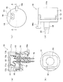
図2は、図1に示す超音波振動子10が備えられた超音波センサ100の概略構成を示した図であり、図2(a)は断面図、図2(b)は超音波センサ100の回路基板20などが収容されるケース30を裏面側から見た図である。なお、図2(a)では、便宜上、回路基板20を構成する電子部品を省略して図示してある。
2A and 2B are diagrams showing a schematic configuration of the
超音波センサ100は、上述した超音波振動子10と、超音波を発生させる駆動電圧を超音波振動子10に印加するとともに、超音波振動子10から逆起電圧効果により発生した電圧を処理する回路基板20とが、合成樹脂からなるケース30内に組み付けられて構成されている。
The
中空状のケース30内には、回路基板20の接続位置に対して接続ピン15を位置決めするために、保護部18を位置決めするガイド部31が設けられている。本実施形態では、ガイド部31は、ケース30の一部として構成されている。
In the
ガイド部31は、ケース30の内部空間を超音波振動子10の配置空間と回路基板20の配置空間とに区画する板状部によって構成され、保護部18が挿入される位置決め用穴31aが備えられた構成とされている。この位置決め用穴31aの穴は、保護部18の外形と同じ形状(本実施形態では長円形)とされ、保護部18と同等ないし若干大きめのサイズとされている。このガイド部31の位置決め用穴31a内に保護部18と共に接続ピン15を挿入することで、ケース30に対する超音波振動子10(及び回路基板20に対する超音波振動子10の接続ピン15)を位置決めできるようになっている。
The
また、ガイド部31には、位置決め用穴31aとは別の貫通孔として、後述する筒状弾性体33の係止部33dが挿入される貫通孔31bが形成されている。貫通孔31bは、円形状のガイド部31の外縁に沿って円弧状に2箇所形成されている。
Further, the
また、ケース30のうちガイド部31よりも回路基板20が配置される側には、中継ピンとして機能するインサートピン21が備えられている。インサートピン21は、接続ピン15と対応する数備えられ、本実施形態では一対とされている。インサートピン21は、ケース30に対してインサート成形されることで一体化されており、一方の端部がケース30の中空内において露出し、その端部がガイド部31における位置決め用穴31aと対応する位置に引き出されている。このインサートピン21のうち少なくともケース30から引き出された端部は超音波振動子10のケース30への挿入方向において撓み易い薄肉形状とされている。このインサートピン21の端部には穴部21aが形成されており、この穴部21aに接続ピン15の先端が挿入されている。また、インサートピン21の他方の端部21bは、ケース30の中空部に露出し、回路基板20をケース30に挿入する方向と平行に引き出されている。この端部21bが回路基板20に形成されたスルーホール(第1スルーホール)20aに挿入されている。
In addition, an
なお、インサートピン21のうち接続ピン15と接続される側の端部におけるケース30からの突出量は、適宜設定能であるが、超音波振動子10が外部から押されて接続ピン15が押し込まれたときに、インサートピン21の端部が撓み、接続ピン15が押し込まれたときの応力が吸収できる程度以上あれば良い。
The amount of protrusion from the
また、ケース30の上部には、上面形状が円形状を為した開口面32があり、この開口面32内に、外周面に筒状弾性体33を被着させられると共に、ベース14の下側に振動を抑制する弾性体となる発泡弾性体34が配置された超音波振動子10が挿入されることで、ケース30に組み付けられている。ケース30の開口面32からは、超音波振動子10の振動面11bが露出しており、超音波振動子10が発する超音波がケース30の外部に伝えられるような構成とされている。
In addition, an upper surface of the
なお、ケース30の開口面32の内壁には、後述する筒状弾性体33の第2の基準部33cの位置合わせのための第3の基準部38が形成されている。この第3の基準部38は超音波振動子10の挿入方向に沿った溝として構成され、第2の基準部33cが挿入されることで超音波振動子10の周方向の位置合わせが行えるようになっている。
Note that a
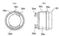
図3は、超音波センサ100の分解斜視図であり、図3(a)は、超音波振動子10を筒状弾性体33に被着する前の様子、図3(b)は、筒状弾性体33を被着した超音波振動子10をケース30に組み付ける様子を示している。また、図4は、筒状弾性体33の拡大図であり、図4(a)は、筒状弾性体33の底面図、図4(b)は、筒状弾性体33の側面図である。
3 is an exploded perspective view of the
筒状弾性体33はシリコンゴムからなり、超音波振動子10からケース30への不要振動の伝達を抑制するために、超音波振動子10の外周面(ハウジング11の筒部11c面)に被せられている。
The cylindrical
図3および図4に示されるように、筒状弾性体33は、ケース30の開口面32の開口端側に配置された突起状の係止部33aと、超音波振動子10の外周面を覆う外周面33bと、外周面33bの外面に設けられた第2の基準部33cと、筒状弾性体33のうちケース30の開口面32への挿入方向先端側に設けられた係止部33dと、外周面33bの内壁において第1の基準部14aに対応して設けられた切り欠き部33eとを備えた構成とされている。
As shown in FIGS. 3 and 4, the cylindrical
係止部33aと係止部33dは、超音波振動子10をケース30の開口面32に挿入した際に、挿入方向の先端位置と後端位置とで開口面32の壁面を挟持するためのものである。具体的には、係止部33dがガイド部31に設けられた位置決め用穴31aとは別の貫通孔(図示せず)を貫通して、ガイド部31の回路基板側面(裏面)に係止されるようになっており、係止部33aと共にケース30の開口面32の壁面を狭持するようになっている。
When the
外周面33bは、その内径が超音波振動子10の径と同等ないし若干小さくされており、超音波振動子10を収容したときに超音波振動子10に隙間なく被着できるような構造とされている。
The outer
第2の基準部33cは、ケース30の開口面32への挿入方向と平行に設けられ、超音波振動子10に筒状弾性体33を被着したときに、第1の基準部14aの先端位置と比べて、若干超音波振動子10の径方向への突出が小さくなる程度の高さとされている。
The
切り欠き部33eは、超音波振動子10に筒状弾性体33を被着する際に、第1の基準部14aが妨げにならないようにするために設けられている。
The
このような構成により、超音波振動子10の挿入方向において、第2の基準部33cに対して第1の基準部14aが同一直線上に配置されるように、超音波振動子10に筒状弾性体33を被着させると、この被着状態で、超音波振動子10の第1の基準部14aと筒状弾性体33の第2の基準部33cは、挿入方向において同一直線上となり、第1の基準部14aの突出先端は、筒状弾性体33の外周面33bから露出する。そして、ケース30に設けられた溝状の第3の基準部38に第1の基準部14aの突出先端をガイドさせた状態で、超音波振動子10を開口面32からケース30内に挿入することで、保護部18がガイド部31の位置決め用穴31aを貫通する。し、接続ピン15がインサートピン21の穴部21aに挿入される。また、筒状弾性体33の係止部33dがガイド部31に設けられた貫通孔31bを貫通し、両係止部33a、33dによりケース30に超音波振動子10が固定される。
With such a configuration, the
発泡弾性体34は、第1の弾性体に相当するもので、超音波振動子10のハウジング11内に配置された発泡弾性体19と同様、発泡ゴムやシリコン等からなり、接続ピン15及び保護部18が貫通配置されている。発泡弾性体34には切り込みが設けられ、その切り込み内に保護部18が挿入可能な構成としている。なお、超音波振動子10(ベース14)、筒状弾性体33、及び発泡弾性体34は、シリコン系接着剤により相互に接着固定されている。
The foamed
また、ガイド部31により区画されたケース30の回路基板20が配置される側には、防湿性部材35が充填されている。防湿性部材35としては、例えばシリコン樹脂やウレタン樹脂を適用することができる。本実施形態においてはシリコン樹脂を適用している。なお、図2(a)、(b)に示すように、回路基板20から外部に出力するための外部出力端子36が備えられ、ケース30の一面に形成されたコネクタ37から外部出力端子36の一端側が露出させられた構成とされている。
Further, a moisture-
次に、ケース30への超音波振動子10の組み付けの一例を示す。超音波振動子10に筒状弾性体33及び発泡弾性体34を配置した状態で、ケース30の開口面32から超音波振動子10を挿入する。このとき、保護部18(接続ピン15を含む)をケース30に設けたガイド部31の位置決め用穴31aに挿入する。そして、筒状弾性体33における係止部33dをケース30のガイド部31に設けられた貫通孔31b内に挿入させ、ガイド部31の裏面に係止させる。
Next, an example of assembling the
これにより、ケース30に対して超音波振動子10が所定の配置となり、接続ピン15がインサートピン21の穴部21aに挿入される。そして、筒状弾性体33の係止部33a、33dにより、筒状弾性体33に被着された超音波振動子10がケース30の開口面32に固定される。この状態でインサートピン21と接続ピン15とのはんだ付けが実施される。
As a result, the
さらに、回路基板20をケース30内に配置する。これにより、インサートピン21の端部21bが回路基板20のスルーホール20aに挿入されると共に、外部出力端子36の先端部36aも回路基板20のスルーホール(第1スルーホール)20bに挿入される。この状態ではんだ付けが実施され、インサートピン21を通じての圧電素子12と回路基板20との電気的接続や、外部出力端子36と回路基板20との電気的接続が為される。
Further, the
この後、ケース30の回路基板配置側の内部空間に防湿性部材35を充填する。なお、ここでは回路基板20を超音波振動子10が配置された後にケース30に配置したが、超音波振動子10の配置前に、ケース30に配置しておいても良い。
Thereafter, the moisture-
このように、本実施形態においては、接続ピン15がベース14の所定場所から突き出させた構造としてある。このため、位置決め用穴31aに保護部18を挿入することで、ケース30(インサートピン21)に対して超音波振動子10(接続ピン15)を位置決めすることができる。したがって、超音波振動子10および回路基板20をケース30に挿入しただけで、接続ピン15湾曲や折曲等を防止しつつ、接続ピン15のインサートピン21の穴部21aへの挿入や、インサートピン21の端部21bの回路基板20のスルーホール20aへの挿入が行える。これにより、超音波センサ100の組み付け作業性を向上させることが可能となる。
Thus, in this embodiment, it is set as the structure where the
以上説明した本実施形態の超音波センサ100によれば、接続ピン15が回路基板20に直接接続されるのではなく、インサートピン21を介して回路基板20に接続されるようにしている。このため、超音波振動子10が外部から押されることで接続ピン15が押し込まれても、そのとき発生する応力をインサートピン21にて吸収することが可能となる。このため、超音波振動子10が押し込まれたときに圧電素子12と回路基板20との電気的な接続が破壊されないようにできる。
According to the
また、インサートピン21の穴部21aの配置場所を接続ピン15の先端位置と一致させている。このため、超音波振動子10をケース30の開口面32に挿入すれば、接続ピン15がそのままインサートピン21の穴部21aに挿入される。これにより、超音波センサ100の組み付け作業性を向上させることが可能となる。
Further, the arrangement location of the
同様に、インサートピン21の端部21bや外部出力端子36の先端部36aを回路基板20のスルーホール20a、20bと一致させている。このため、ケース30に回路基板20を挿入すれば、インサートピン21の端部21bや外部出力端子36の先端部36aが回路基板20のスルーホール20a、20bに挿入される。これにより、超音波センサ100の組み付け作業性を向上させることが可能となる。
(他の実施形態)
以上本発明の好ましい実施形態について説明したが、本発明は上述の実施形態のみに限定されず、種々変更して実施することができる。
Similarly, the
(Other embodiments)
Although the preferred embodiments of the present invention have been described above, the present invention is not limited to the above-described embodiments, and can be implemented with various modifications.
例えば、中継ピンとなるインサートピン21をケース30に対してインサート成形することで一体化しているが、インサート成形でなくても良い。また、インサートピン21の形状も任意である。例えば、上記実施形態では、インサートピン21のうち少なくともケース30の中空部に露出している部分を薄肉とすることで、インサートピン21に応力が加えられたときに撓みやすくしているが、インサートピン21のうち少なくともケース30の中空部に露出している部分の一部を部分的に薄くした構造としても、上記と同様の効果を得ることができる。
For example, the
10…超音波振動子、11…ハウジング、11a…底部、12…圧電素子、14…ベース、14a…第1の基準部、15…接続ピン、20…回路基板、20a…スルーホール、20b…スルーホール、21…インサートピン、21a…穴部、21b…端部、30…ケース、31…ガイド部、31a…位置決め用穴、32…開口面、33…筒状弾性体、33a…係止部、33b…外周面、33c…第2の基準部、33d…係止部、34…発泡弾性体、36…外部出力端子、36a…先端部、37…コネクタ、38…第3の基準部、100…超音波センサ。
DESCRIPTION OF
Claims (7)
前記超音波振動子(10)の外周面および前記接続ピン(15)が引き出される側の面に被着された筒状弾性体(33)と、
開口面(32)を有し、前記筒状弾性体(33)が被着された状態で前記超音波振動子(10)が前記開口面(32)から挿入されることで、前記開口面(32)の内部に組み付けられる中空状のケース(30)と、
前記ケース(30)における中空部に露出するように設けられ、該露出した部分が前記接続ピン(15)に電気的に接続されると共に、前記接続ピン(15)が前記超音波振動子(10)を前記開口面(32)に挿入する方向に押し込まれると、該方向に撓む中継ピン(21)と、
前記ケース(30)の前記中空部内に配置され、前記中継ピン(21)に電気的に接続されることで、該中継ピン(21)および前記接続ピン(15)を介して前記圧電素子(12)と電気的に接続された回路基板(20)と、を備えている超音波センサ。 A bottomed cylindrical housing (11), a piezoelectric element (12) fixed to the inner surface of the bottom (11a) of the housing (11), and the piezoelectric element (12) are electrically connected, and one end is A connection pin (15) drawn to the outside of the housing (11), a base (14) made of an insulating material and fixed to the housing (11) in a state where the connection pin (15) is disposed through; An ultrasonic transducer (10) constituted by:
A cylindrical elastic body (33) attached to the outer peripheral surface of the ultrasonic transducer (10) and the surface from which the connection pin (15) is drawn;
The ultrasonic transducer (10) is inserted from the opening surface (32) with the opening elastic surface (32) and the cylindrical elastic body (33) attached thereto, whereby the opening surface ( 32) a hollow case (30) assembled inside,
The case (30) is provided so as to be exposed in a hollow portion, the exposed portion is electrically connected to the connection pin (15), and the connection pin (15) is connected to the ultrasonic transducer (10). ) Is pushed in the direction of insertion into the opening surface (32), the relay pin (21) bends in that direction;
The piezoelectric element (12) is disposed in the hollow portion of the case (30) and electrically connected to the relay pin (21) via the relay pin (21) and the connection pin (15). And a circuit board (20) electrically connected to the ultrasonic sensor.
前記接続ピン(15)のうち前記ハウジング(11)の外部に引き出された一端を前記位置決め用穴(31a)に挿入すると、前記インサートピン(21)の前記穴部(21a)に挿入されるように構成されていることを特徴とする請求項3に記載の超音波センサ。 The opening (32) where the ultrasonic transducer (10) is arranged in the case (30) and the hollow part where the circuit board (20) is arranged are partitioned, and the connection pin (15) is A guide portion (31) in which a positioning hole (31a) to be inserted is formed;
When one end of the connection pin (15) drawn out of the housing (11) is inserted into the positioning hole (31a), it is inserted into the hole (21a) of the insert pin (21). The ultrasonic sensor according to claim 3, wherein the ultrasonic sensor is configured as follows.
前記筒状弾性体(33)の外周面(33b)に形成された第2の基準部(33c)と、
前記ケース(30)における前記開口面(32)の内壁に形成された第3の基準部(38)と、を有し、
前記第1の基準部(14a)と前記第2の基準部(33c)とを位置合わせして前記筒状弾性体(33)を前記超音波振動子(10)に被着した状態で、前記第1、第2の基準部(14a、33c)と前記第3の基準部(38)とを位置合わせして前記超音波振動子(10)を前記開口面(32)に挿入するように構成されていることを特徴とする請求項3または4に記載の超音波センサ。 A first reference portion (14a) provided in the ultrasonic transducer (10) and projecting in a radial direction of the ultrasonic transducer (10) from an outer peripheral surface of the ultrasonic transducer (10);
A second reference portion (33c) formed on the outer peripheral surface (33b) of the cylindrical elastic body (33);
A third reference portion (38) formed on the inner wall of the opening surface (32) in the case (30),
In a state where the first reference portion (14a) and the second reference portion (33c) are aligned and the cylindrical elastic body (33) is attached to the ultrasonic transducer (10), The first and second reference portions (14a, 33c) and the third reference portion (38) are aligned, and the ultrasonic transducer (10) is inserted into the opening surface (32). The ultrasonic sensor according to claim 3, wherein the ultrasonic sensor is provided.
該外部出力端子(36)のうち前記回路基板(20)に接続される一端(36a)が前記回路基板(20)を前記ケース(30)の前記中空部に挿入する方向と平行に引き出されており、前記回路基板(20)を前記ケース(30)の前記中空部に挿入したときに、外部出力端子(36)の一端(36a)が前記回路基板(20)に備えられた第2スルーホール(20b)に挿入されるように、前記外部出力端子(36)の一端(36a)および前記回路基板(20)に備えられた前記第2スルーホール(20b)の位置が設定されていることを特徴とする請求項6に記載の超音波センサ。
The case (30) includes an external output terminal (36) that is electrically connected to the circuit board (20) by being inserted into the second through hole (20b) of the circuit board (20). ,
One end (36a) of the external output terminal (36) connected to the circuit board (20) is pulled out in parallel with the direction in which the circuit board (20) is inserted into the hollow portion of the case (30). When the circuit board (20) is inserted into the hollow part of the case (30), one end (36a) of the external output terminal (36) is provided in the circuit board (20). The position of one end (36a) of the external output terminal (36) and the second through hole (20b) provided in the circuit board (20) is set so as to be inserted into (20b). The ultrasonic sensor according to claim 6.
Priority Applications (4)
| Application Number | Priority Date | Filing Date | Title |
|---|---|---|---|
| JP2006107291A JP4720587B2 (en) | 2006-04-10 | 2006-04-10 | Ultrasonic sensor |
| US11/727,454 US7317663B2 (en) | 2006-04-10 | 2007-03-27 | Ultrasonic sensor |
| DE102007016068A DE102007016068B4 (en) | 2006-04-10 | 2007-04-03 | ultrasonic sensor |
| CN200710096035A CN100575985C (en) | 2006-04-10 | 2007-04-10 | ultrasonic sensor |
Applications Claiming Priority (1)
| Application Number | Priority Date | Filing Date | Title |
|---|---|---|---|
| JP2006107291A JP4720587B2 (en) | 2006-04-10 | 2006-04-10 | Ultrasonic sensor |
Publications (2)
| Publication Number | Publication Date |
|---|---|
| JP2007281999A JP2007281999A (en) | 2007-10-25 |
| JP4720587B2 true JP4720587B2 (en) | 2011-07-13 |
Family
ID=38514844
Family Applications (1)
| Application Number | Title | Priority Date | Filing Date |
|---|---|---|---|
| JP2006107291A Expired - Lifetime JP4720587B2 (en) | 2006-04-10 | 2006-04-10 | Ultrasonic sensor |
Country Status (4)
| Country | Link |
|---|---|
| US (1) | US7317663B2 (en) |
| JP (1) | JP4720587B2 (en) |
| CN (1) | CN100575985C (en) |
| DE (1) | DE102007016068B4 (en) |
Families Citing this family (28)
| Publication number | Priority date | Publication date | Assignee | Title |
|---|---|---|---|---|
| CN101297591B (en) * | 2005-12-14 | 2011-09-07 | 株式会社村田制作所 | Ultrasonic transducer |
| JP4893322B2 (en) * | 2006-03-23 | 2012-03-07 | 株式会社デンソー | Ultrasonic sensor |
| JP4609537B2 (en) * | 2008-06-20 | 2011-01-12 | パナソニック電工株式会社 | Ultrasonic sensor |
| JP5386910B2 (en) * | 2008-09-26 | 2014-01-15 | 株式会社デンソー | Electronic circuit equipment |
| JP5075171B2 (en) * | 2009-09-02 | 2012-11-14 | パナソニック株式会社 | Ultrasonic sensor |
| JP5304578B2 (en) * | 2009-09-30 | 2013-10-02 | 株式会社村田製作所 | Ultrasonic transducer |
| JP5728657B2 (en) * | 2009-10-01 | 2015-06-03 | パナソニックIpマネジメント株式会社 | Ultrasonic flow measurement unit |
| JP2011239089A (en) * | 2010-05-07 | 2011-11-24 | Denso Corp | Ultrasonic sensor, adjustment method, and manufacturing method thereof |
| JP5607990B2 (en) * | 2010-05-14 | 2014-10-15 | パナソニック株式会社 | Ultrasonic sensor |
| DE102010026341A1 (en) * | 2010-07-07 | 2012-01-12 | Giesecke & Devrient Gmbh | Ultrasonic sensor for value documents, converter module for this and method for producing the ultrasonic sensor |
| CN102129070B (en) * | 2010-12-04 | 2013-03-20 | 广州市番禺奥迪威电子有限公司 | Vehicle-mounted ultrasonic wave sensor |
| JP2012198106A (en) * | 2011-03-22 | 2012-10-18 | Panasonic Corp | Ultrasonic sensor |
| CN202075408U (en) * | 2011-04-22 | 2011-12-14 | 博世汽车部件(苏州)有限公司 | Ultrasonic transducer, sensor and reverse radar system |
| JP5814798B2 (en) * | 2012-01-06 | 2015-11-17 | 日本セラミック株式会社 | Ultrasonic transducer |
| CN103292893B (en) * | 2013-05-17 | 2016-08-10 | 广东奥迪威传感科技股份有限公司 | A kind of ultrasonic sensor |
| KR102131449B1 (en) * | 2013-06-26 | 2020-08-05 | 현대모비스 주식회사 | Ultrasonic sensor assembly and manufacturing method |
| JP2015087219A (en) * | 2013-10-30 | 2015-05-07 | 同致電子企業股▲ふん▼有限公司 | Back sensor |
| CN103612604A (en) * | 2013-11-04 | 2014-03-05 | 法雷奥汽车内部控制(深圳)有限公司 | High-degree-sealing waterproof type reversing radar |
| CN104678377A (en) * | 2013-11-27 | 2015-06-03 | 法雷奥汽车内部控制(深圳)有限公司 | Ultrasonic sensor and manufacturing method thereof |
| CN103675798A (en) * | 2013-12-02 | 2014-03-26 | 法雷奥汽车内部控制(深圳)有限公司 | Sealed and waterproof ultrasonic probe |
| CN105093228A (en) * | 2014-05-08 | 2015-11-25 | 光宝科技股份有限公司 | Ultrasonic Sensing Module |
| CN108024784A (en) * | 2015-07-20 | 2018-05-11 | Cvr 环球股份有限公司 | For detecting sensor, transducer gasket and the sensor array of infrasonic sound acoustic signal |
| JP6759615B2 (en) * | 2016-02-12 | 2020-09-23 | 株式会社ジェイテクト | Circuit board assembly, insert-molded products, and manufacturing methods for insert-molded products |
| CN107797114A (en) * | 2016-09-02 | 2018-03-13 | 法雷奥汽车内部控制(深圳)有限公司 | A kind of ultrasonic sensor for motor vehicle |
| CN106287240B (en) * | 2016-09-05 | 2018-10-30 | 中国石油大学(华东) | A kind of pipeline leakage testing device and single-sensor localization method based on sound emission |
| DE102017214373A1 (en) * | 2017-08-17 | 2019-02-21 | Landis + Gyr Gmbh | Transducer for a flowmeter with extraction means |
| JP7192640B2 (en) * | 2019-04-23 | 2022-12-20 | 株式会社Soken | ultrasonic sensor |
| JP7418007B2 (en) * | 2020-05-25 | 2024-01-19 | パナソニックIpマネジメント株式会社 | Piezoelectric element connection structure, vehicle, and piezoelectric element connection method |
Family Cites Families (14)
| Publication number | Priority date | Publication date | Assignee | Title |
|---|---|---|---|---|
| US3964296A (en) * | 1975-06-03 | 1976-06-22 | Terrance Matzuk | Integrated ultrasonic scanning apparatus |
| JPH0562884A (en) | 1991-08-30 | 1993-03-12 | Fujitsu Ltd | X-ray exposure device |
| JP3379073B2 (en) | 1994-06-17 | 2003-02-17 | 本田技研工業株式会社 | Ultrasonic transducer |
| JPH08130795A (en) | 1994-11-02 | 1996-05-21 | Matsushita Electric Ind Co Ltd | Ultrasonic sensor |
| JP3628480B2 (en) | 1997-05-30 | 2005-03-09 | 株式会社デンソー | Ultrasonic sensor |
| DE69733471D1 (en) * | 1997-07-03 | 2005-07-14 | St Microelectronics Srl | Method of manufacturing devices in a semiconductive substrate |
| JP3726465B2 (en) | 1997-12-24 | 2005-12-14 | 株式会社村田製作所 | Ultrasonic transducer |
| JP3879264B2 (en) | 1998-07-01 | 2007-02-07 | 株式会社村田製作所 | Ultrasonic sensor |
| JP2002055156A (en) * | 2000-08-11 | 2002-02-20 | Nippon Soken Inc | Ultrasonic sensor |
| JP2002199481A (en) | 2000-12-25 | 2002-07-12 | Denso Corp | VEHICLE ULTRASONIC DETECTOR AND ITS MANUFACTURING METHOD |
| JP4251790B2 (en) * | 2001-06-19 | 2009-04-08 | 三菱電機株式会社 | Ultrasonic obstacle detection device and assembly method thereof |
| JP2003079621A (en) * | 2001-09-14 | 2003-03-18 | Toshiba Corp | Ultrasonic probe and ultrasonic diagnostic device |
| JP3651475B2 (en) * | 2003-12-03 | 2005-05-25 | 株式会社デンソー | Ultrasonic sensor and ultrasonic transducer used for the ultrasonic sensor |
| JP4438667B2 (en) * | 2005-03-29 | 2010-03-24 | 株式会社デンソー | Ultrasonic sensor and ultrasonic transducer |
-
2006
- 2006-04-10 JP JP2006107291A patent/JP4720587B2/en not_active Expired - Lifetime
-
2007
- 2007-03-27 US US11/727,454 patent/US7317663B2/en active Active
- 2007-04-03 DE DE102007016068A patent/DE102007016068B4/en active Active
- 2007-04-10 CN CN200710096035A patent/CN100575985C/en active Active
Also Published As
| Publication number | Publication date |
|---|---|
| CN100575985C (en) | 2009-12-30 |
| US20070237031A1 (en) | 2007-10-11 |
| US7317663B2 (en) | 2008-01-08 |
| DE102007016068A1 (en) | 2007-10-18 |
| JP2007281999A (en) | 2007-10-25 |
| DE102007016068B4 (en) | 2013-01-24 |
| CN101055313A (en) | 2007-10-17 |
Similar Documents
| Publication | Publication Date | Title |
|---|---|---|
| JP4720587B2 (en) | Ultrasonic sensor | |
| JP4893322B2 (en) | Ultrasonic sensor | |
| CN101038339B (en) | Ultrasonic sensor | |
| JP4438667B2 (en) | Ultrasonic sensor and ultrasonic transducer | |
| CN108431627B (en) | Ultrasonic sensor | |
| JP4742923B2 (en) | Ultrasonic sensor | |
| CN110431445B (en) | Ultrasonic sensor | |
| CN102726064B (en) | Ultrasonic vibration device | |
| WO2007029506A1 (en) | Ultrasonic sensor | |
| CN104246533B (en) | Ultrasonic sensor device for vehicle and method of assembling ultrasonic sensor device for vehicle | |
| JP5195572B2 (en) | Ultrasonic sensor | |
| JP2009214610A (en) | Mounting structure of ultrasonic sensor | |
| JP2009227085A (en) | Mounting structure of ultrasonic sensor | |
| CN107367732B (en) | Ultrasonic sensor | |
| JP2006337028A (en) | Ultrasonic sensor device and ultrasonic sensor mounting method | |
| JP5673217B2 (en) | Ultrasonic sensor | |
| JP4640223B2 (en) | Ultrasonic sensor | |
| WO2018164153A1 (en) | Ultrasonic sensor | |
| CN209344167U (en) | Vehicle-mounted device | |
| JP2013024846A (en) | Ultrasonic sensor | |
| JP2011053561A (en) | Siren | |
| CN110891224B (en) | Waterproof loudspeaker | |
| JP2023178719A (en) | ultrasonic transducer |
Legal Events
| Date | Code | Title | Description |
|---|---|---|---|
| A621 | Written request for application examination |
Free format text: JAPANESE INTERMEDIATE CODE: A621 Effective date: 20090318 |
|
| A977 | Report on retrieval |
Free format text: JAPANESE INTERMEDIATE CODE: A971007 Effective date: 20110228 |
|
| TRDD | Decision of grant or rejection written | ||
| A01 | Written decision to grant a patent or to grant a registration (utility model) |
Free format text: JAPANESE INTERMEDIATE CODE: A01 Effective date: 20110308 |
|
| A61 | First payment of annual fees (during grant procedure) |
Free format text: JAPANESE INTERMEDIATE CODE: A61 Effective date: 20110321 |
|
| FPAY | Renewal fee payment (event date is renewal date of database) |
Free format text: PAYMENT UNTIL: 20140415 Year of fee payment: 3 |
|
| R151 | Written notification of patent or utility model registration |
Ref document number: 4720587 Country of ref document: JP Free format text: JAPANESE INTERMEDIATE CODE: R151 |
|
| FPAY | Renewal fee payment (event date is renewal date of database) |
Free format text: PAYMENT UNTIL: 20140415 Year of fee payment: 3 |
|
| R250 | Receipt of annual fees |
Free format text: JAPANESE INTERMEDIATE CODE: R250 |
|
| R250 | Receipt of annual fees |
Free format text: JAPANESE INTERMEDIATE CODE: R250 |
|
| R250 | Receipt of annual fees |
Free format text: JAPANESE INTERMEDIATE CODE: R250 |
|
| R250 | Receipt of annual fees |
Free format text: JAPANESE INTERMEDIATE CODE: R250 |
|
| R250 | Receipt of annual fees |
Free format text: JAPANESE INTERMEDIATE CODE: R250 |
|
| R250 | Receipt of annual fees |
Free format text: JAPANESE INTERMEDIATE CODE: R250 |
|
| R250 | Receipt of annual fees |
Free format text: JAPANESE INTERMEDIATE CODE: R250 |
|
| R250 | Receipt of annual fees |
Free format text: JAPANESE INTERMEDIATE CODE: R250 |
|
| R250 | Receipt of annual fees |
Free format text: JAPANESE INTERMEDIATE CODE: R250 |
|
| R250 | Receipt of annual fees |
Free format text: JAPANESE INTERMEDIATE CODE: R250 |
|
| R250 | Receipt of annual fees |
Free format text: JAPANESE INTERMEDIATE CODE: R250 |
|
| R250 | Receipt of annual fees |
Free format text: JAPANESE INTERMEDIATE CODE: R250 |