JP4722012B2 - Compressed air system and compressed air unit - Google Patents
Compressed air system and compressed air unit Download PDFInfo
- Publication number
- JP4722012B2 JP4722012B2 JP2006297277A JP2006297277A JP4722012B2 JP 4722012 B2 JP4722012 B2 JP 4722012B2 JP 2006297277 A JP2006297277 A JP 2006297277A JP 2006297277 A JP2006297277 A JP 2006297277A JP 4722012 B2 JP4722012 B2 JP 4722012B2
- Authority
- JP
- Japan
- Prior art keywords
- outlet
- housing
- inlet
- compressed air
- heating
- Prior art date
- Legal status (The legal status is an assumption and is not a legal conclusion. Google has not performed a legal analysis and makes no representation as to the accuracy of the status listed.)
- Expired - Fee Related
Links
Images
Classifications
-
- F—MECHANICAL ENGINEERING; LIGHTING; HEATING; WEAPONS; BLASTING
- F04—POSITIVE - DISPLACEMENT MACHINES FOR LIQUIDS; PUMPS FOR LIQUIDS OR ELASTIC FLUIDS
- F04D—NON-POSITIVE-DISPLACEMENT PUMPS
- F04D29/00—Details, component parts, or accessories
- F04D29/58—Cooling; Heating; Diminishing heat transfer
- F04D29/582—Cooling; Heating; Diminishing heat transfer specially adapted for elastic fluid pumps
- F04D29/584—Cooling; Heating; Diminishing heat transfer specially adapted for elastic fluid pumps cooling or heating the machine
-
- B—PERFORMING OPERATIONS; TRANSPORTING
- B64—AIRCRAFT; AVIATION; COSMONAUTICS
- B64D—EQUIPMENT FOR FITTING IN OR TO AIRCRAFT; FLIGHT SUITS; PARACHUTES; ARRANGEMENT OR MOUNTING OF POWER PLANTS OR PROPULSION TRANSMISSIONS IN AIRCRAFT
- B64D13/00—Arrangements or adaptations of air-treatment apparatus for aircraft crew or passengers, or freight space
- B64D13/02—Arrangements or adaptations of air-treatment apparatus for aircraft crew or passengers, or freight space the air being pressurised
-
- B—PERFORMING OPERATIONS; TRANSPORTING
- B64—AIRCRAFT; AVIATION; COSMONAUTICS
- B64D—EQUIPMENT FOR FITTING IN OR TO AIRCRAFT; FLIGHT SUITS; PARACHUTES; ARRANGEMENT OR MOUNTING OF POWER PLANTS OR PROPULSION TRANSMISSIONS IN AIRCRAFT
- B64D13/00—Arrangements or adaptations of air-treatment apparatus for aircraft crew or passengers, or freight space
- B64D13/06—Arrangements or adaptations of air-treatment apparatus for aircraft crew or passengers, or freight space the air being conditioned
-
- F—MECHANICAL ENGINEERING; LIGHTING; HEATING; WEAPONS; BLASTING
- F04—POSITIVE - DISPLACEMENT MACHINES FOR LIQUIDS; PUMPS FOR LIQUIDS OR ELASTIC FLUIDS
- F04D—NON-POSITIVE-DISPLACEMENT PUMPS
- F04D25/00—Pumping installations or systems
- F04D25/02—Units comprising pumps and their driving means
- F04D25/06—Units comprising pumps and their driving means the pump being electrically driven
-
- F—MECHANICAL ENGINEERING; LIGHTING; HEATING; WEAPONS; BLASTING
- F04—POSITIVE - DISPLACEMENT MACHINES FOR LIQUIDS; PUMPS FOR LIQUIDS OR ELASTIC FLUIDS
- F04D—NON-POSITIVE-DISPLACEMENT PUMPS
- F04D27/00—Control, e.g. regulation, of pumps, pumping installations or pumping systems specially adapted for elastic fluids
- F04D27/02—Surge control
- F04D27/0207—Surge control by bleeding, bypassing or recycling fluids
- F04D27/0238—Details or means for fluid reinjection
-
- F—MECHANICAL ENGINEERING; LIGHTING; HEATING; WEAPONS; BLASTING
- F04—POSITIVE - DISPLACEMENT MACHINES FOR LIQUIDS; PUMPS FOR LIQUIDS OR ELASTIC FLUIDS
- F04D—NON-POSITIVE-DISPLACEMENT PUMPS
- F04D29/00—Details, component parts, or accessories
- F04D29/40—Casings; Connections of working fluid
- F04D29/42—Casings; Connections of working fluid for radial or helico-centrifugal pumps
- F04D29/4206—Casings; Connections of working fluid for radial or helico-centrifugal pumps especially adapted for elastic fluid pumps
- F04D29/4213—Casings; Connections of working fluid for radial or helico-centrifugal pumps especially adapted for elastic fluid pumps suction ports
-
- F—MECHANICAL ENGINEERING; LIGHTING; HEATING; WEAPONS; BLASTING
- F04—POSITIVE - DISPLACEMENT MACHINES FOR LIQUIDS; PUMPS FOR LIQUIDS OR ELASTIC FLUIDS
- F04D—NON-POSITIVE-DISPLACEMENT PUMPS
- F04D29/00—Details, component parts, or accessories
- F04D29/58—Cooling; Heating; Diminishing heat transfer
- F04D29/5806—Cooling the drive system
-
- B—PERFORMING OPERATIONS; TRANSPORTING
- B64—AIRCRAFT; AVIATION; COSMONAUTICS
- B64D—EQUIPMENT FOR FITTING IN OR TO AIRCRAFT; FLIGHT SUITS; PARACHUTES; ARRANGEMENT OR MOUNTING OF POWER PLANTS OR PROPULSION TRANSMISSIONS IN AIRCRAFT
- B64D13/00—Arrangements or adaptations of air-treatment apparatus for aircraft crew or passengers, or freight space
- B64D13/06—Arrangements or adaptations of air-treatment apparatus for aircraft crew or passengers, or freight space the air being conditioned
- B64D2013/0603—Environmental Control Systems
- B64D2013/0607—Environmental Control Systems providing hot air or liquid for deicing aircraft parts, e.g. aerodynamic surfaces or windows
-
- B—PERFORMING OPERATIONS; TRANSPORTING
- B64—AIRCRAFT; AVIATION; COSMONAUTICS
- B64D—EQUIPMENT FOR FITTING IN OR TO AIRCRAFT; FLIGHT SUITS; PARACHUTES; ARRANGEMENT OR MOUNTING OF POWER PLANTS OR PROPULSION TRANSMISSIONS IN AIRCRAFT
- B64D13/00—Arrangements or adaptations of air-treatment apparatus for aircraft crew or passengers, or freight space
- B64D13/06—Arrangements or adaptations of air-treatment apparatus for aircraft crew or passengers, or freight space the air being conditioned
- B64D2013/0603—Environmental Control Systems
- B64D2013/0644—Environmental Control Systems including electric motors or generators
-
- Y—GENERAL TAGGING OF NEW TECHNOLOGICAL DEVELOPMENTS; GENERAL TAGGING OF CROSS-SECTIONAL TECHNOLOGIES SPANNING OVER SEVERAL SECTIONS OF THE IPC; TECHNICAL SUBJECTS COVERED BY FORMER USPC CROSS-REFERENCE ART COLLECTIONS [XRACs] AND DIGESTS
- Y02—TECHNOLOGIES OR APPLICATIONS FOR MITIGATION OR ADAPTATION AGAINST CLIMATE CHANGE
- Y02T—CLIMATE CHANGE MITIGATION TECHNOLOGIES RELATED TO TRANSPORTATION
- Y02T50/00—Aeronautics or air transport
- Y02T50/50—On board measures aiming to increase energy efficiency
Landscapes
- Engineering & Computer Science (AREA)
- Mechanical Engineering (AREA)
- General Engineering & Computer Science (AREA)
- General Health & Medical Sciences (AREA)
- Health & Medical Sciences (AREA)
- Pulmonology (AREA)
- Aviation & Aerospace Engineering (AREA)
- Physics & Mathematics (AREA)
- Thermal Sciences (AREA)
- Sustainable Development (AREA)
- Life Sciences & Earth Sciences (AREA)
- Control Of Positive-Displacement Air Blowers (AREA)
- Structures Of Non-Positive Displacement Pumps (AREA)
Description
本発明は、例えば飛行機において圧縮空気を客室用空調システムに供給するように用いられるコンプレッサに関する。 The present invention relates to a compressor used for supplying compressed air to a cabin air conditioning system, for example, in an airplane.
飛行機におけるあるコンプレッサ応用例では、コンプレッサインレットに入る空気が水分を含み、かつ氷点下で運転する。インレットに形成される氷がコンプレッサの熱力学的性能を低下させ、氷が脱落するに従いコンプレッサを破損する可能性があり、コンプレッサのベアリングや支持構造を破損させる可能性がある。 In some compressor applications in airplanes, the air entering the compressor inlet contains moisture and operates below freezing. Ice formed in the inlet can reduce the thermodynamic performance of the compressor and can damage the compressor as the ice falls off, possibly damaging the compressor bearings and support structure.
コンプレッサは時としてコンプレッサアウトレット圧力とコンプレッサインレット圧力との比率が望ましくない、不都合なサージ条件で運転することがある。サージを回避するため、所望の範囲内の圧力比を得るようにコンプレッサアウトレット圧力を低下させる、もしくはコンプレッサインレット圧力を増加させることが望ましい。 Compressors sometimes operate in adverse surge conditions where the ratio of compressor outlet pressure to compressor inlet pressure is undesirable. In order to avoid surges, it is desirable to reduce the compressor outlet pressure or increase the compressor inlet pressure to obtain a pressure ratio in the desired range.
効率よく急速にコンプレッサインレットを除氷しサージを制御することが可能な、除氷およびサージ制御装置が必要である。 There is a need for a deicing and surge control device that is capable of efficiently and quickly deicing a compressor inlet and controlling surge.
本発明はインレットとアウトレットとをもつコンプレッサを含んでなる圧縮空気システムを提供する。流体が流れるようにアウトレットをインレットにダクトでつなぐとともに、このダクトに配置された弁をもつ。コントローラが弁と接続され、サージ条件や加熱条件に対応して第1の位置と第2の位置との間を移動するようにこの弁に指令してダクトを通流する流体の量を調節する。インレットを除氷するようにコンプレッサアウトレットから高温空気を供給するため、もしくは所望の範囲の圧力比を得るように高圧力のコンプレッサアウトレット空気を低圧力のコンプレッサインレット空気に供給するため、弁が開く。 The present invention provides a compressed air system comprising a compressor having an inlet and an outlet. The outlet is ducted to the inlet for fluid flow and has a valve disposed in the duct. A controller is connected to the valve and commands the valve to move between the first and second positions in response to surge and heating conditions to adjust the amount of fluid flowing through the duct. . The valve opens to supply hot air from the compressor outlet to deicing the inlet, or to supply high pressure compressor outlet air to low pressure compressor inlet air to obtain a desired range of pressure ratios.
本発明の圧縮空気ユニットは、インレットに加熱、加圧空気を供給する弁が素早く応答するようにインレットのすぐそばに配置された、コンパクトな配置を提供するように設計されている。ダクトは、コンプレッサのハウジングに備えられた加熱供給アウトレットと加熱プレナムインレットとを相互接続する相対的に短い配管材料を備える。またハウジングは環状キャビティを提供するようにインレットに配置された環状壁をもつ加熱プレナムを含む。コンプレッサアウトレットからの高温空気がプレナムに供給されて着氷を防ぐようにインレットで急速に環状壁を加熱する。 The compressed air unit of the present invention is designed to provide a compact arrangement that is placed right next to the inlet so that the valve that supplies the heated and pressurized air to the inlet responds quickly. The duct comprises a relatively short piping material that interconnects the heating supply outlet and the heating plenum inlet provided in the compressor housing. The housing also includes a heated plenum having an annular wall disposed in the inlet to provide an annular cavity. Hot air from the compressor outlet is supplied to the plenum to rapidly heat the annular wall at the inlet to prevent icing.
したがって、本発明はコンプレッサを除氷しサージを防ぐ、除氷およびサージ制御装置を提供する。 Accordingly, the present invention provides a deicing and surge control device that deicers a compressor to prevent surges.
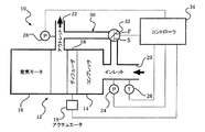
圧縮空気システムを図1の符号10で示す。圧縮空気システム10は電気モータ16によって駆動されるコンプレッサ14を備えた圧縮空気ユニット12を含む。周知のようにディフューザ18はコンプレッサ14のアウトレット22の前に配置される。ディフューザ18はその領域を変化させるアクチュエータ19によって制御される。空気はインレット20を通してコンプレッサ14に入る。インレット圧力センサ24およびインレット温度センサ26がインレット20に配置され、アウトレット圧力センサ28がアウトレット22に配置される。アクチュエータ19、センサ24,26,28がコントローラ34と接続するように模式的に示されている。コントローラ34はセンサ24,26,28を用いてサージ条件および加熱条件を測定する。上記の圧縮空気システム10は、例えば圧縮空気を、客室用調和空気(客室用空調)をつくり出す空気循環装置に供給するのに適している。
A compressed air system is shown at 10 in FIG. The
本発明はインレット20とアウトレット22とを流体が流れるように連結したダクト30を利用する。弁32がダクト30内のインレット20とアウトレット22との間に配置される。サージ条件および加熱条件に対応してこの弁が第1の位置Fと第2の位置Sとの間を移動するようにコントローラ34が弁32に接続される。本発明により、これらの条件に対して一つの弁しか使用されない。一実施例では、弁32はバタフライバルブである。
The present invention utilizes a
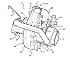
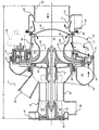
図2および図3を参照すると、ワイヤ38がハウジング40から延びて電気モータ16に電力を供給している。ハウジング40は、互いに留め具49によって固定された、モータハウジング部42、アウトレットハウジング部44、加熱ハウジング部46およびインレットハウジング部48を含んでなる。スクリーン50は加熱ハウジング部46とインレットハウジング部48との間に配置される。冷却供給プレナム52がインレット20に配置されて電気モータ16に冷却空気を供給する。冷却供給プレナム52は、一部、第1のフランジ51および第2のフランジ53によって画定される。冷却供給プレナム52は、ベアリング冷却ダクト36によって冷却インレット56に連結されたアウトレット54を含む(図2に示す)。ベアリング62は電気モータ16のロータ64を支持する。ベアリング冷却インレット58はダクトを介してベアリング冷却アウトレット60に冷却空気を供給する(図示せず)。
With reference to FIGS. 2 and 3, a
インペラ66がロータ64に固定されている。インペラ66はインレット側65およびアウトレット側67をもつ。ディフューザ18はインペラ66とアウトレット22との間のアウトレット側67に配置される。ハウジング40はインペラ66のすぐそばにディフューザシュラウド68を含む。ディフューザシュラウド68はインペラ66の端部69を越えるように延びる。
An
ハウジング40はディフューザシュラウド68と加熱ハウジング部46とによって形成される加熱プレナム72を提供する。ディフューザシュラウド68は、インペラ66の端部69から軸方向に延びるに従い半径方向外側へ向かうテーパ状をなす曲線状の環状壁70を提供する。
The
アウトレットハウジング44は、加熱ハウジング部46の加熱プレナムインレット76に連結された加熱供給アウトレット74(図2に最もよく示す)を提供する。例に示すように、ダクト30は圧縮空気ユニット12の長さL1に比べて短い長さL2(破線により示す)をもち、相対的に短い。この相対的に短い長さにより、曲線状の環状壁70は加熱条件の感知に応答して素早く加熱される。同様に、サージ条件を感知したときの応答時間は素早い。離れたところに位置する弁は望ましい応答時間を提供しない。
22…アウトレット
30…ダクト
40…ハウジング
46…加熱ハウジング部
66…インペラ
68…ディフューザシュラウド
70…環状壁
72…加熱プレナム
DESCRIPTION OF
Claims (13)
インレットとアウトレットとをもつコンプレッサと、
前記アウトレットを前記インレットに連結するとともに、弁が配置されたダクトと、
前記弁と接続されるとともに、サージ条件および加熱条件に対応して第1の位置と第2の位置との間を移動するように指令して前記ダクトを通流する流体の量を調節するコントローラと、
を備え、
前記コンプレッサが、概ね環状の壁をもつ加熱プレナムを提供するハウジングを含むとともに、前記加熱プレナムを前記アウトレットに前記ダクトで連結し、
前記ハウジングが、前記コンプレッサのインペラを少なくとも部分的に取り囲むシュラウドを含み、このシュラウドが前記の概ね環状の壁を提供し、
前記弁が、前記加熱条件に対応して前記第1の位置から前記第2の位置へと移動して、前記環状壁を加熱するように前記アウトレットから前記加熱プレナムに流体を供給することを特徴とする圧縮空気システム。 A compressed air system for an aircraft cabin air conditioning system,
A compressor having an inlet and an outlet;
A duct connecting the outlet to the inlet and having a valve disposed thereon;
A controller connected to the valve and controlling the amount of fluid flowing through the duct by commanding movement between a first position and a second position in response to surge and heating conditions When,
With
The compressor includes a housing that provides a heated plenum having a generally annular wall, and connects the heated plenum to the outlet with the duct;
The housing includes a shroud that at least partially surrounds the impeller of the compressor, the shroud providing the generally annular wall;
The valve moves from the first position to the second position in response to the heating condition to supply fluid from the outlet to the heating plenum to heat the annular wall. And compressed air system.
インレットとアウトレットの各々を提供する第1のハウジング部と第2のハウジング部とを含むとともに、この第1のハウジング部および第2のハウジング部が、各々、前記インレットおよび前記アウトレットに連通する加熱プレナムインレットおよび加熱供給アウトレットを提供するハウジングと、
前記ハウジングの前記インレットと前記アウトレットとの間に配置された流体を圧縮するインペラと、
前記加熱供給アウトレットと前記加熱プレナムインレットとを連結するとともに、前記アウトレットから前記インレットへの流体の流れを調整するように配置された弁をもつダクトと、
を備え、
加熱プレナムを加熱するように前記加熱供給アウトレットから前記加熱プレナムインレットに高温空気の一部を供給することを特徴とする圧縮空気ユニット。 A compressed air unit,
A heating plenum including a first housing portion and a second housing portion for providing each of an inlet and an outlet, wherein the first housing portion and the second housing portion communicate with the inlet and the outlet, respectively. A housing providing an inlet and a heating supply outlet;
An impeller for compressing a fluid disposed between the inlet and the outlet of the housing;
A duct having a valve connecting the heated supply outlet and the heated plenum inlet and arranged to regulate a flow of fluid from the outlet to the inlet;
Equipped with a,
A compressed air unit, wherein a portion of hot air is supplied from the heating supply outlet to the heating plenum inlet to heat the heating plenum .
インレットとアウトレットとを含むハウジングと、
前記インレットと前記アウトレットとの間に配置されたインペラと、
環状キャビティを画定する環状壁を含んでなるプレナムを提供するとともに、前記環状キャビティが前記インレットおよび前記アウトレットと連通し、かつ前記環状壁が前記インペラに隣接するハウジングの一部と、
を備え、
前記環状壁を加熱するように前記アウトレットから前記プレナムに高温空気の一部を供給することを特徴とする圧縮空気ユニット。 A compressed air unit,
A housing including an inlet and an outlet;
An impeller disposed between the inlet and the outlet;
Providing a plenum comprising an annular wall defining an annular cavity, the annular cavity in communication with the inlet and the outlet, and the annular wall being a portion of the housing adjacent to the impeller;
Equipped with a,
A compressed air unit , wherein a portion of hot air is supplied from the outlet to the plenum to heat the annular wall .
Applications Claiming Priority (2)
| Application Number | Priority Date | Filing Date | Title |
|---|---|---|---|
| US11/269,082 US20060067833A1 (en) | 2004-09-22 | 2005-11-08 | Integral add heat and surge control valve for compressor |
| US11/269,082 | 2005-11-08 |
Publications (2)
| Publication Number | Publication Date |
|---|---|
| JP2007132344A JP2007132344A (en) | 2007-05-31 |
| JP4722012B2 true JP4722012B2 (en) | 2011-07-13 |
Family
ID=37709468
Family Applications (1)
| Application Number | Title | Priority Date | Filing Date |
|---|---|---|---|
| JP2006297277A Expired - Fee Related JP4722012B2 (en) | 2005-11-08 | 2006-11-01 | Compressed air system and compressed air unit |
Country Status (3)
| Country | Link |
|---|---|
| US (1) | US20060067833A1 (en) |
| EP (2) | EP1783048B1 (en) |
| JP (1) | JP4722012B2 (en) |
Families Citing this family (31)
| Publication number | Priority date | Publication date | Assignee | Title |
|---|---|---|---|---|
| US7617566B2 (en) * | 2007-02-07 | 2009-11-17 | Indoor Biotechnologies, Inc. | System and method for particle collection |
| US8604385B2 (en) * | 2007-04-30 | 2013-12-10 | Illinois Tool Works Inc. | Portable air compressor/generator control method and system |
| US7762789B2 (en) * | 2007-11-12 | 2010-07-27 | Ingersoll-Rand Company | Compressor with flow control sensor |
| US8845300B2 (en) * | 2009-06-11 | 2014-09-30 | Illinois Tool Works Inc. | Compressor freeze up prevention in cold weather |
| US8657568B2 (en) | 2010-04-19 | 2014-02-25 | Hamilton Sundstrand Corporation | Variable turbine nozzle and valve |
| US8863548B2 (en) * | 2010-07-16 | 2014-10-21 | Hamilton Sundstrand Corporation | Cabin air compressor motor cooling |
| US20120020776A1 (en) * | 2010-07-26 | 2012-01-26 | Colson Darryl A | Variable diffuser actuation linkage for a cabin air compressor |
| US20120114463A1 (en) * | 2010-11-04 | 2012-05-10 | Hamilton Sundstrand Corporation | Motor driven cabin air compressor with variable diffuser |
| CN102182700B (en) * | 2011-05-19 | 2013-08-21 | 哈尔滨工业大学 | Surge protection method for turbocharging system compressor air distribution control and surge protection device for realizing same |
| US8887486B2 (en) * | 2011-10-24 | 2014-11-18 | Hamilton Sundstrand Corporation | Ram air fan inlet housing |
| EP2602191B1 (en) * | 2011-12-05 | 2016-05-11 | Hamilton Sundstrand Corporation | Motor driven cabin air compressor with variable diffuser |
| US20140026993A1 (en) * | 2012-07-30 | 2014-01-30 | Hamilton Sundstrand Corporation | Cabin air compressor heat housing |
| US9181959B2 (en) * | 2012-08-07 | 2015-11-10 | Hamilton Sundstrand Corporation | Motor housing |
| US9457908B2 (en) | 2012-09-20 | 2016-10-04 | Hamilton Sundstrand Corporation | Self-cooled motor driven compressor |
| CN105051372B (en) | 2013-01-31 | 2017-05-31 | 丹佛斯公司 | Centrifugal compressor with extended operating range |
| US10144083B2 (en) | 2013-02-22 | 2018-12-04 | Illinois Tool Works Inc. | Multi-operator engine driven welder system |
| US9862493B2 (en) | 2013-05-28 | 2018-01-09 | Hamilton Sundstrand Corporation | Motor cooling blower and containment structure |
| US9862495B2 (en) * | 2013-12-18 | 2018-01-09 | Hamilton Sundstrand Corporation | Aircraft air-conditioning heat exchanger contamination detection |
| JP2015232302A (en) * | 2014-06-10 | 2015-12-24 | 株式会社Ihi | Compressor |
| US9708069B2 (en) * | 2015-04-01 | 2017-07-18 | The Boeing Company | Ram air system and methods of manufacturing the same |
| US9988153B2 (en) * | 2015-07-13 | 2018-06-05 | Hamilton Sundstrand Space Systems | RAF bit for surge detection |
| US20170122328A1 (en) * | 2015-11-04 | 2017-05-04 | Hamilton Sundstrand Corporation | Hydraulic pump systems |
| US10472072B2 (en) * | 2015-11-25 | 2019-11-12 | Hamilton Sundstrand Corporation | Supply tube for sensor |
| US10697472B2 (en) * | 2015-12-22 | 2020-06-30 | Mitsubishi Heavy Industries Compressor Corporation | Centrifugal compressor |
| WO2017135949A1 (en) | 2016-02-04 | 2017-08-10 | Danfoss A/S | Active surge control in centrifugal compressors using microjet injection |
| WO2019035812A1 (en) * | 2017-08-15 | 2019-02-21 | New York Air Brake, LLC | Deicing system for air compressor aftercooler |
| CN107862116B (en) * | 2017-10-25 | 2021-11-02 | 国网湖南省电力公司 | A kind of parameter determination method of insulating air duct used for hot air deicing |
| GB2586844B (en) | 2019-09-05 | 2021-11-24 | Dyson Technology Ltd | A compressor |
| CN116771712B (en) * | 2023-08-23 | 2023-10-24 | 中粮生化(成都)有限公司 | Anti-asthma driving system and method for centrifugal compressor |
| US12531454B2 (en) * | 2023-08-29 | 2026-01-20 | Hamilton Sundstrand Corporation | Air cooled electric motor having an increased airflow and a method for increasing the airflow therein |
| IT202300028416A1 (en) * | 2023-12-29 | 2025-06-29 | Sit Tech | SYSTEM AND METHOD FOR MONITORING THE PERFORMANCE AND DETECTING INSTABILITY OF A COMPRESSOR |
Family Cites Families (14)
| Publication number | Priority date | Publication date | Assignee | Title |
|---|---|---|---|---|
| US2301063A (en) * | 1941-07-12 | 1942-11-03 | Ingersoll Rand Co | Pumping mechanism |
| FR1192929A (en) * | 1957-04-04 | 1959-10-29 | Improvements to rotary fluid compression machines and their applications | |
| GB1283256A (en) * | 1970-09-29 | 1972-07-26 | Avco Corp | Flow control valves |
| US3976390A (en) * | 1974-12-23 | 1976-08-24 | Chicago Pneumatic Tool Company | Means for controlling flow instability in centrifugal compressors |
| US4156578A (en) * | 1977-08-02 | 1979-05-29 | Agar Instrumentation Incorporated | Control of centrifugal compressors |
| US4505328A (en) * | 1978-12-13 | 1985-03-19 | Schmitt Robert F | System for conditioning air |
| US4526513A (en) * | 1980-07-18 | 1985-07-02 | Acco Industries Inc. | Method and apparatus for control of pipeline compressors |
| US4464720A (en) * | 1982-02-12 | 1984-08-07 | The Babcock & Wilcox Company | Centrifugal compressor surge control system |
| US4586870A (en) * | 1984-05-11 | 1986-05-06 | Elliott Turbomachinery Co., Inc. | Method and apparatus for regulating power consumption while controlling surge in a centrifugal compressor |
| JP2865834B2 (en) * | 1990-09-05 | 1999-03-08 | 株式会社日立製作所 | Centrifugal compressor |
| US5508943A (en) * | 1994-04-07 | 1996-04-16 | Compressor Controls Corporation | Method and apparatus for measuring the distance of a turbocompressor's operating point to the surge limit interface |
| JP3205561B2 (en) * | 1996-01-02 | 2001-09-04 | ウッドウォード ガヴァナー カンパニー | Anti-surge control system for dynamic compressor |
| JP2002506174A (en) * | 1998-03-13 | 2002-02-26 | ユニテック インスティテュート オブ テクノロジー | Improved pump device and method |
| KR100451651B1 (en) * | 2001-12-13 | 2004-10-08 | 엘지전자 주식회사 | The structure for preventing the reverse - rotation of centrifugal compressor |
-
2005
- 2005-11-08 US US11/269,082 patent/US20060067833A1/en not_active Abandoned
-
2006
- 2006-11-01 JP JP2006297277A patent/JP4722012B2/en not_active Expired - Fee Related
- 2006-11-03 EP EP06255673A patent/EP1783048B1/en active Active
- 2006-11-03 EP EP11004627.3A patent/EP2377759B1/en active Active
Also Published As
| Publication number | Publication date |
|---|---|
| EP2377759A1 (en) | 2011-10-19 |
| EP1783048A2 (en) | 2007-05-09 |
| US20060067833A1 (en) | 2006-03-30 |
| EP1783048B1 (en) | 2011-06-08 |
| EP1783048A3 (en) | 2009-08-19 |
| JP2007132344A (en) | 2007-05-31 |
| EP2377759B1 (en) | 2015-10-14 |
Similar Documents
| Publication | Publication Date | Title |
|---|---|---|
| JP4722012B2 (en) | Compressed air system and compressed air unit | |
| US9097449B2 (en) | Pressure based control of parallel compressors in multiple refrigeration units | |
| US7322202B2 (en) | Electric motor driven supercharger with air cycle air conditioning system | |
| EP3760542B1 (en) | Environmental control system of an aircraft | |
| EP3312091B1 (en) | Environmental control system | |
| JP7386641B2 (en) | Powered precooler fan assembly | |
| JP2011510861A (en) | Aircraft wing body including wing / engine coupling body, aircraft and engine bleed duct structure | |
| EP2697119B1 (en) | System for delivering pre-conditioned air to an aircraft on the ground | |
| EP4249379B1 (en) | Electric motor driven air cycle environmental control system | |
| EP3782910B1 (en) | Air conditioning system with integrated cabin pressure control | |
| EP2076439A1 (en) | System and method for controlling an environment in an aircraft using a vortex cooler | |
| KR101599461B1 (en) | Air conditioner for preventing condensation of duct | |
| EP3666656B1 (en) | Alternate fresh air compressor intake for environmental control system | |
| CN104110362B (en) | For pneumatic plant, particularly for the air compressor of commercial car | |
| EP3395688B1 (en) | Configurable high rate closed loop smart valve control | |
| US12006046B2 (en) | Electro-pneumatic powered environmental control system | |
| JPH05246395A (en) | Air cycle type air conditioner |
Legal Events
| Date | Code | Title | Description |
|---|---|---|---|
| A131 | Notification of reasons for refusal |
Free format text: JAPANESE INTERMEDIATE CODE: A131 Effective date: 20090721 |
|
| A521 | Request for written amendment filed |
Free format text: JAPANESE INTERMEDIATE CODE: A523 Effective date: 20091020 |
|
| A131 | Notification of reasons for refusal |
Free format text: JAPANESE INTERMEDIATE CODE: A131 Effective date: 20100511 |
|
| A521 | Request for written amendment filed |
Free format text: JAPANESE INTERMEDIATE CODE: A523 Effective date: 20100810 |
|
| A01 | Written decision to grant a patent or to grant a registration (utility model) |
Free format text: JAPANESE INTERMEDIATE CODE: A01 Effective date: 20110308 |
|
| A61 | First payment of annual fees (during grant procedure) |
Free format text: JAPANESE INTERMEDIATE CODE: A61 Effective date: 20110405 |
|
| FPAY | Renewal fee payment (event date is renewal date of database) |
Free format text: PAYMENT UNTIL: 20140415 Year of fee payment: 3 |
|
| R150 | Certificate of patent or registration of utility model |
Free format text: JAPANESE INTERMEDIATE CODE: R150 |
|
| LAPS | Cancellation because of no payment of annual fees |