JP4731001B2 - Gas turbine bucket cooling circuit and cooling method - Google Patents
Gas turbine bucket cooling circuit and cooling method Download PDFInfo
- Publication number
- JP4731001B2 JP4731001B2 JP2000297789A JP2000297789A JP4731001B2 JP 4731001 B2 JP4731001 B2 JP 4731001B2 JP 2000297789 A JP2000297789 A JP 2000297789A JP 2000297789 A JP2000297789 A JP 2000297789A JP 4731001 B2 JP4731001 B2 JP 4731001B2
- Authority
- JP
- Japan
- Prior art keywords
- cooling
- passage
- bucket
- airfoil portion
- along
- Prior art date
- Legal status (The legal status is an assumption and is not a legal conclusion. Google has not performed a legal analysis and makes no representation as to the accuracy of the status listed.)
- Expired - Lifetime
Links
Images


Classifications
-
- F—MECHANICAL ENGINEERING; LIGHTING; HEATING; WEAPONS; BLASTING
- F02—COMBUSTION ENGINES; HOT-GAS OR COMBUSTION-PRODUCT ENGINE PLANTS
- F02C—GAS-TURBINE PLANTS; AIR INTAKES FOR JET-PROPULSION PLANTS; CONTROLLING FUEL SUPPLY IN AIR-BREATHING JET-PROPULSION PLANTS
- F02C7/00—Features, components parts, details or accessories, not provided for in, or of interest apart form groups F02C1/00 - F02C6/00; Air intakes for jet-propulsion plants
- F02C7/12—Cooling of plants
-
- F—MECHANICAL ENGINEERING; LIGHTING; HEATING; WEAPONS; BLASTING
- F01—MACHINES OR ENGINES IN GENERAL; ENGINE PLANTS IN GENERAL; STEAM ENGINES
- F01D—NON-POSITIVE DISPLACEMENT MACHINES OR ENGINES, e.g. STEAM TURBINES
- F01D5/00—Blades; Blade-carrying members; Heating, heat-insulating, cooling or antivibration means on the blades or the members
- F01D5/12—Blades
- F01D5/14—Form or construction
- F01D5/18—Hollow blades, i.e. blades with cooling or heating channels or cavities; Heating, heat-insulating or cooling means on blades
- F01D5/187—Convection cooling
-
- B—PERFORMING OPERATIONS; TRANSPORTING
- B22—CASTING; POWDER METALLURGY
- B22C—FOUNDRY MOULDING
- B22C21/00—Flasks; Accessories therefor
- B22C21/12—Accessories
- B22C21/14—Accessories for reinforcing or securing moulding materials or cores, e.g. gaggers, chaplets, pins, bars
-
- B—PERFORMING OPERATIONS; TRANSPORTING
- B22—CASTING; POWDER METALLURGY
- B22C—FOUNDRY MOULDING
- B22C9/00—Moulds or cores; Moulding processes
- B22C9/10—Cores; Manufacture or installation of cores
-
- F—MECHANICAL ENGINEERING; LIGHTING; HEATING; WEAPONS; BLASTING
- F05—INDEXING SCHEMES RELATING TO ENGINES OR PUMPS IN VARIOUS SUBCLASSES OF CLASSES F01-F04
- F05D—INDEXING SCHEME FOR ASPECTS RELATING TO NON-POSITIVE-DISPLACEMENT MACHINES OR ENGINES, GAS-TURBINES OR JET-PROPULSION PLANTS
- F05D2240/00—Components
- F05D2240/80—Platforms for stationary or moving blades
- F05D2240/81—Cooled platforms
-
- F—MECHANICAL ENGINEERING; LIGHTING; HEATING; WEAPONS; BLASTING
- F05—INDEXING SCHEMES RELATING TO ENGINES OR PUMPS IN VARIOUS SUBCLASSES OF CLASSES F01-F04
- F05D—INDEXING SCHEME FOR ASPECTS RELATING TO NON-POSITIVE-DISPLACEMENT MACHINES OR ENGINES, GAS-TURBINES OR JET-PROPULSION PLANTS
- F05D2260/00—Function
- F05D2260/20—Heat transfer, e.g. cooling
- F05D2260/205—Cooling fluid recirculation, i.e. after cooling one or more components is the cooling fluid recovered and used elsewhere for other purposes
-
- F—MECHANICAL ENGINEERING; LIGHTING; HEATING; WEAPONS; BLASTING
- F05—INDEXING SCHEMES RELATING TO ENGINES OR PUMPS IN VARIOUS SUBCLASSES OF CLASSES F01-F04
- F05D—INDEXING SCHEME FOR ASPECTS RELATING TO NON-POSITIVE-DISPLACEMENT MACHINES OR ENGINES, GAS-TURBINES OR JET-PROPULSION PLANTS
- F05D2260/00—Function
- F05D2260/20—Heat transfer, e.g. cooling
- F05D2260/232—Heat transfer, e.g. cooling characterized by the cooling medium
- F05D2260/2322—Heat transfer, e.g. cooling characterized by the cooling medium steam
Landscapes
- Engineering & Computer Science (AREA)
- Mechanical Engineering (AREA)
- General Engineering & Computer Science (AREA)
- Chemical & Material Sciences (AREA)
- Combustion & Propulsion (AREA)
- Turbine Rotor Nozzle Sealing (AREA)
Abstract
Description
【0001】
【発明の属する技術分野】
本発明は、閉ループ対流冷却ガスタービンバケット、及びバケットの翼台と翼形部フィレット領域を冷却する方法に関する。
【0002】
【従来の技術】
ガスタービンバケットの技術は、たゆまなく進歩し続けている。現時点の設計技術によると、より高い熱効率を達成するために、先進的な閉ループ冷却システム、より高い燃焼温度、そして新素材が、取り入れられている。これらの進歩と同時に、低サイクル疲労による割れ目の発生及びそれに続く冷却媒体の損失を防ぐ構成部分の設計に対する必要性がたえず増大している。
【0003】
低サイクル疲労(LCF)は、あらゆるガスタービンバケットに共通する機械構造的な欠陥である。低サイクル疲労は、10,000負荷サイクルよりも少ない負荷サイクルに曝された構成部分における金属の周期的逆塑性流動によって起きる損傷として定義される。低サイクル疲労応力は、温度とそのセクション内の応力との両方の関数である。応力は、圧力、ガスによる曲げまたは遠心力のような機械的な負荷から発生することもありうるし、また、応力は様々な領域間の金属温度差及びこれらの領域間の幾何的な拘束によって熱的に誘発され生じることもありうる。構造物内の熱勾配を最小にすることが、LCF損傷を減少させる鍵である。
【0004】
特に遮熱コーティングが施されている先進的なガスタービン冷却バケットの設計では、翼形部の大部分の温度は翼形部の基部の翼台より低くなる傾向があり、そのことが、翼台と、翼形部の圧力側の翼形部フィレット領域(ここで翼形部分が翼台に連結する)において熱応力を生じさせる。この領域を十分に冷却することが応力を減少させ、低サイクル疲労寿命を改善するのに必要である。
【0005】
冷却媒体がそれを通して機械加工された後縁孔へ供給される空洞を作り出す渡り通路コアは、このバケットの鋳造中に、バケットの根元でシェル構造の中に固定される。渡り通路コアは、また、スパンの中ほど2箇所でシェルにより支えられ(図1に示される渡り通路コア支持体を参照)、また渡り通路コアの先端付近のもう一箇所で支えられる。
【0006】
バケットの翼形部分に後縁冷却孔を穿設する目標となるのはこの位置なので、コアの先端の位置を制御することがたいへん重要である。これらの機械加工された後縁冷却孔は、冷却媒体をこれら孔を通して流し、冷却媒体を翼形部の後縁に供給するために、このコアの先端と交叉しなければならない。位置制御がうまくいかない根本的な原因のひとつは、設計に固有のものである。特に、鋳造工程で用いられるセラミックシェルとセラミックコアの間に熱膨張の差が存在し、また渡り通路コアが比較的長い(約12インチ)が故に、渡り通路コアは、渡り通路コアがシェル内に固定されるその根元の端部によって「引っぱられる」のである。先端で固定しようとするこの設計が試みられれたが、コアがこわれ易いために失敗に終わっている。
【0007】
【発明が解決しようとする課題】
本発明は、タービンバケットの低サイクル疲労に対する性能を、より製造しやすくコスト効果もある改良された冷却システムを使用することによって、高めようとするものである。設計と製造の改良点が以下に要約される。
【0008】
【課題を解決するための手段】
設計に関しては、渡り通路が、翼台下側近くの位置でバケットの脚部にある冷却通路に開口し、次に翼形部の後縁方向に翼台の下側に沿って延びる。この配置によって翼台と翼形部フィレット領域の両方が冷却される。第二段バケットについては、流れの方向が、バケットの後部から前縁向きになる可能性があり、この前縁で流れはバケットの翼形部分の半径方向に延びる冷却通路に流れ込む。
【0009】
この設計の変更は、バケットの製造で使われるコア全体の高さを低くし、温度のばらつき量を減らすことができることを意味する。再設計された渡り通路コアは、前方つまり半径方向外側のコア端部でシェル内に固定することができ、したがって、従来のコア端部位置の問題が解決される。渡り通路コアが本体コアに直接あたるので、2つのコアが半径方向に相対的に移動することに関しても何ら懸念はない。渡し通路コアは、後方つまり半径方向内側コア位置で浮動することができる。しかしながら、コアはシェルによってかつ翼台のすぐ近くで完全に包み込まれるので、コアと翼台の間の相対的動きが減少し、それにともなって、寸法に関わる制御が改善されることが期待できる。本設計による更なる利点は、主にバケット脚部の中央リブが小さくなることによる軽量化である。
【0010】
本設計の概念は、鋳造よりむしろ鋳造後の組立としても実施され得る。いずれにせよ、この新型バケット翼台冷却回路を生産するのに使用される製造プロセスは、本発明自体の一部であるとはみなされない。
【0011】
新しい渡り通路設計の内部の熱伝達係数は、断面積またはぬれぶちの何れかを調整することによって最適化することができ、このようにして流速及び熱伝達係数を制御できるのである。さらに、通路は、通路全域にわたる圧力損失及び熱放出の不必要な増加をきたすことなく局部的な熱伝達係数を増加させるために、局所的に渦流構造にすることも可能である。
【0012】
本発明の範囲内の別の設計によると、翼台下側に沿う渡り通路を単にコース変更することにより、翼台の実質にあらゆる部分の冷却が可能となる。冷却用蒸気は冷却孔自体によって計量されて後縁孔へと流れ込むことも想定される。冷却流を計量できる後縁孔がない場合には、主冷却回路を迂回する流量は大きすぎて、適当なコアの製造容易性を満たすべく渡り通路の最小断面積に設定される寸法の制約条件に適わないであろう。したがって、このような使用例には、後縁孔への流れを計量する独立した手段が設けられる。
【0013】
したがって、本発明のより広い態様では、本発明は、フィレット領域に沿って翼台に連結される翼形部分を持つガスタービンバケットにおける閉回路蒸気冷却装置であって、蒸気冷却供給通路が冷却用蒸気をバケットの翼形部分に供給するようになっており、また、翼台に隣接してかつ実質的に平行に延びる渡り通路も備える閉回路蒸気冷却装置に関する。
【0014】
また、別な態様では、本発明は、前縁及び後縁を持つ翼形部分と、翼形部分の半径方向内端で翼台に連結される翼形部分内の少なくとも1つの半径方向に延びる冷却通路と、冷却媒体供給通路を含むダブテール据付部分と、冷却媒体供給通路と少なくとも1つの半径方向に延びる冷却通路とに流体連通し、翼台下面沿いに実質的に平行に延びる部分を有する渡り通路とを備えるタービンバケットに関する。
【0015】
【発明の実施の形態】
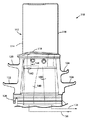
図1は、従来のバケット後縁冷却回路の、バケット内の半径方向に延びる閉ループ蛇行回路の一部を示している。バケット冷却回路の一部分だけが示されている。バケット10は、前縁14と後縁16を有する翼形部12を備える。翼形部は、翼形部フィレット19に沿って水平な翼台18に連結される。いわゆる「天使の羽」20,22及び24,26が、バケットの脚部分27の前側と後側それぞれから横方向外方に延び、そして、ダブテール部分28が、従来の方法でタービンホイール(図示せず)上にバケットを据付けるの用いられる。
【0016】
後縁冷却孔30,32(図2も参照)が、翼形部の後縁14沿いに隣接して内部に延在し、一方、内側の渡り通路34が、孔30,32の下端からバケットのダブテール部分にある冷却媒体供給通路36へと延びる。冷却用蒸気(または他の媒体)が、通路36と34を経て後縁冷却孔30,32へと流れる。冷却用蒸気は、流れを逆向きに変え(翼形部の先端にて流れが矢印で示される)、通路(図示せず)を経て半径方向内向きに進み、最終的には冷却用蒸気還流通路38へと流れる。
【0017】
製造段階で通路34を形成するコアの先端の位置を制御することが、後縁冷却孔30,32の存在ゆえに、たいへん重要であることが、図2より明らかである。また、通路34の先端とコア支持プラグ39の位置との間が比較的離れていること、すなわち、渡り通路のコアの先端の正確な位置決めに問題が多い現実も注目すべきである。
【0018】
ここで図3〜図8を参照しながら、本発明がこれらの問題点を軽減する方法について詳細に論じる。
【0019】
図3と図4では、類似した参照番号が、図1,図2における構成部分に対応する構成部分を示すように用いられるが、接頭数字「1」が付けられている。たとえば、バケット110は、前縁114と後縁116を有する翼形部112を備える。翼形部は、翼形部フィレット119に沿って翼台118に連結する。バケット110は、また、ダブテール部128だけではなく、天使の羽120,122と124,126をも有する。穿孔された孔130、132の形態で半径方向に延びる後縁冷却通路は、後縁沿いに隣接して内側に延在する。しかしながら、この構造では、冷却媒体供給通路136(図6参照)は、冷却用蒸気を一般的には天使の羽120の近くまで半径方向外方に延びる内部拡張チャンバ140に供給する。渡り通路の新設入り口142は、チャンバ140と新設渡り冷却通路144の間を水平に延び、この新設渡り冷却通路144には半径方向(または図3と図6に示すように垂直方向)の脚146と水平方向の脚148が備わり、そして、この水平方向の脚148は、翼台の下側沿いに、バケットの前部つまり前縁側から通路が後縁冷却孔130,132に交叉するバケットの後部つまり後縁側へと延びる(図5において最もわかり易い)。冷却用蒸気は、後縁沿いに半径方向外方に流れ、次に流れを逆向きに変え、半径方向内方に流れ、今度は冷却用蒸気還流通路138につながっているチャンバ150に流れ落ちる。内部バケット冷却回路用の半径方向通路のいくつかが図4に示されていて、そのうちのひとつが152で示される通路であることに注目すべきである。図5では、新設コアがどのようにして、穿孔される後縁冷却孔130,132に対して、よりわかり易い目標を提供するかを見ることができる。
【0020】
図3〜図6においては、渡り通路144が、いかにフィレット119に沿って翼形部の圧力側の輪郭に従って延びるかが明らかであり、必要とされる冷却用蒸気がフィレット119とともに翼台118の下側沿いにも供給される。渡り通路の高さが従来の装置と比べるとかなり低くなることも、図2から容易に明らかになる。
【0021】
また、図6は、通路146を内部チャンバ140に通じる入り口142に接続するように、翼形部が本体を貫いて穿孔される方法を図示する。孔は、その後154にて塞がれる。
【0022】
図7は別の装置を示し、この装置では、入り口142を介しチャンバ140と通路146とが連通するように穿孔された穴へプラグ156が挿入される。ここでは、プラグは計量孔158と160を備えて形成され、チャンバ140から通路146への空気を計量する。この装置は、流れを計量する後縁孔がない場合に特に適しており、たとえば、冷却媒体流がバケットの前縁方向へと向かいその後バケットの翼形部分の半径方向に延びる通路へと流れるような第二段バケットにおける場合である。渡り通路が形成される方法と、計量用の内部通路を形成するために取付け口が設けられる方法は、バケットを生産するのに使用される製造プロセスに依存していることが理解されるであろう。計量のための独立した機構が設けられない場合には、後縁孔130,132が冷却空気を計量できるような寸法に作られる。
【0023】
図8は、蛇行形状をした別の渡り通路254を開示しており、より広い範囲の翼台218の冷却を可能にしている。所望に応じ、翼台/フィレット領域を冷却するのに、様々な設計構成を実行しうることが解るであろう。
【0024】
本発明は現在もっとも実用的で好ましいと思われる実施形態に関して述べられてきたが、本発明は、開示された実施形態に限定されず、むしろ特許請求の範囲の技術思想及び技術的範囲内に属する様々な変形態様及び同等の装置を網羅するよう意図されていることが理解されるであろう。
【図面の簡単な説明】
【図1】 従来のガスタービンバケットの一部切除斜視図
【図2】 図1に示されたバケットの部分平面図
【図3】 本発明によるガスタービンバケットの内部冷却回路の部分側面図。
【図4】 本発明によるガスタービンバケットの翼先端キャップを取除いた平面図。
【図5】 図4に示されるガスタービンバケットの半径方向のバケット翼台に近い位置で見た部分断面図。
【図6】 図4に示すガスタービンバケットの線6−6に沿った横断面図。
【図7】 変更した計量プラグを設けた、図6の拡大詳細図。
【図8】 本発明の別の実施形態の部分斜視図。[0001]
BACKGROUND OF THE INVENTION
The present invention relates to a closed loop convection cooled gas turbine bucket and a method for cooling a bucket tail and airfoil fillet region.
[0002]
[Prior art]
Gas turbine bucket technology continues to advance. According to current design technology, advanced closed-loop cooling systems, higher combustion temperatures, and new materials are incorporated to achieve higher thermal efficiency. Concurrent with these advances, there is a continuing need for component designs that prevent cracking due to low cycle fatigue and subsequent loss of coolant.
[0003]
Low cycle fatigue (LCF) is a mechanical structural defect common to all gas turbine buckets. Low cycle fatigue is defined as damage caused by the periodic reverse plastic flow of metal in a component exposed to a duty cycle less than 10,000 duty cycles. Low cycle fatigue stress is a function of both temperature and stress within the section. Stress can arise from mechanical loads such as pressure, gas bending or centrifugal forces, and stress can be caused by metal temperature differences between various regions and geometric constraints between these regions. It can also be induced and generated. Minimizing the thermal gradient in the structure is the key to reducing LCF damage.
[0004]
In advanced gas turbine cooling bucket designs, particularly with thermal barrier coatings, the temperature of the majority of the airfoil tends to be lower than the base of the airfoil, which is And a thermal stress is generated in the airfoil fillet region on the pressure side of the airfoil (where the airfoil portion is connected to the blade base). Sufficient cooling of this region is necessary to reduce stress and improve low cycle fatigue life.
[0005]
The transition core, which creates a cavity through which the cooling medium is machined to the trailing edge hole, is secured in the shell structure at the base of the bucket during casting of the bucket. The transition path core is also supported by the shell at two locations in the middle of the span (see the transition path core support shown in FIG. 1) and at another location near the tip of the transition path core.
[0006]
It is this position that is the target for drilling the trailing edge cooling hole in the bucket airfoil, so it is very important to control the position of the tip of the core. These machined trailing edge cooling holes must intersect the tip of this core to allow the cooling medium to flow through the holes and to supply the cooling medium to the trailing edge of the airfoil. One of the root causes of poor position control is inherent in the design. In particular, there is a difference in thermal expansion between the ceramic shell and the ceramic core used in the casting process, and because the transition path core is relatively long (about 12 inches), the transition path core is It is “pulled” by the end of its root that is fixed to. This design to try to fix at the tip was attempted but failed because the core was easily broken.
[0007]
[Problems to be solved by the invention]
The present invention seeks to enhance the performance of turbine buckets against low cycle fatigue by using an improved cooling system that is more manufacturable and cost effective. The design and manufacturing improvements are summarized below.
[0008]
[Means for Solving the Problems]
In terms of design, a transition passage opens into a cooling passage in the leg of the bucket at a location near the underside of the blade platform and then extends along the underside of the blade platform in the direction of the trailing edge of the airfoil. This arrangement cools both the blade platform and the airfoil fillet region. For the second stage bucket, the direction of flow may be from the rear of the bucket toward the leading edge, where the flow flows into a radially extending cooling passage of the bucket airfoil.
[0009]
This design change means that the overall height of the core used in the bucket manufacturing can be reduced and the temperature variation can be reduced. The redesigned transit core can be secured in the shell at the front or radially outer core end, thus solving the problem of conventional core end location. There is no concern about the relative movement of the two cores in the radial direction because the transition path core directly hits the main body core. The pass-through core can float at the rear or radially inner core position. However, since the core is completely encased by the shell and in the immediate vicinity of the platform, the relative movement between the core and the platform is reduced, and with it, it can be expected that dimensional control is improved. A further advantage of this design is light weight, mainly due to the smaller central ribs of the bucket legs.
[0010]
This design concept can also be implemented as a post-cast assembly rather than a cast. In any case, the manufacturing process used to produce this new bucket platform cooling circuit is not considered part of the invention itself.
[0011]
The internal heat transfer coefficient of the new transfer passage design can be optimized by adjusting either the cross-sectional area or wetting, thus controlling the flow rate and heat transfer coefficient. Furthermore, the passage, in order to increase the local heat transfer coefficients without causing unnecessary increase in the pressure loss and heat release over passages throughout, it is also possible to locally vortex structure.
[0012]
According to another design within the scope of the present invention, it is possible to cool virtually any part of the blade platform by simply changing the course of the transition path along the blade platform underside. It is also assumed that the cooling steam is metered by the cooling holes themselves and flows into the trailing edge holes. In the absence of a trailing edge hole capable of metering the cooling flow, the flow around the main cooling circuit is too large and is a dimensional constraint that is set to the minimum cross-sectional area of the passageway to meet the manufacturability of a suitable core Would not suit. Thus, such a use case is provided with an independent means for metering the flow to the trailing edge hole.
[0013]
Accordingly, in a broader aspect of the present invention, the present invention is a closed circuit steam cooling device in a gas turbine bucket having an airfoil portion connected to a blade platform along a fillet region, wherein the steam cooling supply passage is for cooling. The present invention relates to a closed circuit steam cooler that is adapted to supply steam to an airfoil portion of a bucket and that also includes a transition passage that extends adjacent and substantially parallel to the blade platform.
[0014]
In another aspect, the invention also includes an airfoil portion having a leading edge and a trailing edge, and at least one radial extension in the airfoil portion coupled to the airfoil at a radially inner end of the airfoil portion. A transition having a portion that is in fluid communication with the cooling passage, the dovetail mounting portion that includes the cooling medium supply passage, and the cooling medium supply passage and at least one radially extending cooling passage, and that extends substantially parallel along the underside of the blade platform. A turbine bucket provided with a passage.
[0015]
DETAILED DESCRIPTION OF THE INVENTION
FIG. 1 shows a portion of a conventional bucket trailing edge cooling circuit, a radially extending closed loop serpentine circuit within the bucket. Only a portion of the bucket cooling circuit is shown.
[0016]
Trailing edge cooling holes 30 and 32 (see also FIG. 2) extend inward and adjacent along the trailing
[0017]
It is clear from FIG. 2 that it is very important to control the position of the tip of the core that forms the
[0018]
Referring now to FIGS. 3-8, the manner in which the present invention mitigates these problems will be discussed in detail.
[0019]
3 and 4, similar reference numbers are used to indicate components corresponding to those in FIGS. 1 and 2, but are prefixed with “1”. For example,
[0020]
In FIGS. 3-6, it is clear how the
[0021]
FIG. 6 also illustrates the manner in which the airfoil is drilled through the body to connect the
[0022]
FIG. 7 shows another device in which a
[0023]
FIG. 8 discloses another
[0024]
Although the invention has been described with reference to the most practical and preferred embodiment at present, the invention is not limited to the disclosed embodiment but rather falls within the spirit and scope of the appended claims. It will be understood that various modifications and equivalent devices are intended to be covered.
[Brief description of the drawings]
1 is a partially cutaway perspective view of a conventional gas turbine bucket. FIG. 2 is a partial plan view of the bucket shown in FIG. 1. FIG. 3 is a partial side view of an internal cooling circuit of a gas turbine bucket according to the present invention.
FIG. 4 is a plan view of the gas turbine bucket according to the present invention with the blade tip cap removed.
5 is a partial cross-sectional view of the gas turbine bucket shown in FIG. 4 as seen at a position close to a bucket blade base in the radial direction.
6 is a cross-sectional view of the gas turbine bucket shown in FIG. 4 taken along line 6-6.
7 is an enlarged detail view of FIG. 6 provided with a modified metering plug.
FIG. 8 is a partial perspective view of another embodiment of the present invention.
Claims (7)
a)前記バケット(110)のダブテール据付部分に冷却媒体供給通路(136)を設ける段階と、
b)前記冷却媒体供給通路(136)と前記少なくとも1つの半径方向に延びる冷却通路(130)とを連結する渡り通路(144)を設ける段階と、
c)前記渡り通路(144)を、前記バケット(110)の圧力側に沿って前記翼台(118)及びフィレット領域(119)を冷却するため前記翼台(118)の下側沿いに実質的に平行に延びるように配設する段階であって、前記渡り通路(144)がフィレット領域(119)沿いに翼形部分(112)の圧力側の輪郭に沿って延びるとともに、翼形部分の後縁(116)の下方を圧力側から負圧側へと横断して、後縁冷却孔(130、132)と実質的に90度の角度で交叉するように配設する段階と
を含む方法。A method for cooling a turbine bucket tail (118) in a turbine bucket (110) having an internal cooling circuit including at least one radially extending cooling passage (130) comprising:
a) providing a cooling medium supply passage (136) in a dovetail installation portion of the bucket (110) ;
b) providing a transition passage (144) connecting the cooling medium supply passage (136) and the at least one radially extending cooling passage (130);
c) passing through (144) substantially along the underside of the platform (118) to cool the platform (118) and fillet region (119) along the pressure side of the bucket (110) ; The transition passage (144) extends along the pressure side contour of the airfoil portion (112) along the fillet region (119) and after the airfoil portion. Disposing under the edge (116) from the pressure side to the suction side and intersecting the trailing edge cooling holes (130, 132) at a substantially 90 degree angle .
Applications Claiming Priority (2)
| Application Number | Priority Date | Filing Date | Title |
|---|---|---|---|
| US09/496715 | 2000-02-02 | ||
| US09/496,715 US6390774B1 (en) | 2000-02-02 | 2000-02-02 | Gas turbine bucket cooling circuit and related process |
Publications (3)
| Publication Number | Publication Date |
|---|---|
| JP2001214703A JP2001214703A (en) | 2001-08-10 |
| JP2001214703A5 JP2001214703A5 (en) | 2007-11-15 |
| JP4731001B2 true JP4731001B2 (en) | 2011-07-20 |
Family
ID=23973815
Family Applications (1)
| Application Number | Title | Priority Date | Filing Date |
|---|---|---|---|
| JP2000297789A Expired - Lifetime JP4731001B2 (en) | 2000-02-02 | 2000-09-29 | Gas turbine bucket cooling circuit and cooling method |
Country Status (7)
| Country | Link |
|---|---|
| US (1) | US6390774B1 (en) |
| EP (1) | EP1122405B1 (en) |
| JP (1) | JP4731001B2 (en) |
| KR (1) | KR20010077887A (en) |
| AT (1) | ATE491080T1 (en) |
| CZ (1) | CZ20003307A3 (en) |
| DE (1) | DE60045333D1 (en) |
Families Citing this family (44)
| Publication number | Priority date | Publication date | Assignee | Title |
|---|---|---|---|---|
| US6932570B2 (en) * | 2002-05-23 | 2005-08-23 | General Electric Company | Methods and apparatus for extending gas turbine engine airfoils useful life |
| US6832893B2 (en) * | 2002-10-24 | 2004-12-21 | Pratt & Whitney Canada Corp. | Blade passive cooling feature |
| US20040169013A1 (en) * | 2003-02-28 | 2004-09-02 | General Electric Company | Method for chemically removing aluminum-containing materials from a substrate |
| US6773229B1 (en) | 2003-03-14 | 2004-08-10 | General Electric Company | Turbine nozzle having angel wing seal lands and associated welding method |
| US20050000674A1 (en) * | 2003-07-01 | 2005-01-06 | Beddard Thomas Bradley | Perimeter-cooled stage 1 bucket core stabilizing device and related method |
| US6966756B2 (en) * | 2004-01-09 | 2005-11-22 | General Electric Company | Turbine bucket cooling passages and internal core for producing the passages |
| US7097424B2 (en) | 2004-02-03 | 2006-08-29 | United Technologies Corporation | Micro-circuit platform |
| US7097417B2 (en) * | 2004-02-09 | 2006-08-29 | Siemens Westinghouse Power Corporation | Cooling system for an airfoil vane |
| US7207775B2 (en) * | 2004-06-03 | 2007-04-24 | General Electric Company | Turbine bucket with optimized cooling circuit |
| US7147439B2 (en) * | 2004-09-15 | 2006-12-12 | General Electric Company | Apparatus and methods for cooling turbine bucket platforms |
| FR2877034B1 (en) * | 2004-10-27 | 2009-04-03 | Snecma Moteurs Sa | ROTOR BLADE OF A GAS TURBINE |
| US7255535B2 (en) * | 2004-12-02 | 2007-08-14 | Albrecht Harry A | Cooling systems for stacked laminate CMC vane |
| US7153096B2 (en) * | 2004-12-02 | 2006-12-26 | Siemens Power Generation, Inc. | Stacked laminate CMC turbine vane |
| US7198458B2 (en) | 2004-12-02 | 2007-04-03 | Siemens Power Generation, Inc. | Fail safe cooling system for turbine vanes |
| US7255536B2 (en) | 2005-05-23 | 2007-08-14 | United Technologies Corporation | Turbine airfoil platform cooling circuit |
| US7465152B2 (en) * | 2005-09-16 | 2008-12-16 | General Electric Company | Angel wing seals for turbine blades and methods for selecting stator, rotor and wing seal profiles |
| US7309212B2 (en) * | 2005-11-21 | 2007-12-18 | General Electric Company | Gas turbine bucket with cooled platform leading edge and method of cooling platform leading edge |
| US7695246B2 (en) * | 2006-01-31 | 2010-04-13 | United Technologies Corporation | Microcircuits for small engines |
| US7416391B2 (en) * | 2006-02-24 | 2008-08-26 | General Electric Company | Bucket platform cooling circuit and method |
| US7766606B2 (en) * | 2006-08-17 | 2010-08-03 | Siemens Energy, Inc. | Turbine airfoil cooling system with platform cooling channels with diffusion slots |
| US20100034662A1 (en) * | 2006-12-26 | 2010-02-11 | General Electric Company | Cooled airfoil and method for making an airfoil having reduced trail edge slot flow |
| US8052395B2 (en) * | 2007-09-28 | 2011-11-08 | General Electric Company | Air cooled bucket for a turbine |
| US8147188B2 (en) * | 2007-09-28 | 2012-04-03 | General Electric Company | Air cooled bucket for a turbine |
| US8511990B2 (en) * | 2009-06-24 | 2013-08-20 | General Electric Company | Cooling hole exits for a turbine bucket tip shroud |
| US8523527B2 (en) * | 2010-03-10 | 2013-09-03 | General Electric Company | Apparatus for cooling a platform of a turbine component |
| US8647064B2 (en) | 2010-08-09 | 2014-02-11 | General Electric Company | Bucket assembly cooling apparatus and method for forming the bucket assembly |
| US9416666B2 (en) | 2010-09-09 | 2016-08-16 | General Electric Company | Turbine blade platform cooling systems |
| US8814518B2 (en) * | 2010-10-29 | 2014-08-26 | General Electric Company | Apparatus and methods for cooling platform regions of turbine rotor blades |
| US8636471B2 (en) * | 2010-12-20 | 2014-01-28 | General Electric Company | Apparatus and methods for cooling platform regions of turbine rotor blades |
| US8628300B2 (en) * | 2010-12-30 | 2014-01-14 | General Electric Company | Apparatus and methods for cooling platform regions of turbine rotor blades |
| US8753083B2 (en) | 2011-01-14 | 2014-06-17 | General Electric Company | Curved cooling passages for a turbine component |
| US9447691B2 (en) * | 2011-08-22 | 2016-09-20 | General Electric Company | Bucket assembly treating apparatus and method for treating bucket assembly |
| US8858160B2 (en) * | 2011-11-04 | 2014-10-14 | General Electric Company | Bucket assembly for turbine system |
| US9022735B2 (en) * | 2011-11-08 | 2015-05-05 | General Electric Company | Turbomachine component and method of connecting cooling circuits of a turbomachine component |
| US9127561B2 (en) | 2012-03-01 | 2015-09-08 | General Electric Company | Turbine bucket with contoured internal rib |
| US8974182B2 (en) | 2012-03-01 | 2015-03-10 | General Electric Company | Turbine bucket with a core cavity having a contoured turn |
| US9109454B2 (en) * | 2012-03-01 | 2015-08-18 | General Electric Company | Turbine bucket with pressure side cooling |
| US9638051B2 (en) | 2013-09-04 | 2017-05-02 | General Electric Company | Turbomachine bucket having angel wing for differently sized discouragers and related methods |
| US9810072B2 (en) | 2014-05-28 | 2017-11-07 | General Electric Company | Rotor blade cooling |
| CN106715834B (en) | 2014-09-18 | 2019-01-08 | 西门子公司 | Aerofoil profile in gas-turbine unit and the cored structure for being used to form this aerofoil profile |
| US20190085706A1 (en) * | 2017-09-18 | 2019-03-21 | General Electric Company | Turbine engine airfoil assembly |
| US10731475B2 (en) | 2018-04-20 | 2020-08-04 | Raytheon Technologies Corporation | Blade with inlet orifice on aft face of root |
| JP7129277B2 (en) * | 2018-08-24 | 2022-09-01 | 三菱重工業株式会社 | airfoil and gas turbine |
| CN118339363A (en) | 2021-12-28 | 2024-07-12 | 三菱重工业株式会社 | Rotating blade and gas turbine equipped with the same |
Family Cites Families (22)
| Publication number | Priority date | Publication date | Assignee | Title |
|---|---|---|---|---|
| GB754217A (en) | 1953-01-30 | 1956-08-08 | Gen Motors Corp | Improvements relating to turbine blades |
| US3844679A (en) | 1973-03-28 | 1974-10-29 | Gen Electric | Pressurized serpentine cooling channel construction for open-circuit liquid cooled turbine buckets |
| US4212587A (en) * | 1978-05-30 | 1980-07-15 | General Electric Company | Cooling system for a gas turbine using V-shaped notch weirs |
| US4242045A (en) * | 1979-06-01 | 1980-12-30 | General Electric Company | Trap seal for open circuit liquid cooled turbines |
| US4244676A (en) * | 1979-06-01 | 1981-01-13 | General Electric Company | Cooling system for a gas turbine using a cylindrical insert having V-shaped notch weirs |
| GB2082257B (en) | 1980-08-08 | 1984-02-15 | Gen Electric | Liquid coolant distribution systems for gas turbines |
| US4775296A (en) * | 1981-12-28 | 1988-10-04 | United Technologies Corporation | Coolable airfoil for a rotary machine |
| JPS61205301A (en) * | 1985-03-06 | 1986-09-11 | Hitachi Ltd | Gas turbine blade |
| US5340278A (en) * | 1992-11-24 | 1994-08-23 | United Technologies Corporation | Rotor blade with integral platform and a fillet cooling passage |
| JPH07119405A (en) * | 1993-10-26 | 1995-05-09 | Hitachi Ltd | Gas turbine cooling blades |
| US5491971A (en) | 1993-12-23 | 1996-02-20 | General Electric Co. | Closed circuit air cooled gas turbine combined cycle |
| US5591002A (en) | 1994-08-23 | 1997-01-07 | General Electric Co. | Closed or open air cooling circuits for nozzle segments with wheelspace purge |
| US5536143A (en) | 1995-03-31 | 1996-07-16 | General Electric Co. | Closed circuit steam cooled bucket |
| JP2851578B2 (en) * | 1996-03-12 | 1999-01-27 | 三菱重工業株式会社 | Gas turbine blades |
| JP3426841B2 (en) | 1996-04-15 | 2003-07-14 | 三菱重工業株式会社 | Gas turbine blade |
| US5823741A (en) | 1996-09-25 | 1998-10-20 | General Electric Co. | Cooling joint connection for abutting segments in a gas turbine engine |
| DE19713268B4 (en) | 1997-03-29 | 2006-01-19 | Alstom | Chilled gas turbine blade |
| US5915923A (en) * | 1997-05-22 | 1999-06-29 | Mitsubishi Heavy Industries, Ltd. | Gas turbine moving blade |
| US6190130B1 (en) | 1998-03-03 | 2001-02-20 | Mitsubishi Heavy Industries, Ltd. | Gas turbine moving blade platform |
| US6065931A (en) * | 1998-03-05 | 2000-05-23 | Mitsubishi Heavy Industries, Ltd. | Gas turbine moving blade |
| US6092991A (en) * | 1998-03-05 | 2000-07-25 | Mitsubishi Heavy Industries, Ltd. | Gas turbine blade |
| CA2231988C (en) | 1998-03-12 | 2002-05-28 | Mitsubishi Heavy Industries, Ltd. | Gas turbine blade |
-
2000
- 2000-02-02 US US09/496,715 patent/US6390774B1/en not_active Expired - Lifetime
- 2000-09-11 CZ CZ20003307A patent/CZ20003307A3/en unknown
- 2000-09-29 KR KR1020000057411A patent/KR20010077887A/en not_active Ceased
- 2000-09-29 EP EP00308612A patent/EP1122405B1/en not_active Expired - Lifetime
- 2000-09-29 JP JP2000297789A patent/JP4731001B2/en not_active Expired - Lifetime
- 2000-09-29 DE DE60045333T patent/DE60045333D1/en not_active Expired - Lifetime
- 2000-09-29 AT AT00308612T patent/ATE491080T1/en not_active IP Right Cessation
Also Published As
| Publication number | Publication date |
|---|---|
| EP1122405A3 (en) | 2004-01-07 |
| CZ20003307A3 (en) | 2001-09-12 |
| ATE491080T1 (en) | 2010-12-15 |
| KR20010077887A (en) | 2001-08-20 |
| EP1122405A2 (en) | 2001-08-08 |
| JP2001214703A (en) | 2001-08-10 |
| US6390774B1 (en) | 2002-05-21 |
| EP1122405B1 (en) | 2010-12-08 |
| DE60045333D1 (en) | 2011-01-20 |
Similar Documents
| Publication | Publication Date | Title |
|---|---|---|
| JP4731001B2 (en) | Gas turbine bucket cooling circuit and cooling method | |
| US5348446A (en) | Bimetallic turbine airfoil | |
| JP5185569B2 (en) | Meander cooling circuit and method for cooling shroud | |
| JP4571277B2 (en) | Gas turbine blade with impingement cooling platform | |
| US7717676B2 (en) | High aspect ratio blade main core modifications for peripheral serpentine microcircuits | |
| CN1690364B (en) | Turbulator on the underside of a turbine blade tip turn and related method | |
| US7033136B2 (en) | Cooling circuits for a gas turbine blade | |
| EP2246133B1 (en) | RMC-defined tip blowing slots for turbine blades | |
| US7255536B2 (en) | Turbine airfoil platform cooling circuit | |
| JP3053174B2 (en) | Wing for use in turbomachine and method of manufacturing the same | |
| US7980822B2 (en) | Multi-peripheral serpentine microcircuits for high aspect ratio blades | |
| JP5911680B2 (en) | Bucket assembly cooling device and method for forming bucket assembly | |
| JP2007205352A (en) | Turbine engine component for small engine and its design method | |
| US20070128031A1 (en) | Turbine airfoil with outer wall cooling system and inner mid-chord hot gas receiving cavity | |
| JPH09511041A (en) | Turbine vanes with platform cavities for dual supply of cooling fluid | |
| JP2001107702A (en) | Insulation coated squealer tip cavity | |
| JP2004521219A (en) | Impingement cooling system for turbine bucket platform | |
| CN102619574B (en) | For cooling down the Apparatus and method in turbine rotor blade platform district | |
| JP2006177347A (en) | Turbine vane of gas turbine engine, turbomachine element, and reconstitution method for form | |
| CN103790641B (en) | Turbine blade tip shroud | |
| JP2001173404A (en) | Gas turbine bucket wall thickness control | |
| US20080008599A1 (en) | Integral main body-tip microcircuits for blades | |
| JPS6148610B2 (en) | ||
| US7192251B1 (en) | Air deflector for a cooling circuit for a gas turbine blade | |
| JPH11193701A (en) | Turbine blade |
Legal Events
| Date | Code | Title | Description |
|---|---|---|---|
| A521 | Request for written amendment filed |
Free format text: JAPANESE INTERMEDIATE CODE: A523 Effective date: 20071001 |
|
| A621 | Written request for application examination |
Free format text: JAPANESE INTERMEDIATE CODE: A621 Effective date: 20071001 |
|
| RD02 | Notification of acceptance of power of attorney |
Free format text: JAPANESE INTERMEDIATE CODE: A7422 Effective date: 20090918 |
|
| RD04 | Notification of resignation of power of attorney |
Free format text: JAPANESE INTERMEDIATE CODE: A7424 Effective date: 20090918 |
|
| A131 | Notification of reasons for refusal |
Free format text: JAPANESE INTERMEDIATE CODE: A131 Effective date: 20100615 |
|
| A601 | Written request for extension of time |
Free format text: JAPANESE INTERMEDIATE CODE: A601 Effective date: 20100915 |
|
| A602 | Written permission of extension of time |
Free format text: JAPANESE INTERMEDIATE CODE: A602 Effective date: 20100921 |
|
| A521 | Request for written amendment filed |
Free format text: JAPANESE INTERMEDIATE CODE: A523 Effective date: 20101215 |
|
| TRDD | Decision of grant or rejection written | ||
| A01 | Written decision to grant a patent or to grant a registration (utility model) |
Free format text: JAPANESE INTERMEDIATE CODE: A01 Effective date: 20110322 |
|
| A61 | First payment of annual fees (during grant procedure) |
Free format text: JAPANESE INTERMEDIATE CODE: A61 Effective date: 20110419 |
|
| FPAY | Renewal fee payment (event date is renewal date of database) |
Free format text: PAYMENT UNTIL: 20140428 Year of fee payment: 3 |
|
| R150 | Certificate of patent or registration of utility model |
Ref document number: 4731001 Country of ref document: JP Free format text: JAPANESE INTERMEDIATE CODE: R150 Free format text: JAPANESE INTERMEDIATE CODE: R150 |
|
| R250 | Receipt of annual fees |
Free format text: JAPANESE INTERMEDIATE CODE: R250 |
|
| R250 | Receipt of annual fees |
Free format text: JAPANESE INTERMEDIATE CODE: R250 |
|
| R250 | Receipt of annual fees |
Free format text: JAPANESE INTERMEDIATE CODE: R250 |
|
| R250 | Receipt of annual fees |
Free format text: JAPANESE INTERMEDIATE CODE: R250 |
|
| R250 | Receipt of annual fees |
Free format text: JAPANESE INTERMEDIATE CODE: R250 |
|
| R250 | Receipt of annual fees |
Free format text: JAPANESE INTERMEDIATE CODE: R250 |
|
| R250 | Receipt of annual fees |
Free format text: JAPANESE INTERMEDIATE CODE: R250 |