JP4731455B2 - Corrosion test method and apparatus - Google Patents
Corrosion test method and apparatus Download PDFInfo
- Publication number
- JP4731455B2 JP4731455B2 JP2006340940A JP2006340940A JP4731455B2 JP 4731455 B2 JP4731455 B2 JP 4731455B2 JP 2006340940 A JP2006340940 A JP 2006340940A JP 2006340940 A JP2006340940 A JP 2006340940A JP 4731455 B2 JP4731455 B2 JP 4731455B2
- Authority
- JP
- Japan
- Prior art keywords
- test
- electrolyte
- temperature
- water vapor
- corrosion
- Prior art date
- Legal status (The legal status is an assumption and is not a legal conclusion. Google has not performed a legal analysis and makes no representation as to the accuracy of the status listed.)
- Expired - Fee Related
Links
Images


Landscapes
- Testing Resistance To Weather, Investigating Materials By Mechanical Methods (AREA)
Description
本発明は、腐食試験方法及び装置に係り、特に、電子機器等の設置環境に依存して生じる腐食(大気腐食)に対する長期的な信頼性を評価する腐食試験方法及び装置に関する。 The present invention relates to a corrosion test method and apparatus, and more particularly to a corrosion test method and apparatus for evaluating long-term reliability against corrosion (atmospheric corrosion) that occurs depending on the installation environment of an electronic device or the like.
公衆電話ボックスや無人の電気通信用建屋などの直接外気の影響を受ける場所で使用する電子機器等では、大気腐食に対する長期的な信頼性を評価する必要がある。 It is necessary to evaluate long-term reliability against atmospheric corrosion in electronic equipment used in places affected by direct outside air such as public telephone boxes and unmanned telecommunication buildings.
腐食試験としては、JISで定められているものとして、塩水噴霧試験(JIS Z 2371)や湿潤試験(JIS K 2246、JIS K 5600−7−2)などがある。 As the corrosion test, there are a salt spray test (JIS Z 2371), a wet test (JIS K 2246, JIS K 5600-7-2) and the like as defined by JIS.
塩水噴霧試験は、食塩水(5wt%−NaCl)を試料表面に噴霧(80cm2当たり1.5ml/h(降水量として、時間当たり0.19mm/cm2))して生じた腐食の面積から耐蝕性を判定するものである。試験時間は、概ね150h以下であり、電子機器関連部品の試験では50h程度である。 The salt spray test is based on the area of corrosion caused by spraying saline (5 wt% -NaCl) onto the sample surface (1.5 ml / h per 80 cm 2 (0.19 mm / cm 2 per hour as precipitation)). Corrosion resistance is judged. The test time is approximately 150 hours or less, and about 50 hours in the test of electronic equipment related parts.
しかしながら、表面吸着水が生じるとされる相対湿度80%RHが、年間1500hを超える日本(北海道を除く)において、製品寿命として5年を考えた場合、上記の試験時間は7500h(1500h×5)と比較して著しく短い。
However, in Japan (excluding Hokkaido) where the
また、塩水噴霧試験を大気腐食の加速試験として用いる場合の加速係数も明らかになっておらず、米国の塩水噴霧試験規格であるASTM B 117−03(邦訳版)には、「自然環境における性能の予測は、単独のデータとして使用された場合、ほとんど塩水噴霧の結果と相関されたことはない」とも記載されている。 In addition, the acceleration coefficient when the salt spray test is used as an acceleration test for atmospheric corrosion has not been clarified, and ASTM B 117-03 (Japanese translation version), which is the US salt spray test standard, states that “performance in the natural environment”. "When used as stand-alone data, it is rarely correlated with salt spray results".
一方、湿潤試験(JIS K 2246)は、試料(さび止め油)を被覆した試験片を湿潤状態に規定時間保持した後のさびの発生度を調べるものである。なお、JIS K 2246、JIS K 5600−7−2では、温度50±1℃、湿度95%RH以上の湿潤環境で評価することを規定している。 On the other hand, the wet test (JIS K 2246) is a test for examining the degree of rust after a test piece coated with a sample (rust prevention oil) is kept in a wet state for a specified time. In addition, JIS K 2246 and JIS K 5600-7-2 stipulate that the evaluation is performed in a humid environment having a temperature of 50 ± 1 ° C. and a humidity of 95% RH or more.
しかしながら、湿潤試験では、蒸留水(脱イオン水)での加湿となるため、試験雰囲気中に電解質の存在が無く、大気腐食環境を再現できない。また、仮に、湿潤試験で加湿に用いる水にNaCl水溶液を用いた場合においても、その水蒸気にはNaClが含まれないことから大気腐食環境を試験装置内で実現することはできない。
このように、従来の塩水噴霧試験や湿潤試験は、大気腐食環境を十分に反映したものではなく、大気中で使用される電子機器等の信頼性を評価するための腐食試験としては不十分であった。また、従来の湿潤試験では、試験装置内に大気腐食環境を実現することはできなかった。 As described above, the conventional salt spray test and the wet test do not sufficiently reflect the atmospheric corrosion environment, and are insufficient as a corrosion test for evaluating the reliability of electronic devices used in the atmosphere. there were. Further, in the conventional wet test, it was impossible to realize an atmospheric corrosion environment in the test apparatus.
本発明の目的は、試験装置内に大気腐食環境を実現し、大気腐食環境を十分に反映した試験を行うことができる腐食試験方法及び装置を提供することにある。 An object of the present invention is to provide a corrosion test method and apparatus capable of realizing an atmospheric corrosion environment in a test apparatus and performing a test sufficiently reflecting the atmospheric corrosion environment.
本発明の一観点によれば、電解質の水溶液を霧化して前記電解質を含む霧粒子を生成し、前記電解質を含む霧粒子を加熱して前記電解質を含む水蒸気を生成し、前記電解質を含む水蒸気に試験試料を暴露し、前記試験試料の耐腐食性を評価することを特徴とする腐食試験方法が提供される。 According to one aspect of the present invention, an aqueous solution of an electrolyte is atomized to produce mist particles containing the electrolyte, the mist particles containing the electrolyte are heated to produce water vapor containing the electrolyte, and water vapor containing the electrolyte. A corrosion test method is provided, which comprises exposing a test sample to a test sample and evaluating the corrosion resistance of the test sample.
また、本発明の他の観点によれば、試験試料を設置する試験槽と、電解質の水溶液を霧化して前記電解質を含む霧粒子を生成する霧化器と、前記電解質を含む霧粒子を加熱して前記電解質を含む水蒸気を生成し、前記試験槽に導入する加熱器とを有することを特徴とする腐食試験装置が提供される。 According to another aspect of the present invention, a test tank in which a test sample is installed, an atomizer that atomizes an aqueous solution of an electrolyte to generate mist particles including the electrolyte, and heats the mist particles including the electrolyte. And a heater for generating water vapor containing the electrolyte and introducing it into the test tank.
また、本発明の更に他の観点によれば、電解質を含む水蒸気が存在する試験雰囲気の形成方法であって、電解質の水溶液を霧化して前記電解質を含む霧粒子を生成し、前記電解質を含む霧粒子を加熱して前記電解質を含む水蒸気を生成する試験雰囲気の形成方法が提供される。 According to still another aspect of the present invention, there is provided a method for forming a test atmosphere in which water vapor containing an electrolyte is present, wherein an aqueous solution of the electrolyte is atomized to produce mist particles containing the electrolyte, and the electrolyte is contained. There is provided a method for forming a test atmosphere in which fog particles are heated to generate water vapor containing the electrolyte.
また、本発明の更に他の観点によれば、電解質を含む水蒸気が存在する試験雰囲気を形成する試験雰囲気形成装置であって、電解質の水溶液を霧化して前記電解質を含む霧粒子を生成する霧化器と、前記電解質を含む霧粒子を加熱して前記電解質を含む水蒸気を生成する加熱器とを有する試験雰囲気形成装置が提供される。 According to yet another aspect of the present invention, there is provided a test atmosphere forming apparatus for forming a test atmosphere in which water vapor containing an electrolyte is present, wherein the fog is generated by atomizing an aqueous solution of the electrolyte to produce the electrolyte. There is provided a test atmosphere forming apparatus having a generator and a heater that heats fog particles containing the electrolyte to generate water vapor containing the electrolyte.
本発明によれば、電解質の水溶液を霧化して電解質を含む霧粒子を生成し、電解質を含む霧粒子を加熱して電解質を含む水蒸気を生成することにより、試験環境を形成するので、実際の大気と同様の、表面吸着水と大気浮遊塩とが共存する試験環境を容易に実現することができる。これにより、大気腐食環境を十分に反映した腐食試験を行うことができる。 According to the present invention, a test environment is formed by atomizing an aqueous solution of an electrolyte to produce fog particles containing the electrolyte, and heating the fog particles containing the electrolyte to produce water vapor containing the electrolyte. A test environment in which surface adsorbed water and atmospheric suspended salt coexist can be easily realized as in the atmosphere. As a result, a corrosion test that sufficiently reflects the atmospheric corrosion environment can be performed.
また、試験環境に応じて、電解質を含む水蒸気を安定して供給することができる。これにより、表面吸着水と電解質が共存する大気腐食環境を、例えばJISの湿潤試験と同じ温湿度条件で、安定して構築することができる。 Further, it is possible to stably supply water vapor containing an electrolyte according to the test environment. Thereby, an atmospheric corrosion environment where surface adsorbed water and an electrolyte coexist can be stably constructed, for example, under the same temperature and humidity conditions as in the JIS wet test.
その結果、ボックスや無人の電気通信用建屋に代表される電子機器が直接外気の影響を受ける場所での大気腐食を再現でき、従来の湿潤試験や塩水噴霧試験では明らかにできなかった電子機器の設置環境に依存して生じる腐食について、長期的なデータを取得することができ、電子機器の長期信頼性を向上することができる。 As a result, electronic devices such as boxes and unmanned telecommunications buildings can reproduce atmospheric corrosion in locations directly affected by outside air, and electronic devices that could not be revealed by conventional wet tests and salt spray tests. Long-term data can be acquired for corrosion that occurs depending on the installation environment, and long-term reliability of the electronic device can be improved.
[第1実施形態]
本発明の第1実施形態による腐食試験方法及び装置について図1乃至図3を用いて説明する。
[First Embodiment]
A corrosion test method and apparatus according to a first embodiment of the present invention will be described with reference to FIGS.
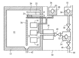
図1は本実施形態による腐食試験装置の構造を示す概略図、図2は本実施形態による腐食試験方法を示すフローチャート、図3は電解質を含む霧粒子の加熱に伴う挙動を説明する図である。 FIG. 1 is a schematic diagram showing the structure of a corrosion test apparatus according to the present embodiment, FIG. 2 is a flowchart showing a corrosion test method according to the present embodiment, and FIG. 3 is a diagram for explaining the behavior accompanying heating of fog particles containing an electrolyte. .
はじめに、本実施形態による腐食試験装置について図1を用いて説明する。 First, the corrosion test apparatus according to the present embodiment will be described with reference to FIG.
試験試料を設置する試験槽10は、断熱材よりなる断熱壁12によって囲まれている。試験槽10内には、調温/調湿室14が設けられている。試験槽10内において、仕切り28を隔てて調温/調湿室14に隣接する空間が、試験試料を設置する空間である。
The
仕切り28を設けているのは、調温/調湿室14で温度/湿度をコントロールした(加湿)空気を、試料を設置する空間に導入した方が、温度/湿度を高精度にコントロールできるからである。例えば、大容量/大容積の試験槽10の全体を一隅からコントロールしようとした場合、温度/湿度の設定値に安定するまでの所要時間が大きくなるからである。
The
調温/調湿室14内には、除湿/冷却器16と、加湿器17と、加熱器18とが設置されている。また、試験槽10内には、乾球温度センサ20と湿球温度センサ22とが設けられている。湿球温度センサ22には、湿布24が巻き付けられている。加湿器17及び湿布24には、試験槽10外に設けられた純水タンク26から純水を供給できるようになっている。
A dehumidifier /
試験槽10には、また、試験雰囲気を形成して試験槽10内に導入するための試験雰囲気形成装置30が接続されている。試験雰囲気形成装置30は、電解質の水溶液である試験水が貯蔵された試験水タンク32から供給された試験水を霧化する霧化器34と、霧化器34により霧化された試験水を加熱して試験槽10に導入する加熱器36とを有している。試験水タンク32と霧化器34との間、霧化器34と加熱器36との間には、電磁弁38,40がそれぞれ設けられている。
A test
試験槽10及び試験雰囲気形成装置30には、ドレイン42,44がそれぞれ設けられている。ドレイン44は、電磁弁46を介して霧化器34に接続されている。また、純水タンク26、試験水タンク32及び霧化器34には、水位センサ48,50,52がそれぞれ設けられている。
The
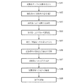
次に、本実施形態による腐食試験方法について図1乃至図3を用いて説明する。 Next, the corrosion test method according to the present embodiment will be described with reference to FIGS.
まず、試験水タンク32内に、試験水である電解質の水溶液を注入する(ステップS11)。試験水タンク32内の試験水量は、水位センサ50によってモニタし、水位センサ50からのデータにもとにして必要に応じて補給する。
First, an electrolyte aqueous solution as test water is injected into the test water tank 32 (step S11). The amount of test water in the
試験水としては、例えば純水1000gにNaClを0.07g(1.2ミリmol/リットル)溶かしたNaCl水溶液を用いることができる。なお、降雨水中に含まれる電解質の量は、降雨時間の経過とともに変化し、降雨開始2h前後に最大値を示し、その後急激に減少することが知られている。上記試験水のNaCl濃度は、降雨水中に含まれる平均的なイオン濃度である0.3ミリmol/リットルの4倍であるが、試験槽10の調温/調湿室14で50℃/90%RH程度に調整した場合、平均的な大気腐食環境(=浮遊イオン量)になると推定される。
As test water, for example, a NaCl aqueous solution in which 0.07 g (1.2 mmol / liter) NaCl is dissolved in 1000 g of pure water can be used. It is known that the amount of electrolyte contained in the rainwater changes with the lapse of the rain time, shows a maximum value around 2 h after the start of the rain, and then rapidly decreases. The NaCl concentration of the test water is four times the average ion concentration of 0.3 millimol / liter contained in the rainwater, but is 50 ° C./90 in the temperature control /
試験水の電解質濃度を高めることにより(例えば、純水1000gにNaClを0.3g(5.0ミリmol/リットル)溶かしたNaCl水溶液を用いる)、大気腐食の加速試験を行うようにしてもよい。用いる電解質及びその濃度は、試験目的等に応じて適宜設定することが望ましい。 An accelerated test of atmospheric corrosion may be performed by increasing the electrolyte concentration of test water (for example, using a NaCl aqueous solution in which 0.3 g (5.0 mmol / liter) NaCl is dissolved in 1000 g of pure water). . The electrolyte to be used and its concentration are preferably set as appropriate according to the purpose of the test.
電解質としては、雨水をイオン分析したときに得られる陽イオンのNa+、Mg2+、NH4 +、K+、Ca2+、Li+と、陰イオンのCl−、SO4 2−、NO3 −、F−、NO2 −、Br−、PO4 3−の組み合わせである、NaCl、MgCl、KCl、MgSO4、NaNO3、Mg(NO3)2など、水に溶ける物質を適用することができる。特に、毒性が無く取り扱いが容易なNaClやMgClなどが望ましい。 As electrolytes, cations Na + , Mg 2+ , NH 4 + , K + , Ca 2+ , Li + obtained by ion analysis of rainwater and anions Cl − , SO 4 2− , NO 3 − are used. , F − , NO 2 − , Br − , PO 4 3− , NaCl, MgCl, KCl, MgSO 4 , NaNO 3 , Mg (NO 3 ) 2, and the like can be applied. . In particular, NaCl, MgCl, and the like that are non-toxic and easy to handle are desirable.
次いで、霧化器34の水位センサ52からのデータをもとに電磁弁38を開閉し、霧化器34内の試験水の量を調節する(ステップS12)。
Next, the
次いで、霧化器34内の試験水量が適正値になった後、霧化器34を作動して試験水を霧化する(ステップS13)。これにより、電解質を含む霧粒子を生成することができる。なお、霧化器34としては、水中で超音波振動を発振させる超音波法を用いた霧化器や、水を回転板上に滴下するディスクアトマイズ法を用いた霧化器を適用することができる。
Next, after the amount of test water in the
次いで、加熱器36を、例えば60℃程度の温度に加熱する。
Next, the
次いで、加熱器36の昇温を待ってから電磁弁40を開放し、霧化器34内の霧を加熱器36内に導入する。
Next, after waiting for the temperature of the
図3は電解質を含む霧粒子の加熱に伴う挙動を説明する図である。 FIG. 3 is a diagram for explaining the behavior associated with heating of fog particles containing an electrolyte.
霧化器34により霧化された霧粒子60の粒子径は、概ね3μm程度である。電解質としてNaClを用いた試験水の霧粒子60の中には、Na+イオンとCl−イオンとが含まれている(図3(a))。
The particle diameter of the
霧粒子60を含む室温25℃の空気を60℃程度に加熱すると、両温度間で空気の飽和水蒸気量が5.7倍に増加するため、霧粒子60を包む空気中の湿度は20%RH以下に低下する。この湿度低下と霧粒子60の昇温とが相俟って、霧粒子60からH2O分子が水蒸気62として蒸発する(図3(b))。
When air at room temperature of 25 ° C. including the
これにより、霧粒子60の粒子径は1μm以下のサイズまで小さくなる。すなわち、霧粒子60は水蒸気化し、電解質を含む水蒸気64となる(図3(c))。
Thereby, the particle diameter of the
こうして、霧化器34から導入された霧粒子は熱せられてH2O分子が蒸発し、粒子径は水蒸気レベルまで小さくなる(ステップS14)。
Thus, the mist particles introduced from the
霧粒子から蒸発した水蒸気62及び電解質を含む水蒸気64は、加熱器36に続く調温/調湿室14に導入される(ステップS15)。
The
試験水を霧化だけでなく水蒸気化しているのは、霧の状態で調温/調湿湿14に導入した場合、その自重によって下方の床面に降りていきやすくなり、一部が結露等するなどして、結果的に試験槽10に供給した電解質量と試験槽10内に浮遊する電解質量に大きな差が生じる虞があるからである。水蒸気化することで、試験槽10内に供給した電解質を、そのまま試験槽10内に浮遊させることができる。
The test water is not only atomized but also steamed. When it is introduced into the temperature / humidity /
次いで、調温/調湿室14において、乾球温度センサ20及び湿球温度センサ22により、調温/調湿室14内の温度及び相対湿度を測定する。そして、測定した温度及び相対湿度が設定値と異なる場合には、調温/調湿室14内の温度及び相対湿度が設定値となるように、除湿/冷却器16、加湿器17、加熱器18を適宜制御する。
Next, in the temperature control /
具体的には、調温/調湿室14内の温度及び湿度が設定値よりも低い場合には、除湿器(除湿/冷却器16)をオフ、加湿器をオンにして、調温/調湿室14内の湿度を上げる。また、加熱器18をオン、冷却器(除湿/冷却器16)をオフにして、調温/調湿室14内の温度を上げる。
Specifically, when the temperature and humidity in the temperature adjustment /
調温/調湿室14内の温度が設定値よりも低く湿度が設定値よりも高い場合には、除湿器(除湿/冷却器16)をオン、加湿器17をオフにして、調温/調湿室14内の湿度を下げる。また、加熱器18をオン、冷却器(除湿/冷却器16)をオフにして、調温/調湿室14内の温度を上げる。
When the temperature in the temperature control /
調温/調湿室14内の温度が設定値よりも高く湿度が設定値よりも低い場合には、除湿器(除湿/冷却器16)をオフ、加湿器17をオンにして、調温/調湿室14内の湿度を上げる。また、加熱器18をオフ、冷却器(除湿/冷却器16)をオンにして、調温/調湿室14内の温度を下げる。
When the temperature in the temperature adjustment /
調温/調湿室14内の温度及び湿度が設定値よりも高い場合には、除湿器(除湿/冷却器16)をオン、加湿器17をオフにして、調温/調湿室14内の湿度を下げる。また、加熱器18をオン、冷却器(除湿/冷却器16)をオフにして、調温/調湿室14内の温度を上げる。
When the temperature and humidity in the temperature /
このようにして、調温/調湿室14内の温度及び湿度が設定値に保たれるように、フィードバック制御を行う。これにより、調温/調湿室14から連続する試験槽10内の温度及び湿度は、所定の設定値に制御される(ステップS16)。
In this way, feedback control is performed so that the temperature and humidity in the temperature /
このようにして、試験槽10内に、温度及び湿度が設定値に保たれ、水蒸気62及び電解質を含む水蒸気64が存在する試験環境が形成される。すなわち、試験槽10内には、表面吸着水と大気中に浮遊する塩(電解質)が共存する試験環境を実現することができる。
Thus, a test environment in which the temperature and humidity are maintained at the set values and the
大気浮遊塩は、高湿環境下で生じる表面吸着水に溶解して金属を腐食する。このときの表面吸着水中の電解質濃度は、降雨水中に含まれる電解質の濃度に近似すると推定される。すなわち、大気浮遊塩は、降雨の開始とともに雨滴に接触して取り込まれるが、このときに大気浮遊塩が雨滴に溶け込む挙動が、大気浮遊塩が表面吸着水に溶け込むメカニズムと同等であるからである。したがって、電解質を含む水蒸気64が存在する試験槽10内の試験環境は、大気腐食を評価するための環境として有用である。
Airborne salts dissolve in surface adsorbed water generated in a high humidity environment and corrode metals. The electrolyte concentration in the surface adsorbed water at this time is estimated to approximate the concentration of the electrolyte contained in the rainwater. That is, airborne salt is taken in contact with raindrops at the start of rainfall, but the behavior of airborne salt dissolving in raindrops at this time is equivalent to the mechanism in which airborne salt dissolves in surface adsorbed water. . Therefore, the test environment in the
次いで、試験環境が形成された試験槽10内に、評価対象の試料を設置する(ステップS17)。
Next, the sample to be evaluated is placed in the
次いで、試料を所定の時間、試験槽10内の試験環境に暴露する(ステップS18)。
Next, the sample is exposed to the test environment in the
次いで、所定の時間、試験環境に暴露した試料を取り出し、表面観察などの評価を行う(ステップS19)。 Next, a sample exposed to the test environment for a predetermined time is taken out and evaluation such as surface observation is performed (step S19).
上記試験水を用い、試験槽10内に、温度49℃、相対湿度80%RHの試験環境を作り、無電界Niめっき皮膜を形成した金属板を放置した。2000h後に取り出して表面観察したところ、無電界Niめっき皮膜に腐食生成物が生じていた。
Using the above test water, a test environment having a temperature of 49 ° C. and a relative humidity of 80% RH was created in the
一方、従来の恒温恒湿槽を用いて、温度49℃、相対湿度80%RHの試験環境を作り、無電界Niめっき皮膜を形成した金属板を放置した。2000h後に取り出して表面観察したところ、無電界Niめっき皮膜に腐食生成物は生じていなかった。 On the other hand, using a conventional constant temperature and humidity chamber, a test environment having a temperature of 49 ° C. and a relative humidity of 80% RH was created, and the metal plate on which the electroless Ni plating film was formed was left. When taken out after 2000 hours and observed on the surface, no corrosion product was generated in the electroless Ni plating film.
以上の結果から、本実施形態による腐食試験装置により形成される試験環境は、電解質の影響を反映した大気環境に相当するものであることが判った。したがって、この腐食試験装置を用いた信頼性評価は、公衆電話ボックスや無人の電気通信用建屋などの直接外気の影響を受ける場所で使用する電子機器等では、大気腐食に対する長期的な信頼性を評価するうえで有用である。 From the above results, it was found that the test environment formed by the corrosion test apparatus according to the present embodiment corresponds to the atmospheric environment reflecting the influence of the electrolyte. Therefore, the reliability evaluation using this corrosion test equipment has long-term reliability against atmospheric corrosion in electronic equipment used in places affected by direct outside air such as public telephone boxes and unmanned telecommunication buildings. Useful for evaluation.
このように、本実施形態によれば、電解質の水溶液を霧化して電解質を含む霧粒子を生成し、電解質を含む霧粒子を加熱して電解質を含む水蒸気を生成することにより、試験環境を形成するので、実際の大気と同様の、表面吸着水と大気浮遊塩とが共存する試験環境を容易に実現することができる。これにより、大気腐食環境を十分に反映した腐食試験を行うことができる。 Thus, according to the present embodiment, a test environment is formed by atomizing an aqueous solution of an electrolyte to generate fog particles containing the electrolyte, and heating the fog particles containing the electrolyte to generate water vapor containing the electrolyte. Therefore, it is possible to easily realize a test environment in which surface adsorbed water and atmospheric suspended salt coexist as in the actual atmosphere. As a result, a corrosion test that sufficiently reflects the atmospheric corrosion environment can be performed.
[第2実施形態]
本発明の第2実施形態による腐食試験方法及び装置について図4及び図5を用いて説明する。なお、図1乃至図3に示す第1実施形態による腐食試験方法及び装置と同様の構成要素には同一の符号を付し、説明を省略し或いは簡潔にする。
[Second Embodiment]
A corrosion test method and apparatus according to a second embodiment of the present invention will be described with reference to FIGS. Components similar to those of the corrosion test method and apparatus according to the first embodiment shown in FIGS. 1 to 3 are denoted by the same reference numerals, and description thereof is omitted or simplified.
図4は本実施形態による腐食試験方法及び装置の原理を説明するグラフ、図5は本実施形態による腐食試験装置の構造を示す概略図である。 FIG. 4 is a graph for explaining the principle of the corrosion test method and apparatus according to the present embodiment, and FIG. 5 is a schematic diagram showing the structure of the corrosion test apparatus according to the present embodiment.
第1実施形態による腐食試験方法では、装置の外部に設置した試験水タンク32から霧化器34に供給される試験水を一旦霧化し、次にその霧粒子を60℃に昇温して水蒸気へと状態変化した後に試験槽10内へ導入している。ここで、試験水の霧粒子が水の沸点である100℃よりも大幅に低い温度(〜60℃)で水蒸気へと状態変化するのは、霧粒子が内在している空気が昇温に伴って、その飽和水蒸気量が大きく増加したためと推定される。
In the corrosion test method according to the first embodiment, test water supplied to the
しかしながら、60℃の水蒸気を、例えばJIS K 2246やJIS K 5600−7−2などに規定される試験方法と同様の50℃に設定した試験槽10内に導入する場合を考えると、50℃における飽和水蒸気量は60℃の飽和水蒸気量の2/3程度であり大きく減少することから、50℃への温度降下によって水蒸気が肥大化して霧粒子に状態変化することが考えられる。この結果、試験槽10内で目標とする試験環境を構築することができず、所望の試験を行うことができなくなる虞がある。
However, considering the case where water vapor at 60 ° C. is introduced into the
また、試験水タンク32から霧化器34に供給される試験水は、霧化の過程で超音波振動によって昇温することから、生成した霧粒子が内在する空気の温度も上昇することになる。50℃の水蒸気を生成しようとする場合、霧粒子が内在する空気の温度上昇は、昇温に伴って増加する飽和水蒸気量の増加分を低下させることとなり、水蒸気への状態変化を妨げる虞がある。
Further, since the temperature of the test water supplied from the
本実施形態では、水蒸気化した試験水が霧粒子に状態変化するのを防止して適切な試験環境を構築しうる腐食試験方法及び装置を示す。 In the present embodiment, a corrosion test method and apparatus capable of preventing the state of vaporized test water from changing to mist particles and constructing an appropriate test environment will be described.
図4は本実施形態による腐食試験方法の原理を説明するグラフである。 FIG. 4 is a graph illustrating the principle of the corrosion test method according to the present embodiment.
図4に示すように、室温状態(25℃)における飽和水蒸気量は、約23.0[g/m3]である。室温状態における霧粒子が内在する空気の湿度は、霧化器34で生じた霧粒子によって、当初の50%RHから95%RH以上まで上昇する。室温状態の霧粒子が内在する空気の湿度が95%RHであるとすると、霧粒子が内在する空気中の水蒸気量は、約21.9[g/m3]となる。一方、60℃における飽和水蒸気量は、約130[g/m3]である。したがって、室温状態の霧粒子を60℃に昇温すると、飽和水蒸気量は5.7倍程度に増加し、結果的に60℃における相対湿度が16.8%程度に低下して、霧粒子が水蒸気へと状態変化する。
As shown in FIG. 4, the saturated water vapor amount at room temperature (25 ° C.) is about 23.0 [g / m 3 ]. The humidity of the air containing the fog particles in the room temperature state is increased from the initial 50% RH to 95% RH or more by the fog particles generated in the
以上の結果を考慮すると、50℃への昇温に伴う飽和水蒸気量の増加が少なくとも5.7倍程度あれば、霧化器34により霧化した霧粒子を安定して水蒸気へと状態変化させることができるものと考えられる。
Considering the above results, if the increase in the amount of saturated water vapor accompanying the temperature rise to 50 ° C. is at least about 5.7 times, the state of the atomized mist particles atomized by the
50℃における飽和水蒸気量は、図4に示すように、約82.8[g/m3]である。霧粒子を50℃に昇温することに伴って霧粒子が内在する空気中の飽和水蒸気量が5.7倍に増加するためには、昇温前の飽和水蒸気量が約14.5[g/m3]であることが必要である。この条件を満たす空気の温度は、図4に示すように、約17℃である。 The saturated water vapor amount at 50 ° C. is about 82.8 [g / m 3 ] as shown in FIG. In order to increase the amount of saturated water vapor in the air containing mist particles by 5.7 times as the temperature of the mist particles is increased to 50 ° C., the amount of saturated water vapor before the temperature increase is about 14.5 [g. / M 3 ]. The temperature of the air that satisfies this condition is about 17 ° C. as shown in FIG.
すなわち、霧粒子が内在する17℃の空気を50℃に昇温することで、飽和水蒸気量が5.7倍程度に増加し、結果的に50℃における相対湿度が17.5%以下に低下して、霧粒子を水蒸気へと状態変化させることができる。 That is, by raising the temperature of 17 ° C. air containing mist particles to 50 ° C., the amount of saturated water vapor increases to about 5.7 times, and as a result, the relative humidity at 50 ° C. decreases to 17.5% or less. Thus, the state of the fog particles can be changed to water vapor.
なお、上記の説明では、霧粒子が内在する空気を60℃に昇温した場合の実験例に基づき、昇温に伴う飽和水蒸気量の増加を5.7倍と仮定したが、昇温に伴う飽和水蒸気の増加が3.6倍程度以上であれば、50℃で電解質を含む水蒸気を得ることができる。 In the above description, it is assumed that the increase in the amount of saturated water vapor accompanying the temperature increase is 5.7 times based on the experimental example in which the air in which the fog particles are contained is heated to 60 ° C. If the increase in saturated water vapor is about 3.6 times or more, water vapor containing an electrolyte can be obtained at 50 ° C.
この条件を満たすような霧粒子が内在する空気を得る手段としては、霧化する試験水の温度を下げる方法がある。試験水の温度を下げると、低温の霧粒子が空気中に内在することとなり、結果的に、霧粒子が内在する空気の温度を下げることができる。また、霧化器34内部の試験水を温度制御することで、霧化時の超音波振動の印加に伴う液温上昇を防止することができ、霧粒子から水蒸気への状態変化を安定化させることができる。
As a means for obtaining air containing mist particles that satisfy this condition, there is a method of lowering the temperature of the test water to be atomized. When the temperature of the test water is lowered, low-temperature mist particles are present in the air, and as a result, the temperature of the air in which the mist particles are present can be lowered. In addition, by controlling the temperature of the test water inside the
図5は、本実施形態による腐食試験装置の構造を示す概略図である。図5は、図1に示す腐食試験装置において、本実施形態による腐食試験装置に特徴的な霧化器34及び加熱器36の部分のみを抜き出したものである。図5では、霧化器34と加熱器36との間の電磁弁40は記載を省略している。他の構成部分については、図1に示す第1実施形態による腐食試験装置と同様である。
FIG. 5 is a schematic view showing the structure of the corrosion test apparatus according to the present embodiment. FIG. 5 shows only the portions of the
霧化器34内には、試験水タンク32から送られた試験水を霧化のために一時的に貯蔵する試験水槽70が設けられている。試験水槽70内には、試験水の温度を測定する温度計72と、試験水の温度を制御する温度調節器74とが設けられている。また、霧化器34には、生成した霧粒子を内在する空気の温度を測定する温度計76が設けられている。温度計72,76及び温度調節器74には、図示しない制御装置が接続されており、霧粒子が内在する空気の温度に応じて試験水槽70内の試験水の温度を制御できるようになっている。
In the
加熱器36は、霧化器34により生成された霧を内在する空気を伝搬する石英ガラス管80と、石英ガラス管80内を伝搬する霧が内在する空気を昇温するためのヒータ82とを有している。ヒータ82には、ヒータ82の温度を制御する温度調節器84が設けられている。石英ガラス管80の出口部分には、ヒータ82により昇温されて水蒸気化した試験水の温度を測定する温度計86が設けられている。温度計86及び温度調節器84には、図示しない制御装置が接続されており、石英ガラス管80から放出された水蒸気の温度に応じてヒータ82の温度を制御できるようになっている。
The
次に、本実施形態による腐食試験方法について図1、図2及び図5を用いて説明する。 Next, the corrosion test method according to the present embodiment will be described with reference to FIGS.
まず、試験水タンク32内に、試験水である電解質の水溶液を注入する(ステップS11)。 First, an electrolyte aqueous solution as test water is injected into the test water tank 32 (step S11).
次いで、霧化器34の水位センサ52からのデータをもとに電磁弁38を開閉し、霧化器34内の試験水の量を調節する(ステップS12)。
Next, the
次いで、霧化器34内の試験水量が適正値になった後、霧化器34を作動して試験水を霧化する(ステップS13)。これにより、電解質を含む霧粒子を生成することができる。
Next, after the amount of test water in the
この際、霧化器34の試験水槽70内の試験水が霧化の過程での超音波振動によって昇温することを防止するために、温度調節器74によって試験水槽70内の試験水の温度を所定値に制御する。超音波式の霧化器では、良好な霧化を実現するために、試験水の水位を最適な状態に維持することが重要である。かかる観点から、試験水の水位に影響を及ぼさない温度調節器74として、図示するような熱媒体をパイプ内に循環させる液体循環式温度調節器が好ましい。
At this time, the temperature of the test water in the
次いで、霧化器34により生成された霧粒子が内在する空気の温度を、温度計76により測定する。測定した空気の温度が所定の温度からずれている場合には、図示しない制御装置を介して温度調節器74により試験水槽内の試験水の温度を制御し、霧化器34により生成される霧粒子が内在する空気の温度を所定値に調節する。
Next, the temperature of the air containing the fog particles generated by the
ここでは、霧化器34により生成された霧粒子が内在する空気の温度が、例えば17℃になるように、温度調節器74を制御するものとする。
Here, it is assumed that the
次いで、霧化器34により生成された霧粒子が内在する空気を、加熱器36に導入する。加熱器36内に導入された空気中の霧粒子は、石英ガラス管80を伝搬する過程でヒータ82により昇温され、水蒸気化する(ステップS14)。
Next, the air containing the mist particles generated by the
次いで、加熱器36から放出される水蒸気の温度を、温度計86により測定する。温度計86により測定した水蒸気の温度が所定値からずれている場合には、図示しない制御装置を介して温度調節器84によりヒータ82を制御し、加熱器36から放出される水蒸気の温度を所定値に調節する。
Next, the temperature of the water vapor discharged from the
ここでは、加熱器36から放出される水蒸気の温度が、JISの試験方法に用いられる温度である50℃になるように、温度調節器を制御するものとする。霧粒子が内在する17℃の空気を50℃に昇温することで、飽和水蒸気量が5.7倍程度に増加し、結果的に50℃における相対湿度が17.5%以下に低下して、霧粒子を水蒸気へと状態変化させることができる。
Here, the temperature controller is controlled so that the temperature of the water vapor discharged from the
なお、加熱器36から放出される水蒸気の温度が、試験槽10内の温度以下、例えば50℃以下になるように制御すれば、試験槽10内に導入した水蒸気が霧粒子に状態変化するのを防止することができる。
If the temperature of the water vapor discharged from the
次いで、加熱器36により生成した水蒸気を、調温/調湿室14により温度及び湿度が設定値に保たれた試験槽10内に導入する。
Next, the water vapor generated by the
この際、加熱器36により生成した50℃の水蒸気を、例えばJIS K 2246やJIS K 5600−7−2などのJISの試験方法と同様の50℃設定の試験槽10内に導入しても、状態変化することはなく、試験槽10内で目標とする試験環境を構築することができる。
At this time, even if the 50 ° C. water vapor generated by the
この後、ステップS16〜S19に示す第1実施形態による腐食試験方法と同様にして、試料の評価を行う。 Thereafter, the sample is evaluated in the same manner as the corrosion test method according to the first embodiment shown in steps S16 to S19.
次に、本実施形態による腐食試験装置を用いて実際に水蒸気を生成した結果について説明する。 Next, the result of actually generating water vapor using the corrosion test apparatus according to the present embodiment will be described.
図5に示すように、液体循環式の温度調節器74を有する超音波型の霧化器34と、ヒータ82付きの石英ガラス管80を有する加熱器36とを組み合わせ、試験水の温度を12〜32℃の範囲で変化し、石英ガラス管80出口の気体の温度が50℃になるように、ヒータ82の温度を調整した。そして、石英ガラス管80の出口から放出された気体の状態を調べるために、石英ガラス管80の出口から放出された気体を暗室に導入して白色光を照射し、気体が霧粒子を含むか否かを判定した。
As shown in FIG. 5, an
この結果を、表1にまとめる。 The results are summarized in Table 1.

以上のことから、50℃に昇温した気体が水蒸気の状態であるためには、試験水の温度T1或いは昇温前における霧粒子が内在する空気の温度T2を25℃以下に設定する必要があることが判る。 From the above, in order for the gas heated to 50 ° C. to be in the state of water vapor, the temperature T 1 of the test water or the temperature T 2 of the air containing the fog particles before the temperature increase is set to 25 ° C. or lower. It turns out that it is necessary.
この結果を、50℃における飽和水蒸気量(82.8g/m3)と、霧粒子が内在する空気の温度における飽和水蒸気量との比から考察すると、昇温による飽和水蒸気量の増加量を3.6倍以上にすることにより、50℃で電解質を含む水蒸気が得られることが判る(表1参照)。 Considering this result from the ratio of the saturated water vapor amount at 50 ° C. (82.8 g / m 3 ) and the saturated water vapor amount at the temperature of the air in which the fog particles are present, the increase in the saturated water vapor amount due to the temperature rise is 3 It turns out that the water vapor | steam containing an electrolyte is obtained at 50 degreeC by making it 6 times or more (refer Table 1).
このように、本実施形態によれば、試験槽10内の試験環境に応じて、電解質を含む水蒸気を安定して供給することができる。これにより、表面吸着水と電解質が共存する大気腐食環境を、例えばJISの湿潤試験と同じ温湿度条件で、安定して構築することができる。
Thus, according to the present embodiment, the water vapor containing the electrolyte can be stably supplied according to the test environment in the
[変形実施形態]
本発明は上記実施形態に限らず種々の変形が可能である。
[Modified Embodiment]
The present invention is not limited to the above embodiment, and various modifications can be made.
例えば、上記実施形態では、電解質としてNaClを用いたが、MgClその他の電解質を用いてもよい。 For example, in the above embodiment, NaCl is used as the electrolyte, but MgCl or other electrolytes may be used.
また、上記実施形態では、1.2ミリmol/リットルの濃度のNaCl水溶液を試験水として用いたが、より高濃度の水溶液を用いて加速試験を行ってもよい。 Moreover, in the said embodiment, although the NaCl aqueous solution of 1.2 millimol / liter density | concentration was used as test water, you may perform an acceleration test using higher concentration aqueous solution.
また、上記第2実施形態では、JISの試験方法を考慮して、試験槽10内に導入する水蒸気の温度を50℃としたが、水蒸気の温度は50℃に限定されるものではない。水蒸気の温度は、試験槽10内の試験環境の温度に応じて適宜設定することができる。この場合、試験環境の温度における飽和水蒸気量が、試験水の霧粒子が内在する空気の昇温前の温度における飽和水蒸気量に対して3.6倍以上になるように、試験水や加熱器36の温度を制御すればよい。
In the second embodiment, in consideration of the JIS test method, the temperature of the water vapor introduced into the
以上詳述した通り、本発明の特徴をまとめると以下の通りとなる。 As detailed above, the characteristics of the present invention are summarized as follows.
(付記1) 電解質の水溶液を霧化して前記電解質を含む霧粒子を生成し、
前記電解質を含む霧粒子を加熱して前記電解質を含む水蒸気を生成し、
前記電解質を含む水蒸気に試験試料を暴露し、前記試験試料の耐腐食性を評価する
ことを特徴とする腐食試験方法。
(Appendix 1) An aqueous solution of the electrolyte is atomized to produce fog particles containing the electrolyte,
Heating the fog particles containing the electrolyte to produce water vapor containing the electrolyte,
A corrosion test method comprising: exposing a test sample to water vapor containing the electrolyte, and evaluating the corrosion resistance of the test sample.
(付記2) 付記1記載の腐食試験方法において、
前記試験試料を温度及び湿度が一定の試験槽内に設置し、前記電解質を含む前記水蒸気を前記試験槽内に導入する
ことを特徴とする腐食試験方法。
(Appendix 2) In the corrosion test method described in Appendix 1,
A corrosion test method, wherein the test sample is placed in a test tank having a constant temperature and humidity, and the water vapor containing the electrolyte is introduced into the test tank.
(付記3) 付記2記載の腐食試験方法において、
前記試験槽内の温度は、50±1℃であり、
前記試験層内の相対湿度は、95%以上である
ことを特徴とする腐食試験方法。
(Appendix 3) In the corrosion test method described in Appendix 2,
The temperature in the test chamber is 50 ± 1 ° C.,
The corrosion test method, wherein the relative humidity in the test layer is 95% or more.
(付記4) 付記1乃至3のいずれか1項に記載の腐食試験方法において、
前記電解質の水溶液の温度を25℃以下に制御する
ことを特徴とする腐食試験方法。
(Appendix 4) In the corrosion test method according to any one of appendices 1 to 3,
A corrosion test method, wherein the temperature of the electrolyte aqueous solution is controlled to 25 ° C. or lower.
(付記5) 付記1乃至4のいずれか1項に記載の腐食試験方法において、
前記電解質を含む水蒸気の温度における飽和水蒸気量が、前記電解質を含む霧粒子が内在する空気の加熱前の温度における飽和水蒸気量の3.6倍以上になるように、前記電解質の水溶液の温度を制御する
ことを特徴とする腐食試験方法。
(Appendix 5) In the corrosion test method according to any one of appendices 1 to 4,
The temperature of the aqueous solution of the electrolyte is adjusted so that the saturated water vapor amount at the temperature of the water vapor containing the electrolyte is at least 3.6 times the saturated water vapor amount at the temperature before heating of the air in which the fog particles containing the electrolyte are present. A corrosion test method characterized by control.
(付記6) 付記4又は5記載の腐食試験方法において、
液体循環式の温度調節器により、温度前記電解質の水溶液の温度を制御する
ことを特徴とする腐食試験方法。
(Appendix 6) In the corrosion test method described in Appendix 4 or 5,
A corrosion test method, characterized in that the temperature of the aqueous electrolyte solution is controlled by a liquid circulation temperature controller.
(付記7) 付記1乃至6のいずれか1項に記載の腐食試験方法において、
前記電解質を含む水蒸気の温度が50℃以下になるように、前記電解質を含む霧粒子を加熱する際の温度を制御する
ことを特徴とする腐食試験方法。
(Appendix 7) In the corrosion test method according to any one of appendices 1 to 6,
A corrosion test method, wherein the temperature at which the fog particles containing the electrolyte are heated is controlled so that the temperature of the water vapor containing the electrolyte is 50 ° C. or lower.
(付記8) 付記1乃至7のいずれか1項に記載の腐食試験方法において、
前記電解質は、NaClである
ことを特徴とする腐食試験方法。
(Appendix 8) In the corrosion test method according to any one of appendices 1 to 7,
The corrosion test method, wherein the electrolyte is NaCl.
(付記9) 付記1乃至8のいずれか1項に記載の腐食試験方法において、
前記電解質を含む霧粒子の粒径が1μm以下になるように、前記電解質を含む霧粒子を加熱する
ことを特徴とする腐食試験方法。
(Appendix 9) In the corrosion test method according to any one of appendices 1 to 8,
The corrosion test method, wherein the fog particles containing the electrolyte are heated so that the particle diameter of the fog particles containing the electrolyte is 1 μm or less.
(付記10) 付記1乃至9のいずれか1項に記載の腐食試験方法において、
前記電解質の水溶液は、超音波法又はディスクアトマイズ法により霧化する
ことを特徴とする腐食試験方法。
(Supplementary note 10) In the corrosion test method according to any one of supplementary notes 1 to 9,
The corrosion test method, wherein the aqueous electrolyte solution is atomized by an ultrasonic method or a disk atomization method.
(付記11) 試験試料を設置する試験槽と、
電解質の水溶液を霧化して前記電解質を含む霧粒子を生成する霧化器と、
前記電解質を含む霧粒子を加熱して前記電解質を含む水蒸気を生成し、前記試験槽に導入する加熱器と
を有することを特徴とする腐食試験装置。
(Supplementary note 11) a test tank in which a test sample is installed;
An atomizer that atomizes an aqueous solution of the electrolyte to generate mist particles containing the electrolyte; and
A corrosion test apparatus comprising: a heater that heats fog particles including the electrolyte to generate water vapor including the electrolyte and introduces the water vapor into the test tank.
(付記12) 付記11記載の腐食試験装置において、
前記霧化器は、前記電解質の水溶液の温度を制御する温度調節器を有する
ことを特徴とする腐食試験装置。
(Appendix 12) In the corrosion test apparatus according to Appendix 11,
The said atomizer has a temperature regulator which controls the temperature of the aqueous solution of the said electrolyte. The corrosion test apparatus characterized by the above-mentioned.
(付記13) 付記12記載の腐食試験装置において、
前記温度調節器は、液体循環式の温度調節器である
ことを特徴とする腐食試験装置。
(Supplementary note 13) In the corrosion test apparatus according to
The corrosion test apparatus, wherein the temperature controller is a liquid circulation type temperature controller.
(付記14) 付記12又は13記載の腐食試験装置において、
前記温度調節器は、前記電解質の水溶液の温度を25℃以下に制御する
ことを特徴とする腐食試験装置。
(Supplementary Note 14) In the corrosion test apparatus according to
The said temperature regulator controls the temperature of the aqueous solution of the said electrolyte to 25 degrees C or less. The corrosion test apparatus characterized by the above-mentioned.
(付記15) 付記12乃至14のいずれか1項に記載の腐食試験装置において、
前記温度調節器は、前記電解質を含む水蒸気の温度における飽和水蒸気量が、前記電解質を含む霧粒子が内在する空気の加熱前の温度における飽和水蒸気量の3.6倍以上になるように、前記電解質の水溶液の温度を制御する
ことを特徴とする腐食試験装置。
(Appendix 15) In the corrosion test apparatus according to any one of
The temperature controller is configured so that a saturated water vapor amount at a temperature of the water vapor containing the electrolyte is 3.6 times or more a saturated water vapor amount at a temperature before heating the air in which the fog particles containing the electrolyte are present. A corrosion tester characterized by controlling the temperature of an aqueous electrolyte solution.
(付記16) 付記11乃至15のいずれか1項に記載の腐食試験装置において、
前記加熱器は、前記電解質を含む水蒸気の温度が50℃以下になるように、前記電解質を含む霧粒子を加熱する
ことを特徴とする腐食試験装置。
(Supplementary Note 16) In the corrosion test apparatus according to any one of Supplementary Notes 11 to 15,
The said heating device heats the fog particle | grains containing the said electrolyte so that the temperature of the water vapor | steam containing the said electrolyte may be 50 degrees C or less. The corrosion test apparatus characterized by the above-mentioned.
(付記17) 付記11乃至16のいずれか1項に記載の腐食試験装置において、
前記試験槽内の温度及び湿度を測定する測定装置と、
前記測定装置の測定結果に応じて前記試験槽内の温度及び湿度を一定に保つ制御装置と
を更に有することを特徴とする腐食試験装置。
(Appendix 17) In the corrosion test apparatus according to any one of appendices 11 to 16,
A measuring device for measuring the temperature and humidity in the test chamber;
A corrosion test apparatus further comprising: a control device that keeps the temperature and humidity in the test tank constant according to the measurement result of the measurement device.
(付記18) 付記11乃至17のいずれか1項に記載の腐食試験装置において、
前記試験槽は、前記試験試料を設置する第1の空間と、前記試験槽内の温度及び湿度を調整する第2の空間とを有する
ことを特徴とする腐食試験装置。
(Appendix 18) In the corrosion test apparatus according to any one of appendices 11 to 17,
The said test tank has a 1st space which installs the said test sample, and a 2nd space which adjusts the temperature and humidity in the said test tank. The corrosion test apparatus characterized by the above-mentioned.
(付記19) 電解質を含む水蒸気が存在する試験雰囲気の形成方法であって、
電解質の水溶液を霧化して前記電解質を含む霧粒子を生成し、
前記電解質を含む霧粒子を加熱して前記電解質を含む水蒸気を生成する
ことを特徴とする試験雰囲気の形成方法。
(Supplementary note 19) A method for forming a test atmosphere in which water vapor containing an electrolyte exists,
Atomizing an aqueous electrolyte solution to produce mist particles containing the electrolyte,
A method for forming a test atmosphere, wherein the fog particles containing the electrolyte are heated to generate water vapor containing the electrolyte.
(付記20) 電解質を含む水蒸気が存在する試験環境を形成する試験雰囲気形成装置であって、
電解質の水溶液を霧化して前記電解質を含む霧粒子を生成する霧化器と、
前記電解質を含む霧粒子を加熱して前記電解質を含む水蒸気を生成する加熱器と
を有することを特徴とする試験雰囲気形成装置。
(Supplementary note 20) A test atmosphere forming apparatus for forming a test environment in which water vapor containing an electrolyte exists,
An atomizer that atomizes an aqueous solution of the electrolyte to generate mist particles containing the electrolyte; and
A test atmosphere forming apparatus, comprising: a heater that heats fog particles containing the electrolyte to generate water vapor containing the electrolyte.
10…試験槽
12…断熱壁
14…調温/調湿室
16…除湿/冷却器
17…加湿器
18,36…加熱器
20…乾球温度センサ
22…湿球温度センサ
24…湿布
26…純水タンク
30…試験環境形成装置
32…試験水タンク
34…霧化器
38,40,46…電磁弁
42,44…ドレイン
48,50,52…水位センサ
60…霧粒子
62…水蒸気
64…電解質を含む水蒸気
70…試験水槽
72,76,86…温度計
74,84…温度調節器
80…石英ガラス管
82…ヒータ
DESCRIPTION OF
Claims (8)
前記電解質を含む霧粒子を加熱して前記電解質を含む水蒸気を生成し、
前記電解質を含む水蒸気に試験試料を暴露し、前記試験試料の耐腐食性を評価する
ことを特徴とする腐食試験方法。 Atomizing an aqueous electrolyte solution to produce mist particles containing the electrolyte,
Heating the fog particles containing the electrolyte to produce water vapor containing the electrolyte,
A corrosion test method comprising: exposing a test sample to water vapor containing the electrolyte, and evaluating the corrosion resistance of the test sample.
前記試験試料を温度及び湿度が一定の試験槽内に設置し、前記電解質を含む前記水蒸気を前記試験槽内に導入する
ことを特徴とする腐食試験方法。 The corrosion test method according to claim 1,
A corrosion test method, wherein the test sample is placed in a test tank having a constant temperature and humidity, and the water vapor containing the electrolyte is introduced into the test tank.
前記電解質を含む水蒸気の温度における飽和水蒸気量が、前記電解質を含む霧粒子が内在する空気の加熱前の温度における飽和水蒸気量の3.6倍以上になるように、前記電解質の水溶液の温度を制御する
ことを特徴とする腐食試験方法。 In the corrosion test method according to claim 1 or 2,
The temperature of the aqueous solution of the electrolyte is adjusted so that the saturated water vapor amount at the temperature of the water vapor containing the electrolyte is at least 3.6 times the saturated water vapor amount at the temperature before heating of the air in which the fog particles containing the electrolyte are present. A corrosion test method characterized by control.
電解質の水溶液を霧化して前記電解質を含む霧粒子を生成する霧化器と、
前記電解質を含む霧粒子を加熱して前記電解質を含む水蒸気を生成し、前記試験槽に導入する加熱器と
を有することを特徴とする腐食試験装置。 A test tank in which a test sample is placed;
An atomizer that atomizes an aqueous solution of the electrolyte to generate mist particles containing the electrolyte; and
A corrosion test apparatus comprising: a heater that heats fog particles including the electrolyte to generate water vapor including the electrolyte and introduces the water vapor into the test tank.
前記霧化器は、前記電解質の水溶液の温度を制御する温度調節器を有する
ことを特徴とする腐食試験装置。 The corrosion test apparatus according to claim 4,
The said atomizer has a temperature regulator which controls the temperature of the aqueous solution of the said electrolyte. The corrosion test apparatus characterized by the above-mentioned.
前記試験槽内の温度及び湿度を測定する測定装置と、
前記測定装置の測定結果に応じて前記試験槽内の温度及び湿度を一定に保つ制御装置と
を更に有することを特徴とする腐食試験装置。 The corrosion test apparatus according to claim 4 or 5,
A measuring device for measuring the temperature and humidity in the test chamber;
A corrosion test apparatus further comprising: a control device that keeps the temperature and humidity in the test tank constant according to the measurement result of the measurement device.
電解質の水溶液を霧化して前記電解質を含む霧粒子を生成し、
前記電解質を含む霧粒子を加熱して前記電解質を含む水蒸気を生成する
ことを特徴とする試験雰囲気の形成方法。 A method for forming a test atmosphere in which water vapor containing an electrolyte exists,
Atomizing an aqueous electrolyte solution to produce mist particles containing the electrolyte,
A method for forming a test atmosphere, wherein the fog particles containing the electrolyte are heated to generate water vapor containing the electrolyte.
電解質の水溶液を霧化して前記電解質を含む霧粒子を生成する霧化器と、
前記電解質を含む霧粒子を加熱して前記電解質を含む水蒸気を生成する加熱器と
を有することを特徴とする試験雰囲気形成装置。
A test atmosphere forming device for forming a test atmosphere in which water vapor containing an electrolyte exists,
An atomizer that atomizes an aqueous solution of the electrolyte to generate mist particles containing the electrolyte; and
A test atmosphere forming apparatus, comprising: a heater that heats fog particles containing the electrolyte to generate water vapor containing the electrolyte.
Priority Applications (1)
| Application Number | Priority Date | Filing Date | Title |
|---|---|---|---|
| JP2006340940A JP4731455B2 (en) | 2006-09-07 | 2006-12-19 | Corrosion test method and apparatus |
Applications Claiming Priority (3)
| Application Number | Priority Date | Filing Date | Title |
|---|---|---|---|
| JP2006242486 | 2006-09-07 | ||
| JP2006242486 | 2006-09-07 | ||
| JP2006340940A JP4731455B2 (en) | 2006-09-07 | 2006-12-19 | Corrosion test method and apparatus |
Publications (2)
| Publication Number | Publication Date |
|---|---|
| JP2008089564A JP2008089564A (en) | 2008-04-17 |
| JP4731455B2 true JP4731455B2 (en) | 2011-07-27 |
Family
ID=39373860
Family Applications (1)
| Application Number | Title | Priority Date | Filing Date |
|---|---|---|---|
| JP2006340940A Expired - Fee Related JP4731455B2 (en) | 2006-09-07 | 2006-12-19 | Corrosion test method and apparatus |
Country Status (1)
| Country | Link |
|---|---|
| JP (1) | JP4731455B2 (en) |
Families Citing this family (17)
| Publication number | Priority date | Publication date | Assignee | Title |
|---|---|---|---|---|
| JP2012083254A (en) * | 2010-10-13 | 2012-04-26 | Idemitsu Kosan Co Ltd | Deterioration degree evaluation method for lubricant |
| CN103154696B (en) * | 2010-10-18 | 2015-07-08 | 东莞市升微机电设备科技有限公司 | Low-pressure high-low temperature test box capable of controlling humidity |
| DE102011085267B4 (en) * | 2011-10-27 | 2013-05-23 | Schott Ag | Rapid test method for assessing the tendency of glass packaging to delaminate |
| JP5975351B2 (en) * | 2013-05-27 | 2016-08-23 | スガ試験機株式会社 | Corrosion promotion tester and corrosion promotion test method |
| CN105181563B (en) * | 2015-07-28 | 2018-04-27 | 航天材料及工艺研究所 | Environment-friendly type mist environment chamber |
| JP6341902B2 (en) * | 2015-12-02 | 2018-06-13 | エスペック株式会社 | Water resistance test equipment |
| KR101799463B1 (en) * | 2016-10-07 | 2017-11-20 | 국방과학연구소 | Salt water sprayingtest system |
| KR101973971B1 (en) * | 2017-10-17 | 2019-04-30 | 대원강업주식회사 | High temperature corrosion cycle test equipment for suspension parts |
| KR102352786B1 (en) * | 2018-09-28 | 2022-01-20 | 한국전력공사 | Soil environment complex corrosion accelerating test apparatus |
| CN109540734B (en) * | 2019-01-09 | 2023-11-24 | 重庆工业职业技术学院 | High-pressure adsorption/desorption test device and method for gas-containing coal with controllable moisture |
| CN111157440B (en) * | 2020-01-23 | 2024-12-03 | 北京市理化分析测试中心 | Aging test chamber and test method capable of integrating and collecting aging products of polymer materials |
| KR102265974B1 (en) * | 2020-12-04 | 2021-06-15 | 임진현 | Apparatus for salt water spray test with multi-type structure |
| CN113008678A (en) * | 2021-03-02 | 2021-06-22 | 浙江工业大学之江学院 | Corrosive environment tensile tester with control function |
| CN113588536A (en) * | 2021-08-31 | 2021-11-02 | 西安热工研究院有限公司 | Device and method for evaluating vapor phase corrosion inhibitor of thermal equipment |
| CN114199752B (en) * | 2021-12-15 | 2023-04-25 | 西南交通大学 | Bolt loosening test device for simulating corrosion environment and test method thereof |
| CN116148160B (en) * | 2022-12-15 | 2024-01-16 | 中国电器科学研究院股份有限公司 | Corrosion test device for simulating combined action of salt fog and polluted gas and use method |
| CN116124654B (en) * | 2022-12-26 | 2026-04-10 | 浙江理工大学 | An apparatus and method for testing the deposition characteristics of ammonium chloride particles |
Family Cites Families (18)
| Publication number | Priority date | Publication date | Assignee | Title |
|---|---|---|---|---|
| US3948804A (en) * | 1973-12-10 | 1976-04-06 | Universal Oil Products Company | Superactive acidic bimetallic catalytic composite and use thereof in conversion of hydrocarbons |
| JPS61155727A (en) * | 1984-12-27 | 1986-07-15 | Suga Shikenki Kk | Compound corrosion cycle tester |
| JPH0233988A (en) * | 1988-07-23 | 1990-02-05 | Seiko Epson Corp | semiconductor laser |
| JPH02110877A (en) * | 1988-10-18 | 1990-04-24 | Teac Corp | Disk device |
| JPH03267740A (en) * | 1990-03-16 | 1991-11-28 | Nissan Motor Co Ltd | Composite corrosion testing device |
| JPH05126414A (en) * | 1991-11-06 | 1993-05-21 | Hitachi Ltd | Refrigerator and apparatus for constant-temperature and constant-humidity |
| JPH0743314B2 (en) * | 1992-05-25 | 1995-05-15 | スガ試験機株式会社 | Test method for accelerating deterioration of coating film adhesion performance |
| JP2640211B2 (en) * | 1994-01-20 | 1997-08-13 | スガ試験機株式会社 | Humidity adjustment device for weather tester |
| JP4037918B2 (en) * | 1995-03-20 | 2008-01-23 | フマキラー株式会社 | Chemical spraying device |
| JPH10318910A (en) * | 1997-05-16 | 1998-12-04 | Nippon Telegr & Teleph Corp <Ntt> | Sodium chloride particle exposure evaluation device |
| JP3331547B2 (en) * | 2000-04-18 | 2002-10-07 | スガ試験機株式会社 | Deterioration acceleration test method |
| JP3188262B1 (en) * | 2001-01-18 | 2001-07-16 | スガ試験機株式会社 | Salt spray test equipment |
| JP3300928B1 (en) * | 2001-07-27 | 2002-07-08 | スガ試験機株式会社 | Salt spray test equipment |
| JP3973497B2 (en) * | 2002-06-27 | 2007-09-12 | 独立行政法人 日本原子力研究開発機構 | Load measurement test equipment |
| JP3834630B2 (en) * | 2002-10-09 | 2006-10-18 | 独立行政法人物質・材料研究機構 | Real environment simulated atmospheric corrosion test equipment |
| JP2006236821A (en) * | 2005-02-25 | 2006-09-07 | Ntn Corp | Pattern correction method and pattern correction device |
| JP2006258506A (en) * | 2005-03-15 | 2006-09-28 | National Institute For Materials Science | Real-environment simulated atmospheric corrosion test equipment and real-environment simulated atmospheric corrosion test method using the equipment |
| JP2007229189A (en) * | 2006-03-01 | 2007-09-13 | Hitachi Appliances Inc | Dishwasher |
-
2006
- 2006-12-19 JP JP2006340940A patent/JP4731455B2/en not_active Expired - Fee Related
Also Published As
| Publication number | Publication date |
|---|---|
| JP2008089564A (en) | 2008-04-17 |
Similar Documents
| Publication | Publication Date | Title |
|---|---|---|
| JP4731455B2 (en) | Corrosion test method and apparatus | |
| US5476636A (en) | Apparatus for performing weather resistance test | |
| CN107764723B (en) | Corrosion resistance test method of coating and application thereof | |
| Roventi et al. | Effect of carbonation process on the passivating products of zinc in Ca (OH) 2 saturated solution | |
| Prosek et al. | Application of automated electrical resistance sensors for measurement of corrosion rate of copper, bronze and iron in model indoor atmospheres containing short-chain volatile carboxylic acids | |
| KR20040039892A (en) | Apparatus for Testing Durability of Concrete Structure | |
| Rosati et al. | The impact of atmospheric oxidation on hygroscopicity and cloud droplet activation of inorganic sea spray aerosol | |
| JP3247576B2 (en) | Paint film durability evaluation device | |
| US2804870A (en) | Air furnace humidifier system | |
| JP2008128763A (en) | Corrosion test method | |
| Son et al. | Frost growth characteristics on vertical plates at ultra-low temperatures: frost separation phenomenon and surface treatment | |
| CN112563113B (en) | A heating and condensing device for improving the sensitivity of ICP-MS instruments | |
| CN115855750A (en) | A method for predicting the wetting state of the internal surface of electrical equipment | |
| JP2018096733A (en) | Method and device for testing accelerated weathering resistance | |
| JP2009174754A (en) | Air conditioner | |
| Niklasson et al. | Atmospheric corrosion of historical organ pipes: influence of acetic and formic acid vapour and water leaching on lead | |
| CN209372660U (en) | A kind of metal surface thin liquid film generating means | |
| JP6771769B2 (en) | Salt particle generator and corrosion acceleration tester | |
| JP2009069143A (en) | Method for evaluating weather resistance of metal material, metal material, and corrosion acceleration test apparatus for metal material | |
| CN111896460B (en) | Test device and test method for rapidly evaluating atmospheric wind stress corrosion | |
| Kitano et al. | Saturator efficiency and uncertainty of NMIJ two-pressure two-temperature humidity generator | |
| Badiea et al. | Effect of fluid velocity and temperature on the corrosion mechanism of low carbon steel in industrial water in the absence and presence of 2-hydrazino benzothiazole | |
| CN202869943U (en) | Ice accretion and rain freeze test equipment | |
| JP2640211B2 (en) | Humidity adjustment device for weather tester | |
| Konttinen et al. | Degradation of unglazed rough graphite-aluminium solar absorber surfaces in simulated acid and neutral rain |
Legal Events
| Date | Code | Title | Description |
|---|---|---|---|
| A621 | Written request for application examination |
Free format text: JAPANESE INTERMEDIATE CODE: A621 Effective date: 20090907 |
|
| A977 | Report on retrieval |
Free format text: JAPANESE INTERMEDIATE CODE: A971007 Effective date: 20110413 |
|
| TRDD | Decision of grant or rejection written | ||
| A01 | Written decision to grant a patent or to grant a registration (utility model) |
Free format text: JAPANESE INTERMEDIATE CODE: A01 Effective date: 20110419 |
|
| A01 | Written decision to grant a patent or to grant a registration (utility model) |
Free format text: JAPANESE INTERMEDIATE CODE: A01 |
|
| A61 | First payment of annual fees (during grant procedure) |
Free format text: JAPANESE INTERMEDIATE CODE: A61 Effective date: 20110419 |
|
| FPAY | Renewal fee payment (event date is renewal date of database) |
Free format text: PAYMENT UNTIL: 20140428 Year of fee payment: 3 |
|
| R150 | Certificate of patent or registration of utility model |
Free format text: JAPANESE INTERMEDIATE CODE: R150 |
|
| LAPS | Cancellation because of no payment of annual fees |