JP4732684B2 - Material transfer equipment - Google Patents
Material transfer equipment Download PDFInfo
- Publication number
- JP4732684B2 JP4732684B2 JP2003513624A JP2003513624A JP4732684B2 JP 4732684 B2 JP4732684 B2 JP 4732684B2 JP 2003513624 A JP2003513624 A JP 2003513624A JP 2003513624 A JP2003513624 A JP 2003513624A JP 4732684 B2 JP4732684 B2 JP 4732684B2
- Authority
- JP
- Japan
- Prior art keywords
- hollow needle
- container
- feeding
- medium
- outer end
- Prior art date
- Legal status (The legal status is an assumption and is not a legal conclusion. Google has not performed a legal analysis and makes no representation as to the accuracy of the status listed.)
- Expired - Lifetime
Links
- 239000000463 material Substances 0.000 title description 5
- 230000001681 protective effect Effects 0.000 claims abstract description 15
- 239000000126 substance Substances 0.000 claims abstract description 8
- 238000005452 bending Methods 0.000 claims description 10
- 239000011253 protective coating Substances 0.000 claims description 6
- 239000010409 thin film Substances 0.000 claims description 5
- 239000012528 membrane Substances 0.000 claims description 2
- 230000014759 maintenance of location Effects 0.000 claims 1
- 238000000034 method Methods 0.000 description 8
- 239000007924 injection Substances 0.000 description 5
- 238000002347 injection Methods 0.000 description 5
- 239000012530 fluid Substances 0.000 description 4
- 238000003780 insertion Methods 0.000 description 3
- 230000037431 insertion Effects 0.000 description 3
- 238000003825 pressing Methods 0.000 description 3
- 239000000654 additive Substances 0.000 description 2
- 230000000996 additive effect Effects 0.000 description 2
- 238000011109 contamination Methods 0.000 description 2
- 230000035515 penetration Effects 0.000 description 2
- 239000012190 activator Substances 0.000 description 1
- 239000003978 infusion fluid Substances 0.000 description 1
- 239000000203 mixture Substances 0.000 description 1
- 239000002245 particle Substances 0.000 description 1
Images


Classifications
-
- A—HUMAN NECESSITIES
- A61—MEDICAL OR VETERINARY SCIENCE; HYGIENE
- A61M—DEVICES FOR INTRODUCING MEDIA INTO, OR ONTO, THE BODY; DEVICES FOR TRANSDUCING BODY MEDIA OR FOR TAKING MEDIA FROM THE BODY; DEVICES FOR PRODUCING OR ENDING SLEEP OR STUPOR
- A61M5/00—Devices for bringing media into the body in a subcutaneous, intra-vascular or intramuscular way; Accessories therefor, e.g. filling or cleaning devices, arm-rests
- A61M5/178—Syringes
- A61M5/28—Syringe ampoules or carpules, i.e. ampoules or carpules provided with a needle
-
- A—HUMAN NECESSITIES
- A61—MEDICAL OR VETERINARY SCIENCE; HYGIENE
- A61J—CONTAINERS SPECIALLY ADAPTED FOR MEDICAL OR PHARMACEUTICAL PURPOSES; DEVICES OR METHODS SPECIALLY ADAPTED FOR BRINGING PHARMACEUTICAL PRODUCTS INTO PARTICULAR PHYSICAL OR ADMINISTERING FORMS; DEVICES FOR ADMINISTERING FOOD OR MEDICINES ORALLY; BABY COMFORTERS; DEVICES FOR RECEIVING SPITTLE
- A61J1/00—Containers specially adapted for medical or pharmaceutical purposes
- A61J1/14—Details; Accessories therefor
- A61J1/20—Arrangements for transferring or mixing fluids, e.g. from vial to syringe
- A61J1/2089—Containers or vials which are to be joined to each other in order to mix their contents
-
- A—HUMAN NECESSITIES
- A61—MEDICAL OR VETERINARY SCIENCE; HYGIENE
- A61M—DEVICES FOR INTRODUCING MEDIA INTO, OR ONTO, THE BODY; DEVICES FOR TRANSDUCING BODY MEDIA OR FOR TAKING MEDIA FROM THE BODY; DEVICES FOR PRODUCING OR ENDING SLEEP OR STUPOR
- A61M5/00—Devices for bringing media into the body in a subcutaneous, intra-vascular or intramuscular way; Accessories therefor, e.g. filling or cleaning devices, arm-rests
- A61M5/178—Syringes
- A61M5/24—Ampoule syringes, i.e. syringes with needle for use in combination with replaceable ampoules or carpules, e.g. automatic
-
- A—HUMAN NECESSITIES
- A61—MEDICAL OR VETERINARY SCIENCE; HYGIENE
- A61M—DEVICES FOR INTRODUCING MEDIA INTO, OR ONTO, THE BODY; DEVICES FOR TRANSDUCING BODY MEDIA OR FOR TAKING MEDIA FROM THE BODY; DEVICES FOR PRODUCING OR ENDING SLEEP OR STUPOR
- A61M5/00—Devices for bringing media into the body in a subcutaneous, intra-vascular or intramuscular way; Accessories therefor, e.g. filling or cleaning devices, arm-rests
- A61M5/178—Syringes
- A61M5/28—Syringe ampoules or carpules, i.e. ampoules or carpules provided with a needle
- A61M5/281—Syringe ampoules or carpules, i.e. ampoules or carpules provided with a needle using emptying means to expel or eject media, e.g. pistons, deformation of the ampoule, or telescoping of the ampoule
- A61M5/282—Syringe ampoules or carpules, i.e. ampoules or carpules provided with a needle using emptying means to expel or eject media, e.g. pistons, deformation of the ampoule, or telescoping of the ampoule by compression of deformable ampoule or carpule wall
-
- A—HUMAN NECESSITIES
- A61—MEDICAL OR VETERINARY SCIENCE; HYGIENE
- A61M—DEVICES FOR INTRODUCING MEDIA INTO, OR ONTO, THE BODY; DEVICES FOR TRANSDUCING BODY MEDIA OR FOR TAKING MEDIA FROM THE BODY; DEVICES FOR PRODUCING OR ENDING SLEEP OR STUPOR
- A61M5/00—Devices for bringing media into the body in a subcutaneous, intra-vascular or intramuscular way; Accessories therefor, e.g. filling or cleaning devices, arm-rests
- A61M5/178—Syringes
- A61M5/31—Details
- A61M5/32—Needles; Details of needles pertaining to their connection with syringe or hub; Accessories for bringing the needle into, or holding the needle on, the body; Devices for protection of needles
- A61M5/3205—Apparatus for removing or disposing of used needles or syringes, e.g. containers; Means for protection against accidental injuries from used needles
- A61M5/321—Means for protection against accidental injuries by used needles
- A61M5/3243—Means for protection against accidental injuries by used needles being axially-extensible, e.g. protective sleeves coaxially slidable on the syringe barrel
- A61M5/3275—Means for protection against accidental injuries by used needles being axially-extensible, e.g. protective sleeves coaxially slidable on the syringe barrel being connected to the needle hub or syringe by radially deflectable members, e.g. longitudinal slats, cords or bands
-
- A—HUMAN NECESSITIES
- A61—MEDICAL OR VETERINARY SCIENCE; HYGIENE
- A61J—CONTAINERS SPECIALLY ADAPTED FOR MEDICAL OR PHARMACEUTICAL PURPOSES; DEVICES OR METHODS SPECIALLY ADAPTED FOR BRINGING PHARMACEUTICAL PRODUCTS INTO PARTICULAR PHYSICAL OR ADMINISTERING FORMS; DEVICES FOR ADMINISTERING FOOD OR MEDICINES ORALLY; BABY COMFORTERS; DEVICES FOR RECEIVING SPITTLE
- A61J1/00—Containers specially adapted for medical or pharmaceutical purposes
- A61J1/05—Containers specially adapted for medical or pharmaceutical purposes for collecting, storing or administering blood, plasma or medical fluids ; Infusion or perfusion containers
- A61J1/06—Ampoules or carpules
- A61J1/067—Flexible ampoules, the contents of which are expelled by squeezing
-
- A—HUMAN NECESSITIES
- A61—MEDICAL OR VETERINARY SCIENCE; HYGIENE
- A61J—CONTAINERS SPECIALLY ADAPTED FOR MEDICAL OR PHARMACEUTICAL PURPOSES; DEVICES OR METHODS SPECIALLY ADAPTED FOR BRINGING PHARMACEUTICAL PRODUCTS INTO PARTICULAR PHYSICAL OR ADMINISTERING FORMS; DEVICES FOR ADMINISTERING FOOD OR MEDICINES ORALLY; BABY COMFORTERS; DEVICES FOR RECEIVING SPITTLE
- A61J1/00—Containers specially adapted for medical or pharmaceutical purposes
- A61J1/14—Details; Accessories therefor
- A61J1/20—Arrangements for transferring or mixing fluids, e.g. from vial to syringe
- A61J1/2003—Accessories used in combination with means for transfer or mixing of fluids, e.g. for activating fluid flow, separating fluids, filtering fluid or venting
- A61J1/2006—Piercing means
- A61J1/201—Piercing means having one piercing end
-
- A—HUMAN NECESSITIES
- A61—MEDICAL OR VETERINARY SCIENCE; HYGIENE
- A61J—CONTAINERS SPECIALLY ADAPTED FOR MEDICAL OR PHARMACEUTICAL PURPOSES; DEVICES OR METHODS SPECIALLY ADAPTED FOR BRINGING PHARMACEUTICAL PRODUCTS INTO PARTICULAR PHYSICAL OR ADMINISTERING FORMS; DEVICES FOR ADMINISTERING FOOD OR MEDICINES ORALLY; BABY COMFORTERS; DEVICES FOR RECEIVING SPITTLE
- A61J1/00—Containers specially adapted for medical or pharmaceutical purposes
- A61J1/14—Details; Accessories therefor
- A61J1/20—Arrangements for transferring or mixing fluids, e.g. from vial to syringe
- A61J1/2003—Accessories used in combination with means for transfer or mixing of fluids, e.g. for activating fluid flow, separating fluids, filtering fluid or venting
- A61J1/2006—Piercing means
- A61J1/2013—Piercing means having two piercing ends
-
- A—HUMAN NECESSITIES
- A61—MEDICAL OR VETERINARY SCIENCE; HYGIENE
- A61M—DEVICES FOR INTRODUCING MEDIA INTO, OR ONTO, THE BODY; DEVICES FOR TRANSDUCING BODY MEDIA OR FOR TAKING MEDIA FROM THE BODY; DEVICES FOR PRODUCING OR ENDING SLEEP OR STUPOR
- A61M5/00—Devices for bringing media into the body in a subcutaneous, intra-vascular or intramuscular way; Accessories therefor, e.g. filling or cleaning devices, arm-rests
- A61M5/178—Syringes
- A61M5/31—Details
- A61M5/32—Needles; Details of needles pertaining to their connection with syringe or hub; Accessories for bringing the needle into, or holding the needle on, the body; Devices for protection of needles
- A61M5/3205—Apparatus for removing or disposing of used needles or syringes, e.g. containers; Means for protection against accidental injuries from used needles
- A61M5/321—Means for protection against accidental injuries by used needles
- A61M5/3243—Means for protection against accidental injuries by used needles being axially-extensible, e.g. protective sleeves coaxially slidable on the syringe barrel
- A61M5/3245—Constructional features thereof, e.g. to improve manipulation or functioning
- A61M2005/3247—Means to impede repositioning of protection sleeve from needle covering to needle uncovering position
-
- A—HUMAN NECESSITIES
- A61—MEDICAL OR VETERINARY SCIENCE; HYGIENE
- A61M—DEVICES FOR INTRODUCING MEDIA INTO, OR ONTO, THE BODY; DEVICES FOR TRANSDUCING BODY MEDIA OR FOR TAKING MEDIA FROM THE BODY; DEVICES FOR PRODUCING OR ENDING SLEEP OR STUPOR
- A61M5/00—Devices for bringing media into the body in a subcutaneous, intra-vascular or intramuscular way; Accessories therefor, e.g. filling or cleaning devices, arm-rests
- A61M5/178—Syringes
- A61M5/31—Details
- A61M5/32—Needles; Details of needles pertaining to their connection with syringe or hub; Accessories for bringing the needle into, or holding the needle on, the body; Devices for protection of needles
- A61M5/3202—Devices for protection of the needle before use, e.g. caps
Landscapes
- Health & Medical Sciences (AREA)
- Life Sciences & Earth Sciences (AREA)
- Veterinary Medicine (AREA)
- Engineering & Computer Science (AREA)
- Public Health (AREA)
- General Health & Medical Sciences (AREA)
- Animal Behavior & Ethology (AREA)
- Heart & Thoracic Surgery (AREA)
- Hematology (AREA)
- Biomedical Technology (AREA)
- Anesthesiology (AREA)
- Vascular Medicine (AREA)
- Pharmacology & Pharmacy (AREA)
- Environmental & Geological Engineering (AREA)
- Infusion, Injection, And Reservoir Apparatuses (AREA)
- Medical Preparation Storing Or Oral Administration Devices (AREA)
- Feeding, Discharge, Calcimining, Fusing, And Gas-Generation Devices (AREA)
- Grinding Of Cylindrical And Plane Surfaces (AREA)
- Vending Machines For Individual Products (AREA)
- Electrical Discharge Machining, Electrochemical Machining, And Combined Machining (AREA)
- Push-Button Switches (AREA)
- Closures For Containers (AREA)
Abstract
Description
本発明は物質を送致するための装置に関する。本装置の主要な、しかし限定的ではない、適用では、媒質、とくに流体媒質の望む量を受取り手段に送致することである。好ましくは、送致される媒質は受取り手段に位置する流体にたとえば活性要素の混合物を導入する添加剤である。受取り手段は、追加的活性要素としての媒質を内容として含む注入液コンテナである。 The present invention relates to an apparatus for delivering a substance. The main but non-limiting application of the device is to deliver the desired amount of medium, in particular fluid medium, to the receiving means. Preferably, the medium to be delivered is an additive that introduces, for example, a mixture of active elements into the fluid located in the receiving means. The receiving means is an infusate container containing as a content a medium as an additional active element.
この目的のためには、従来、送致装置は、穿孔囲い又はたとえば注入液コンテナの受取り手段のプラグを刺し、その後で注射器を圧すことで媒質が受取り手段に注入される中空針を具備する注射器である。このプロセスでは、注射器を満たす準備作業ステップが必要になり、望む量の媒質を保管コンテナから注射器に移すか、または注射器は関連媒質の計測された量を含む小瓶から満たされる。これらの移動作業ステップは、一方で、中空針及び注射器の包装を解き、中空針を注射器に装填し、小瓶を開け又は刺して注射器を引き上げる必要があるために、時間消費的である。他方、これらの方法では、媒質の汚染という重大なリスクが存在する。 For this purpose, conventionally the delivery device is a syringe with a hollow needle into which the medium is injected into the receiving means by piercing the plug of the receiving means of the infusate container or the infusion solution container and then pressing the syringe. is there. This process requires a preparatory work step to fill the syringe, transferring the desired amount of medium from the storage container to the syringe or filling the syringe from a vial containing a measured amount of the associated medium. These mobile work step, on the other hand, unwrapped hollow needle and syringe, loaded with hollow needle to the syringe, because of the need to increase the opening of the vial or stabbing syringe is time consuming. On the other hand, these methods present a significant risk of media contamination.
本発明の目的は、比較的簡単で信頼できる方法で媒質の送致を可能にする装置を案出することである。 An object of the present invention is to devise an apparatus that enables the feeding of media in a relatively simple and reliable manner.
この目的は、請求項記載のように、適切な媒質を保持するコンテナ、前記媒質を送致するための中空針を有する閉鎖ユニット、前記閉鎖ユニットから突き出した外側端、及び前記中空針の前記外側端を被覆する活性状態から前記中空針からの媒質の送致のための使用非活性状態へと移動させることのできる安全装置、を具備する装置により達成される。 The purpose of the invention is to claim a container for holding a suitable medium, a closure unit having a hollow needle for feeding the medium, an outer end protruding from the closure unit, and the outer end of the hollow needle. This is achieved by a device comprising a safety device that can be moved from an active state that coats the tube to a non-active state for use in delivering media from the hollow needle.
本発明の請求項の仕様では、一体化された前記中空針と共に媒質を保持する送致コンテナ及び突き出した端、すなわち針の頭部を被覆する安全装置は組合わされて組合せユニットとなり、装置の送致コンテナでの送致プロセスの前に関連物資の望む量を準備することができる。針の頭部は安全装置により被覆されているので、装置は安全対策を施された中空針と共に送致プロセスのために容易にその状態で扱うことができる。媒質の移動及び送致プロセスのための注射器の準備の中間ステップは必ずしも必要ではない。望ましい簡易化、時間削減及び汚染に対する保護の向上はこのようにして達成される。 According to the specifications of the claims of the present invention, the feeding container for holding the medium together with the integrated hollow needle and the safety device covering the protruding end, i.e. the head of the needle, are combined into a combined unit, the feeding container of the device The desired amount of related materials can be prepared before the delivery process. Since the needle head is covered by a safety device, the device can easily be handled in that state for the feeding process with a hollow needle with safety measures. The intermediate step of preparing the syringe for the medium transfer and delivery process is not necessarily required. The desired simplification, time reduction and improved protection against contamination are thus achieved.
中空針の外側端が送致される媒質を保持する前記コンテナの穿孔囲いを刺すように設計されている場合は、前記安全装置は、前記送致コンテナから可動可能で中空針の前記突き出した端を覆う保護被覆を有し、前記囲いが刺されたときには、前記中空針の端の前進した保護位置から使用位置に接触により押し戻されることができて、前記中空針が前記囲いから引き抜かれたときには、再び前記保護位置に押し返されることができる。この実施態様では、扱いがとくに簡易化されている。 If the outer end of the hollow needle is designed to pierce the perforated enclosure of the container holding the medium to be fed, the safety device is movable from the feeding container and covers the protruding end of the hollow needle Having a protective covering, and when the enclosure is stabbed, it can be pushed back by contact from the advanced protection position of the end of the hollow needle to the use position, and when the hollow needle is pulled out of the enclosure again Can be pushed back to the protected position. In this embodiment, the handling is particularly simplified.
好ましくは、前記保護被覆は事前設定の切断点の方法により前記送致コンテナに連結され、前記保護被覆を前記送致コンテナから捻って引き離すための支点としての指把握ノブを具備する。 Preferably, the protective covering is connected to the feeding container by a preset cutting point method and comprises a finger grip knob as a fulcrum for twisting and pulling the protective covering away from the feeding container.
前記安全装置の安全本体は、前記閉鎖ユニットから突き出た中空針の部分で可動に案内される環状本体により形成される。環状本体は、保持力を生成する伸縮性保持手段により前記閉鎖ユニットに連結される。環状本体は、前記中空針の端を被覆する前進した保護位置で、保持手段の保持力により保持される。環状本体は、前記中空針に沿った保持力に対抗して使用位置に押し戻される。自由面上の前述の環状本体は、安全装置の前進ポイント上で他の部分に対して放射状に突き出ている環状拡大接触面を形成し、拡大した接触面により、結果として取外し開放においてコンテナの貫通可能ポイントと環状本体との接触を信頼できるものにする。 The safety body of the safety device is formed by an annular body that is movably guided by a hollow needle protruding from the closure unit. The annular body is connected to the closure unit by a stretchable holding means that generates a holding force. Annular body, the end of the hollow needle in the forward and the protective position covering is Riho lifting by the holding force of the holding means. The annular body is pushed back to the use position against the holding force along the hollow needle. The aforementioned annular body on the free surface forms an annular enlarged contact surface that projects radially to the other part on the advancement point of the safety device, and the enlarged contact surface results in penetration of the container at the removal opening Make the contact between the possible point and the annular body reliable.
前記保持手段は、継手により分割され、前記環状本体及び前記閉鎖ユニットに関節式に接続され、保護位置では前記中空針に平行に延び、使用位置では前記中空針から外へ拡がった位置に延びる支持部材を具備する。 The holding means is divided by a joint, is articulated to the annular body and the closure unit, extends in parallel to the hollow needle in the protective position, and extends to a position extending outward from the hollow needle in the use position A member is provided.
好ましくは、前記支持部材は前記閉鎖ユニットから前記環状本体に達する一つの部材に延び、曲げ継手によりほぼ半分の長さに分割される。このように実施すると、支持部材の材質の潜在的な柔軟性により、環状本体は、使用位置に押し戻された後に、自動的に少なくとも部分的には中空針の前端に対して前進することができ、従って環状本体は、単に若干自動的に保護位置に戻り、または装置使用後には単に若干さらに前進する。 Preferably, the support member extends from the closure unit to one member that reaches the annular body and is divided into approximately half lengths by a bending joint. When implemented in this way, due to the potential flexibility of the material of the support member, the annular body can automatically advance at least partially relative to the front end of the hollow needle after being pushed back into use. Thus, the annular body simply returns to the protected position slightly automatically, or simply advances further after use of the device.
とくに一つの有利な実施態様では、前記閉鎖ユニットは、前記支持部材を囲み、前記閉鎖ユニットから取外し可能で、前記保護位置に対応する位置に錠止めするために前記曲げ継手に向かって支持部材に沿って押し込むことができる嵌め込みリングを具備する。このようにして環状本体が保護的に中空針の外側端を囲む保護位置に安全装置が取外し可能に錠止めされるように嵌め込みリングが嵌め込まれる曲げ継手上の把握切込みができる。 In one particularly advantageous embodiment, the closure unit surrounds the support member, is removable from the closure unit and is secured to the support member towards the bending joint for locking in a position corresponding to the protected position. It has a fitting ring that can be pushed along. In this way, it is possible to make a grasp cut on the bending joint in which the fitting ring is fitted so that the safety device is removably locked in a protective position in which the annular body protects the outer end of the hollow needle.
送致コンテナは公知のボッテルパック(商標)プロセスを使って製造されたプラスチック・コンテナであることも可能である;すなわち挿入部分としての閉鎖ユニットは保護被覆により閉じる前に開放端に挿入される。 The feeding container can also be a plastic container manufactured using the known Bottelpack ™ process; that is, the closing unit as an insertion part is inserted into the open end before being closed by a protective covering.
中央部の挿入部分本体は、継続的にそれ自体に位置する中空針を含む;すなわち内部端は送致コンテナの内部に対して閉鎖ユニットから若干突き出している。中空針の直面内側端と送致コンテナ内に位置する媒質間の閉鎖ユニットを形成する挿入部分は、物質の圧力が増加し及び前記中空針により刺すことが可能なときに、前記中空針の端に対して押すことができるブロック部材を形成する薄膜を具備する。 The central insert body includes a hollow needle which is continuously located on its own; that is, the inner end projects slightly from the closure unit relative to the interior of the feeding container. Insert to form a closure unit between the medium located in the hollow needle facing inner ends with the up Reel container when enabling sting by increasing the pressure of material and the hollow needle, the end of the hollow needle A thin film is provided that forms a block member that can be pressed against.
媒質の圧力及び結果として生じる薄膜の圧力を高めるために、送致コンテナを圧縮することが可能である。 In order to increase the pressure of the medium and the resulting thin film, it is possible to compress the feeding container.
本発明を添付図面を参照して下記に説明する。 The present invention will be described below with reference to the accompanying drawings.
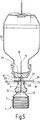
図において送致コンテナは全体として1の符号が付されている。公知のボッテルパック(商標)プロセスを使って製造されたアンプル類似のプラスティック・コンテナで、折り返しを伴い、蛇腹類似に作られ、図1から4、図5から7も参照、に示されたようなコンフィグレーションから送致コンテナ1を引き出すことができる。首部では、閉鎖ユニット3は挿入部分として送致コンテナ1に挿入される;幾つかのコンポーネントはプラスティックから成型される閉鎖ユニットの本体上に成型される。なかんずく安全装置17は、(送致装置使用前に)その部分は、図1及び3を参照するように、事前に設定された切断ポイント7で、送致コンテナ1上に成型された保護被覆5により保護されていて、事前に設定された切断ポイント7で保護被覆5を送致コンテナ1から捻って外すための手がかりとして使われる横に突き出た指把握グリップ9を有する。図3は図1及び2と同様の装置の操作状態を表しているが、保護被覆5は取外してある。
In the figure, the sending container is denoted by 1 as a whole. An ampoule-like plastic container manufactured using the well-known Bottelpak ™ process, made up like a bellows with folding, as shown in FIGS. 1 to 4, see also FIGS. 5 to 7 The sending
とくに図2及び3から明らかなことは、中央部の閉鎖ユニット3の本体は、中空針11により貫通されている;その内側端12は閉鎖ユニット3の本体に渡り若干内側に突き出ている。中空針11の内側端12と送致コンテナ1の内部の間には、閉鎖ユニット3の挿入部分の一部である薄膜13が存在する。
2 and 3 in particular, the body of the
中空針は、注射器中空針の長さとほぼ同じに対応する長さまで、閉鎖ユニット3の本体の外側端から延びている。図2,3、及び7は、外側に突き出た端15が被覆されている、すなわち保護位置にあり、全体として17の符号が付されている安全装置により保護されている操作状態を表している。
Hollow needle until length as the corresponding almost the same syringe hollow needle extends from the outer end of the body of the
安全装置17は閉鎖ユニット3の本体に一体として成型され、中空針11上で可動であり及び中空針のこの端、すなわち針の頭部を被覆するために中空針11の外側端15上の保護位置に配置されている環状本体19を具備する。環状本体19は、一体として成型されるロッド類似の形状の支持部材21により閉鎖ユニット3の本体と一ヶ所で連結し、環状本体19及び閉鎖ユニット3の本体への連結ポイントは曲げ継手により柔軟に保たれる。
環状本体は、保持力を生成する伸縮性保持手段により前記閉鎖ユニットに連結される。環状本体は、前記中空針の端を被覆する前進した保護位置で、保持手段の保持力により保持される。環状本体は、前記中空針に沿った保持力に対抗して使用位置に押し戻される。自由面上の前述の環状本体は、安全装置の前進ポイント上で他の部分に対して放射状に突き出ている環状拡大接触面を形成し、拡大した接触面により、結果として取外し開放においてコンテナの貫通可能ポイントと環状本体との接触を信頼できるものにする。さらに、支持部材21のほぼ半分の長さにわたり、支持部材21を分割する曲げ継手がある。図5,6を参照すると、環状本体19が中空針11に沿って保護位置から装置の使用位置に圧される場合は、曲げ継手23に接する支持部材21の部分は中空針11から広がり、図5に示されたように折り曲げられるように旋回する。
The
The annular body is connected to the closure unit by a stretchable holding means that generates a holding force. Annular body, the end of the hollow needle in the forward and the protective position covering is Riho lifting by the holding force of the holding means. The annular body is pushed back to the use position against the holding force along the hollow needle. The aforementioned annular body on the free surface forms an annular enlarged contact surface that projects radially to the other part on the advancement point of the safety device, and the enlarged contact surface results in penetration of the container at the removal opening Make the contact between the possible point and the annular body reliable. Furthermore, there is a bending joint that divides the
後の図5及び図4は、前端15を有する中空針11が注入コンテナ26の貫通可能囲い25を刺しぬいた状態を表す。ここで環状本体19は、中空針の端15に合せられた保護位置から、中空針11に沿った使用位置まで押し戻されている。送致コンテナ1の蛇腹状の壁2を圧すことにより(図5参照)、それが含む媒質の圧力が増し、薄膜13は中空針11の直面端12に対して圧され、それにより貫通される。送致コンテナ1に圧力を加えることにより、それに含まれる媒質は搾り出され、送致コンテナ1の内容に対応する添加活性剤の量が注入コンテナ26に付加される。
FIGS. 5 and 4 later show a state in which the
図6は送致コンテナ1を具備する装置が、搾り取られた後に再び注入コンテナ26の囲い25から引き抜かれた状態を表す。支持部材21の潜在的な柔軟性の結果、それ以前に保護位置から押し戻された環状本体19は、中空針が囲い25に挿入されたときに、対照的にそれによって支持部材21の柔軟性又は保持力に対して、部分的には中空針の端15に対する柔軟性により自動的に再び前進する。
FIG. 6 shows a state in which the device comprising the
図7は、使用完了後に、保護被覆5はすでに搭載されていないで、中空針11の突き出した外側端15が再び安全装置17により保持された状態を表す。この目的では、閉鎖ユニット3の本体上に可動に位置する錠止めリング29が閉鎖ユニットから外され、中空針11に沿って前進し、支持部材21上でそれが摺動し、図6に示された位置から中空針11に向けて取り出され、環状本体19は中空針11の端15まで前進する。曲げ継手23上で、支持部材23は、図7のように錠止めリング29が適合する把握切り込み30を成型する。
FIG. 7 shows a state in which the protruding
錠止めリング29が支持部材21の曲げ継手23上の把握切り込み30を把握した後に、中空針11は今度は取外された保護被覆5に代わって端を被覆した環状本体19により被覆され、空になった装置は安全に処理することができる。云うまでもなく、本発明の特許請求の範囲の送致装置は、流体物質の望む量を注入コンテナに添加するためだけでなく、同様に、流体又は気体及び/又は粒子搭載媒体の送致についても、中空針による送致が可能か必要であるかぎり、使用することが可能である。
After the
Claims (3)
前記安全装置(5,17)は、前記送致コンテナ(1)から取外し可能な保護被覆(5)を有し、
該保護被覆(5)は、前記中空針(11)の前記外側端(15)を囲み、かつ事前に設定された切断ポイント(7)により前記送致コンテナ(1)に連結しており、
前記中空針(11)の外側端(15)は送致される媒質を保持するコンテナ(26)の穿孔囲い(25)を刺すように設計され、前記囲い(25)が刺されたとき、前記安全本体(19)は前進した保護位置から使用位置に接触により押し戻され、
前記安全装置(5,17)の安全本体(19)は前記閉鎖ユニット(3)から突き出た中空針(11)の部分で可動に案内される環状本体(19)により形成され、
前記環状本体は、保持力を生成する伸縮性保持手段(21)により前記閉鎖ユニット(3)に連結され、前記中空針(11)の端(15)を被覆する前進した保護位置において前記保持手段(21)の保持力により保持され、前記中空針(11)に沿った保持力に対抗して使用位置に押し戻されることができ、
前記保持手段は、継手により分割され、前記環状本体(19)及び前記閉鎖ユニット(3)に関節式に接続され、保護位置では前記中空針(11)に平行に延び、使用位置では前記中空針から外へ拡がった位置に延びる支持部材(21)を具備し、
前記支持部材(21)は、前記閉鎖ユニット(3)から前記環状本体(19)に達する一つの部材に延び、曲げ継手(23)によりほぼ半分の長さに分割され、
前記閉鎖ユニット(3)は、前記支持部材(21)を囲み、前記閉鎖ユニット(3)から取外し可能で、前記保護位置に対応する位置に錠止めするために前記曲げ継手(23)に向かって支持部材(21)に沿って押し込むことができる嵌め込みリング(29)を具備し、
前記閉鎖ユニット(3)は、薄膜(13)を具備し、
該薄膜(13)は、前記送致コンテナ(1)に位置する物質と前記中空針(11)の対面する内部端(12)との間で、ブロック部材を形成し、
該ブロック部材は、物質の圧力が増加し前記中空針により刺されることが可能なときに、前記中空針(11)の端(12)に対して押されることができ、
前記送致コンテナ(1)は変形可能の壁(2)を有し、前記薄膜(13)の貫通を生じさせる媒質の圧力を高めるために圧縮することが可能であること、を特徴とする装置。A feeding container (1) holding a suitable medium, a closing unit (3) having a hollow needle (11) for feeding said medium, and an outer end (15) protruding from said closing unit (3); said hollow needle (11) the outer end (15) from said active protection state hollow needle (11) safety device which can be moved into an inactive use state for up Reel medium from (5 covering the, and 17), said hollow needle (11) wherein the back press from the forward to the protecting position on the outer end (15) to the position of use, the safety body (19) which can be returned pushed again into the protective position, A substance feeding device comprising:
The safety device (5, 17) has a protective covering (5) removable from the feeding container (1),
The protective coating (5) surrounds the outer end (15) of the hollow needle (11) and is connected to the feeding container (1) by a preset cutting point (7);
The outer end (15) of the hollow needle (11) is designed to pierce the perforated enclosure (25) of the container (26) holding the medium to be delivered, and when the enclosure (25) is pierced, the safety body (19) is pushed back by contact from the advanced protection position to the use position,
The safety body (19) of the safety device (5, 17) is formed by an annular body (19) that is movably guided by the part of the hollow needle (11) protruding from the closure unit (3),
The annular body is connected to the closing unit (3) by a stretchable holding means (21) that generates a holding force, and the holding means in the advanced protection position covering the end (15) of the hollow needle (11). (21) is Riho lifting by the retention of, can be pushed back to the use position against the holding force along said hollow needle (11),
The holding means is divided by a joint, is articulated to the annular body (19) and the closure unit (3), extends parallel to the hollow needle (11) in the protected position, and in the use position the hollow needle Comprising a support member (21) extending to a position extending outward from
The support member (21) extends from the closure unit (3) to one member reaching the annular body (19) and is divided into approximately half lengths by a bending joint (23),
The closure unit (3) surrounds the support member (21) and is removable from the closure unit (3) and is directed towards the bending joint (23) for locking in a position corresponding to the protected position. A fitting ring (29) that can be pushed along the support member (21),
The closing unit (3) comprises a thin film (13),
The thin film (13) forms a block member between the substance located in the feeding container (1) and the inner end (12) facing the hollow needle (11),
The block member may be pressure substance is pressed when it can be stung by the hollow needle increases, to the end (12) of said hollow needle (11),
The device according to claim 1, characterized in that the feeding container (1) has a deformable wall (2) and can be compressed to increase the pressure of the medium causing the membrane (13) to penetrate.
Applications Claiming Priority (3)
| Application Number | Priority Date | Filing Date | Title |
|---|---|---|---|
| DE10134609.3 | 2001-07-17 | ||
| DE10134609 | 2001-07-17 | ||
| PCT/EP2002/007850 WO2003008021A1 (en) | 2001-07-17 | 2002-07-15 | Device for distributing substances |
Publications (3)
| Publication Number | Publication Date |
|---|---|
| JP2004534620A JP2004534620A (en) | 2004-11-18 |
| JP2004534620A5 JP2004534620A5 (en) | 2011-03-31 |
| JP4732684B2 true JP4732684B2 (en) | 2011-07-27 |
Family
ID=7692004
Family Applications (1)
| Application Number | Title | Priority Date | Filing Date |
|---|---|---|---|
| JP2003513624A Expired - Lifetime JP4732684B2 (en) | 2001-07-17 | 2002-07-15 | Material transfer equipment |
Country Status (14)
| Country | Link |
|---|---|
| US (1) | US7004213B2 (en) |
| EP (1) | EP1406686B1 (en) |
| JP (1) | JP4732684B2 (en) |
| KR (1) | KR100789120B1 (en) |
| CN (1) | CN1243576C (en) |
| AT (1) | ATE308355T1 (en) |
| AU (1) | AU2002325329B2 (en) |
| CA (1) | CA2453151C (en) |
| DE (1) | DE50204791D1 (en) |
| DK (1) | DK1406686T3 (en) |
| ES (1) | ES2249615T3 (en) |
| MX (1) | MXPA04000481A (en) |
| NO (1) | NO333451B1 (en) |
| WO (1) | WO2003008021A1 (en) |
Families Citing this family (58)
| Publication number | Priority date | Publication date | Assignee | Title |
|---|---|---|---|---|
| EP1452196A1 (en) * | 2003-02-25 | 2004-09-01 | Jean-Denis Rochat | Device and method of making the package of medicament |
| CN2655924Y (en) * | 2003-11-17 | 2004-11-17 | 杨章民 | Single use safety needle cover |
| US8840586B2 (en) * | 2006-08-23 | 2014-09-23 | Medtronic Minimed, Inc. | Systems and methods allowing for reservoir filling and infusion medium delivery |
| US7811262B2 (en) | 2006-08-23 | 2010-10-12 | Medtronic Minimed, Inc. | Systems and methods allowing for reservoir filling and infusion medium delivery |
| US7828764B2 (en) | 2006-08-23 | 2010-11-09 | Medtronic Minimed, Inc. | Systems and methods allowing for reservoir filling and infusion medium delivery |
| US7794434B2 (en) | 2006-08-23 | 2010-09-14 | Medtronic Minimed, Inc. | Systems and methods allowing for reservoir filling and infusion medium delivery |
| WO2008083209A2 (en) * | 2006-12-29 | 2008-07-10 | Amir Genosar | Hypodermic drug delivery reservoir and apparatus |
| WO2009086463A1 (en) * | 2007-12-28 | 2009-07-09 | Aktivpak, Inc. | Dispenser and therapeutic package suitable for administering a therapeutic substance to a subject |
| JP5826170B2 (en) * | 2009-05-20 | 2015-12-02 | サノフィ−アベンティス・ドイチュラント・ゲゼルシャフト・ミット・ベシュレンクテル・ハフツング | Assemblies for use in drug delivery devices |
| KR101138111B1 (en) | 2009-06-19 | 2012-04-24 | 대국산업 주식회사 | A capsule disposable syringe |
| MX2012000100A (en) | 2009-07-01 | 2012-04-02 | Fresenius Med Care Hldg Inc | Drug delivery devices and related systems and methods. |
| AU2013219198B2 (en) * | 2009-07-01 | 2015-08-27 | Fresenius Medical Care Holdings, Inc. | Drug delivery devices and related systems and methods |
| EP2477676B1 (en) * | 2009-09-15 | 2019-10-30 | Becton, Dickinson and Company | Self-injection device |
| US9498570B2 (en) | 2010-10-25 | 2016-11-22 | Bayer Healthcare Llc | Bladder syringe fluid delivery system |
| WO2012061140A1 (en) | 2010-10-25 | 2012-05-10 | Medrad, Inc. | Bladder syringe fluid delivery system |
| EP2671176B1 (en) | 2011-01-31 | 2019-01-09 | Fresenius Medical Care Holdings, Inc. | Preventing over-delivery of drug |
| US9180252B2 (en) * | 2012-04-20 | 2015-11-10 | Bayer Medical Care Inc. | Bellows syringe fluid delivery system |
| US9144646B2 (en) | 2012-04-25 | 2015-09-29 | Fresenius Medical Care Holdings, Inc. | Vial spiking devices and related assemblies and methods |
| HUE028829T2 (en) * | 2013-07-16 | 2017-01-30 | Fresenius Kabi Deutschland Gmbh | Vial for a medical liquid and method for manufacturing a vial |
| MX375074B (en) * | 2013-11-07 | 2025-03-06 | Colgate Palmolive Co | REFILLABLE LIQUID DISPENSING DEVICE. |
| AU2015249322B2 (en) | 2014-04-25 | 2020-01-30 | Bayer Healthcare Llc | Syringe with rolling diaphragm |
| DE102014008610A1 (en) * | 2014-06-06 | 2015-12-17 | Kocher-Plastik Maschinenbau Gmbh | dispenser |
| HK1247064A1 (en) | 2014-12-05 | 2018-09-21 | 生活燃料有限公司 | A system and apparatus for optimizing hydration and for the contextual dispensing of additives |
| US10674857B2 (en) | 2014-12-05 | 2020-06-09 | LifeFuels, Inc. | Portable system for dispensing controlled quantities of additives into a beverage |
| USD788295S1 (en) * | 2015-02-11 | 2017-05-30 | Catheasy Vasteras Ab | Catheter |
| JP6731943B2 (en) | 2015-04-24 | 2020-07-29 | バイエル・ヘルスケア・エルエルシーBayer HealthCare LLC | Syringe with rolling diaphragm |
| US10889424B1 (en) | 2019-09-14 | 2021-01-12 | LifeFuels, Inc. | Portable beverage container systems and methods for adjusting the composition of a beverage |
| US10231567B2 (en) | 2015-06-11 | 2019-03-19 | LifeFuels, Inc. | System, method, and apparatus for dispensing variable quantities of additives and controlling characteristics thereof in a beverage |
| US10913647B2 (en) | 2015-06-11 | 2021-02-09 | LifeFuels, Inc. | Portable system for dispensing controlled quantities of additives into a beverage |
| US10507293B2 (en) | 2015-06-24 | 2019-12-17 | Ethicon, Inc. | Hemostatic powder delivery devices and methods |
| CA3036818C (en) | 2016-09-16 | 2024-01-09 | Bayer Healthcare Llc | Pressure jacket having syringe retaining element |
| US11547793B2 (en) | 2016-10-17 | 2023-01-10 | Bayer Healthcare Llc | Fluid injector with syringe engagement mechanism |
| AU2017345167B2 (en) | 2016-10-17 | 2022-12-15 | Bayer Healthcare Llc | Fluid injector with syringe engagement mechanism |
| CN110325122B (en) * | 2017-02-28 | 2024-03-19 | 波士顿科学国际有限公司 | hinge pin |
| KR20180002686U (en) | 2017-03-06 | 2018-09-14 | 이현우 | Needleless syringe with corrugated tube |
| WO2019055497A1 (en) | 2017-09-13 | 2019-03-21 | Bayer Healthcare Llc | Sliding syringe cap for separate filling and delivery |
| EP4385541A3 (en) | 2018-02-19 | 2024-09-11 | Bayer HealthCare LLC | Syringe rolling apparatus and method |
| US11337533B1 (en) | 2018-06-08 | 2022-05-24 | Infuze, L.L.C. | Portable system for dispensing controlled quantities of additives into a beverage |
| AU2019340438A1 (en) | 2018-09-11 | 2021-03-04 | Bayer Healthcare Llc | Syringe retention feature for fluid injector system |
| US10512358B1 (en) | 2018-10-10 | 2019-12-24 | LifeFuels, Inc. | Portable systems and methods for adjusting the composition of a beverage |
| KR101974622B1 (en) * | 2019-01-15 | 2019-05-02 | 복정희 | injection syringe |
| CN110464918A (en) * | 2019-07-24 | 2019-11-19 | 林忠信 | Injection needle tube |
| AU2020345829A1 (en) | 2019-09-10 | 2022-03-17 | Bayer Healthcare Llc | Pressure jackets and syringe retention features for angiography fluid injectors |
| US10889482B1 (en) | 2019-09-14 | 2021-01-12 | LifeFuels, Inc. | Portable beverage container systems and methods for adjusting the composition of a beverage |
| EP3808394A1 (en) * | 2019-10-15 | 2021-04-21 | Chung-Sing Lin | Syringe device |
| IL314250A (en) | 2020-02-21 | 2024-09-01 | Bayer Healthcare Llc | Fluid path connectors for medical fluid delivery |
| EP4110452B1 (en) | 2020-02-28 | 2024-10-16 | Bayer HealthCare LLC | Fluid mixing set |
| WO2021188460A1 (en) | 2020-03-16 | 2021-09-23 | Bayer Healthcare Llc | Stopcock apparatus for angiography injector fluid paths |
| GB2593466A (en) * | 2020-03-23 | 2021-09-29 | Ndm Technologies Ltd | Sterile needle hubs |
| US12128009B1 (en) | 2020-04-25 | 2024-10-29 | Cirkul, Inc. | Systems and methods for bottle apparatuses, container assemblies, and dispensing apparatuses |
| US11903516B1 (en) | 2020-04-25 | 2024-02-20 | Cirkul, Inc. | Systems and methods for bottle apparatuses, container assemblies, and dispensing apparatuses |
| CN115697435B (en) | 2020-06-18 | 2026-03-03 | 拜耳医药保健有限责任公司 | On-line bubble suspension device for angiographic injector fluid path |
| US12076697B2 (en) | 2020-07-15 | 2024-09-03 | Cirkul, Inc. | Portable carbonating dispensers |
| KR20240164970A (en) | 2020-08-11 | 2024-11-21 | 바이엘 헬쓰케어 엘엘씨 | Features for angiography syringe |
| US12458165B1 (en) | 2020-10-16 | 2025-11-04 | Cirkul, Inc. | Systems and methods for adjusting content of a beverage |
| EP4255525A2 (en) | 2020-12-01 | 2023-10-11 | Bayer HealthCare, LLC | Cassette for retention of fluid path components for fluid injector system |
| IT202100011387A1 (en) | 2021-05-07 | 2022-11-07 | Giuseppe Dionigi | Device with valve for the transfer of liquids |
| EP4355382A1 (en) | 2021-06-17 | 2024-04-24 | Bayer Healthcare LLC | System and method for detecting fluid type in tubing for fluid injector apparatus |
Family Cites Families (10)
| Publication number | Priority date | Publication date | Assignee | Title |
|---|---|---|---|---|
| JPS5238067Y2 (en) * | 1971-06-02 | 1977-08-30 | ||
| US4139009A (en) * | 1976-11-23 | 1979-02-13 | Marcial Alvarez | Hypodermic needle assembly with retractable needle cover |
| US4161178A (en) * | 1977-12-08 | 1979-07-17 | Abbott Laboratories | Additive transfer device |
| US4735618A (en) * | 1987-07-20 | 1988-04-05 | Henry E. Szachowicz, Jr. | Protective enclosure for hypodermic syringe |
| US5344408A (en) * | 1993-08-06 | 1994-09-06 | Becton, Dickinson And Company | Break-away safety shield for needle cannula |
| DE19522451C2 (en) | 1995-06-21 | 1997-11-06 | Bernd Hansen | Device for dispensing a flowable substance from a container |
| AU6889896A (en) * | 1995-09-08 | 1997-03-27 | Baker, Michiko | Syringe serving also as an ampule and syringe for collecting blood |
| US6468249B1 (en) * | 1998-04-06 | 2002-10-22 | Sleeping Dog Intellectual Property (Pty) Ltd. | Device for drawing blood |
| FR2783808B1 (en) * | 1998-09-24 | 2000-12-08 | Biodome | CONNECTION DEVICE BETWEEN A CONTAINER AND A CONTAINER AND READY-TO-USE ASSEMBLY COMPRISING SUCH A DEVICE |
| JP3127421B1 (en) * | 1999-10-14 | 2001-01-22 | 塩谷エムエス株式会社 | Dissolution liquid container |
-
2002
- 2002-07-15 MX MXPA04000481A patent/MXPA04000481A/en active IP Right Grant
- 2002-07-15 AU AU2002325329A patent/AU2002325329B2/en not_active Ceased
- 2002-07-15 CA CA 2453151 patent/CA2453151C/en not_active Expired - Lifetime
- 2002-07-15 ES ES02758345T patent/ES2249615T3/en not_active Expired - Lifetime
- 2002-07-15 DK DK02758345T patent/DK1406686T3/en active
- 2002-07-15 AT AT02758345T patent/ATE308355T1/en active
- 2002-07-15 WO PCT/EP2002/007850 patent/WO2003008021A1/en not_active Ceased
- 2002-07-15 EP EP02758345A patent/EP1406686B1/en not_active Expired - Lifetime
- 2002-07-15 US US10/484,302 patent/US7004213B2/en not_active Expired - Lifetime
- 2002-07-15 CN CNB028143299A patent/CN1243576C/en not_active Expired - Fee Related
- 2002-07-15 JP JP2003513624A patent/JP4732684B2/en not_active Expired - Lifetime
- 2002-07-15 KR KR20047000692A patent/KR100789120B1/en not_active Expired - Fee Related
- 2002-07-15 DE DE50204791T patent/DE50204791D1/en not_active Expired - Lifetime
-
2004
- 2004-01-16 NO NO20040191A patent/NO333451B1/en not_active IP Right Cessation
Also Published As
| Publication number | Publication date |
|---|---|
| KR100789120B1 (en) | 2007-12-28 |
| EP1406686B1 (en) | 2005-11-02 |
| NO333451B1 (en) | 2013-06-10 |
| WO2003008021A1 (en) | 2003-01-30 |
| CN1529622A (en) | 2004-09-15 |
| DE50204791D1 (en) | 2005-12-08 |
| NO20040191L (en) | 2004-03-16 |
| US7004213B2 (en) | 2006-02-28 |
| KR20040030064A (en) | 2004-04-08 |
| CA2453151C (en) | 2009-10-20 |
| MXPA04000481A (en) | 2004-07-23 |
| EP1406686A1 (en) | 2004-04-14 |
| HK1068292A1 (en) | 2005-04-29 |
| DK1406686T3 (en) | 2006-03-06 |
| CA2453151A1 (en) | 2003-01-30 |
| CN1243576C (en) | 2006-03-01 |
| JP2004534620A (en) | 2004-11-18 |
| ATE308355T1 (en) | 2005-11-15 |
| ES2249615T3 (en) | 2006-04-01 |
| US20040182471A1 (en) | 2004-09-23 |
| AU2002325329B2 (en) | 2006-12-21 |
Similar Documents
| Publication | Publication Date | Title |
|---|---|---|
| JP4732684B2 (en) | Material transfer equipment | |
| JP2004534620A5 (en) | ||
| US11786670B2 (en) | Pen needle removal device for a drug delivery device | |
| US3938520A (en) | Transfer unit having a dual channel transfer member | |
| EP0107873B1 (en) | Hypodermic syringe having a telescopic assembly between cartridge and medicament holder | |
| US4378812A (en) | Devices for sampling blood | |
| CN106794315B (en) | Needle device | |
| JPH05501983A (en) | sheath for cannula | |
| CN101267853A (en) | Packaging for infusion set and method of using the same | |
| EP0986411B1 (en) | Improved injection syringe, comprising sucking means | |
| US20020198498A1 (en) | Syringe for high-viscosity fluids | |
| KR20080099286A (en) | A system for preparing and making a fluid medium formed by mixing a fluid with a dry material | |
| US20220031959A1 (en) | Pen needle apparatus | |
| US20220105280A1 (en) | Pen needle assembly having an outer cover | |
| US3098481A (en) | Sterile fluid dispenser | |
| CN207286413U (en) | Needle holder parts and syringe needle portions array for pen type syringe needle conveying device | |
| CA2654636A1 (en) | Hypodermic needle tip protector | |
| JP2023500782A (en) | A connector for connecting a medical injection device to a container and an assembly comprising a connector and a medical injection device | |
| US20190343722A1 (en) | Method and apparatus for filling syringes with retractable needle | |
| CN108144161B (en) | Outer cover for pen needle assembly | |
| US11744957B2 (en) | Pen needle assembly apparatus |
Legal Events
| Date | Code | Title | Description |
|---|---|---|---|
| A621 | Written request for application examination |
Free format text: JAPANESE INTERMEDIATE CODE: A621 Effective date: 20050131 |
|
| A131 | Notification of reasons for refusal |
Free format text: JAPANESE INTERMEDIATE CODE: A131 Effective date: 20080311 |
|
| A524 | Written submission of copy of amendment under article 19 pct |
Free format text: JAPANESE INTERMEDIATE CODE: A524 Effective date: 20080610 |
|
| A02 | Decision of refusal |
Free format text: JAPANESE INTERMEDIATE CODE: A02 Effective date: 20081021 |
|
| A521 | Request for written amendment filed |
Free format text: JAPANESE INTERMEDIATE CODE: A523 Effective date: 20090108 |
|
| A521 | Request for written amendment filed |
Free format text: JAPANESE INTERMEDIATE CODE: A821 Effective date: 20090109 |
|
| A911 | Transfer to examiner for re-examination before appeal (zenchi) |
Free format text: JAPANESE INTERMEDIATE CODE: A911 Effective date: 20090206 |
|
| A912 | Re-examination (zenchi) completed and case transferred to appeal board |
Free format text: JAPANESE INTERMEDIATE CODE: A912 Effective date: 20090403 |
|
| A524 | Written submission of copy of amendment under article 19 pct |
Free format text: JAPANESE INTERMEDIATE CODE: A524 Effective date: 20110214 |
|
| A61 | First payment of annual fees (during grant procedure) |
Free format text: JAPANESE INTERMEDIATE CODE: A61 Effective date: 20110421 |
|
| FPAY | Renewal fee payment (event date is renewal date of database) |
Free format text: PAYMENT UNTIL: 20140428 Year of fee payment: 3 |
|
| R150 | Certificate of patent or registration of utility model |
Ref document number: 4732684 Country of ref document: JP Free format text: JAPANESE INTERMEDIATE CODE: R150 Free format text: JAPANESE INTERMEDIATE CODE: R150 |
|
| R250 | Receipt of annual fees |
Free format text: JAPANESE INTERMEDIATE CODE: R250 |
|
| R250 | Receipt of annual fees |
Free format text: JAPANESE INTERMEDIATE CODE: R250 |
|
| R250 | Receipt of annual fees |
Free format text: JAPANESE INTERMEDIATE CODE: R250 |
|
| R250 | Receipt of annual fees |
Free format text: JAPANESE INTERMEDIATE CODE: R250 |
|
| R250 | Receipt of annual fees |
Free format text: JAPANESE INTERMEDIATE CODE: R250 |
|
| R250 | Receipt of annual fees |
Free format text: JAPANESE INTERMEDIATE CODE: R250 |
|
| R250 | Receipt of annual fees |
Free format text: JAPANESE INTERMEDIATE CODE: R250 |
|
| R250 | Receipt of annual fees |
Free format text: JAPANESE INTERMEDIATE CODE: R250 |
|
| R250 | Receipt of annual fees |
Free format text: JAPANESE INTERMEDIATE CODE: R250 |
|
| EXPY | Cancellation because of completion of term |