JP4732690B2 - Wave power device, use of wave power device for power generation, power generation method, and set of components for manufacturing linear generator for wave power device - Google Patents
Wave power device, use of wave power device for power generation, power generation method, and set of components for manufacturing linear generator for wave power device Download PDFInfo
- Publication number
- JP4732690B2 JP4732690B2 JP2003558334A JP2003558334A JP4732690B2 JP 4732690 B2 JP4732690 B2 JP 4732690B2 JP 2003558334 A JP2003558334 A JP 2003558334A JP 2003558334 A JP2003558334 A JP 2003558334A JP 4732690 B2 JP4732690 B2 JP 4732690B2
- Authority
- JP
- Japan
- Prior art keywords
- wave power
- rotor
- power device
- wave
- stator
- Prior art date
- Legal status (The legal status is an assumption and is not a legal conclusion. Google has not performed a legal analysis and makes no representation as to the accuracy of the status listed.)
- Expired - Lifetime
Links
Images


Classifications
-
- F—MECHANICAL ENGINEERING; LIGHTING; HEATING; WEAPONS; BLASTING
- F03—MACHINES OR ENGINES FOR LIQUIDS; WIND, SPRING, OR WEIGHT MOTORS; PRODUCING MECHANICAL POWER OR A REACTIVE PROPULSIVE THRUST, NOT OTHERWISE PROVIDED FOR
- F03B—MACHINES OR ENGINES FOR LIQUIDS
- F03B13/00—Adaptations of machines or engines for special use; Combinations of machines or engines with driving or driven apparatus; Power stations or aggregates
- F03B13/12—Adaptations of machines or engines for special use; Combinations of machines or engines with driving or driven apparatus; Power stations or aggregates characterised by using wave or tide energy
- F03B13/14—Adaptations of machines or engines for special use; Combinations of machines or engines with driving or driven apparatus; Power stations or aggregates characterised by using wave or tide energy using wave energy
- F03B13/16—Adaptations of machines or engines for special use; Combinations of machines or engines with driving or driven apparatus; Power stations or aggregates characterised by using wave or tide energy using wave energy using the relative movement between a wave-operated member, i.e. a "wom" and another member, i.e. a reaction member or "rem"
- F03B13/18—Adaptations of machines or engines for special use; Combinations of machines or engines with driving or driven apparatus; Power stations or aggregates characterised by using wave or tide energy using wave energy using the relative movement between a wave-operated member, i.e. a "wom" and another member, i.e. a reaction member or "rem" where the other member, i.e. rem is fixed, at least at one point, with respect to the sea bed or shore
- F03B13/1885—Adaptations of machines or engines for special use; Combinations of machines or engines with driving or driven apparatus; Power stations or aggregates characterised by using wave or tide energy using wave energy using the relative movement between a wave-operated member, i.e. a "wom" and another member, i.e. a reaction member or "rem" where the other member, i.e. rem is fixed, at least at one point, with respect to the sea bed or shore and the wom is tied to the rem
-
- F—MECHANICAL ENGINEERING; LIGHTING; HEATING; WEAPONS; BLASTING
- F05—INDEXING SCHEMES RELATING TO ENGINES OR PUMPS IN VARIOUS SUBCLASSES OF CLASSES F01-F04
- F05B—INDEXING SCHEME RELATING TO WIND, SPRING, WEIGHT, INERTIA OR LIKE MOTORS, TO MACHINES OR ENGINES FOR LIQUIDS COVERED BY SUBCLASSES F03B, F03D AND F03G
- F05B2220/00—Application
- F05B2220/70—Application in combination with
- F05B2220/706—Application in combination with an electrical generator
- F05B2220/707—Application in combination with an electrical generator of the linear type
-
- Y—GENERAL TAGGING OF NEW TECHNOLOGICAL DEVELOPMENTS; GENERAL TAGGING OF CROSS-SECTIONAL TECHNOLOGIES SPANNING OVER SEVERAL SECTIONS OF THE IPC; TECHNICAL SUBJECTS COVERED BY FORMER USPC CROSS-REFERENCE ART COLLECTIONS [XRACs] AND DIGESTS
- Y02—TECHNOLOGIES OR APPLICATIONS FOR MITIGATION OR ADAPTATION AGAINST CLIMATE CHANGE
- Y02E—REDUCTION OF GREENHOUSE GAS [GHG] EMISSIONS, RELATED TO ENERGY GENERATION, TRANSMISSION OR DISTRIBUTION
- Y02E10/00—Energy generation through renewable energy sources
- Y02E10/30—Energy from the sea, e.g. using wave energy or salinity gradient
Landscapes
- Engineering & Computer Science (AREA)
- Chemical & Material Sciences (AREA)
- Combustion & Propulsion (AREA)
- Mechanical Engineering (AREA)
- General Engineering & Computer Science (AREA)
- Other Liquid Machine Or Engine Such As Wave Power Use (AREA)
- Crystals, And After-Treatments Of Crystals (AREA)
- Manufacture Of Motors, Generators (AREA)
- Electrical Discharge Machining, Electrochemical Machining, And Combined Machining (AREA)
Description
本発明の第一の側面は、浮体及びリニア発電機を含み、該発電機のロータが接続手段によって浮体に接続され、かつ該発電機のステータが海底/湖底に固定されるように構成された発電用の波力装置に関する。 A first aspect of the present invention includes a floating body and a linear generator, the rotor of the generator is connected to the floating body by connection means, and the stator of the generator is fixed to the seabed / lake bottom. The present invention relates to a wave power device for power generation.
本発明の第二の側面は、本発明に係る複数の波力装置を含む波力プラントに関する。 A second aspect of the present invention relates to a wave power plant including a plurality of wave power devices according to the present invention.
本発明の第三の側面は、請求の範囲に記載された波力装置の発電ための使用に関する。 The third aspect of the present invention relates to the use of the wave power device described in the claims for power generation.
本発明の第四の側面は、浮体をリニア発電機のロータに接続し、ステータを海床又は湖床に固定することによって発電させる方法に関する。 A fourth aspect of the present invention relates to a method for generating power by connecting a floating body to a rotor of a linear generator and fixing a stator to a sea floor or a lake floor.
本発明の第五の側面は、本発明に係る波力装置用のリニア発電機を製造するための一式の構成要素に関する。 The fifth aspect of the present invention relates to a set of components for manufacturing a linear generator for a wave power device according to the present invention.
最後に、本発明の第六の側面は、本発明に係る波力プラント用のリニア発電機を製造する方法に関する。 Finally, a sixth aspect of the present invention relates to a method for manufacturing a linear generator for a wave power plant according to the present invention.
本願において、「ロータ」なる用語はリニア発電機の可動部を指すものとして使用する。したがって、「ロータ」なる用語は回転体には関係がなく、往復直線運動する運動体に関係すると理解すべきであり、「ロータの運動の方向」は、その直線運動方向を指す。ロータの「中心線」は、ロータの任意選択的横断面の中心を通りかつ運動方向に走る線を指し、「横断面」は、ロータの運動の方向に垂直な断面を指す。 In this application, the term “rotor” is used to refer to the moving part of a linear generator. Therefore, it should be understood that the term “rotor” does not relate to a rotating body but relates to a moving body that reciprocates linearly, and “direction of movement of the rotor” refers to the direction of linear movement. The “center line” of the rotor refers to a line that passes through the center of the optional cross section of the rotor and runs in the direction of motion, and the “cross section” refers to a cross section perpendicular to the direction of motion of the rotor.
本発明に係る波力装置は、主として最高500kWまでの用途を意図しているが、それに限定されない。 The wave power device according to the present invention is mainly intended for use up to 500 kW, but is not limited thereto.
海及び大きい内陸湖の波の運動は、これまでほとんど活用されてこなかった潜在的なエネルギ源である。利用可能な波のエネルギは波の高さに依存し、当然ながら場所によって異なる。一年の平均波エネルギは様々な風の状況に依存し、それはその場所の最も近い沿岸からの距離によって大きく影響される。北海(North Sea)での測定を例にとると、深さが約50mであったデンマーク国ユルランの沿岸から約100km西の一測定点で、長期間にわたって波高を測定し、平均エネルギを計算すると、次表の結果が得られた。 Wave motion in the ocean and large inland lakes is a potential energy source that has rarely been utilized. The wave energy available depends on the wave height and of course varies from place to place. The annual average wave energy depends on various wind conditions, which are greatly influenced by the distance from the nearest coast of the place. Taking the measurement in the North Sea as an example, measuring the wave height over a long period at one measuring point about 100km west from the coast of Yurlan, Denmark, where the depth was about 50m, and calculating the average energy The results in the following table were obtained.

このように、半分弱の時間中に、波の高さは約1mであり、2kW/mの出力を生成する。しかし、波高が増大すると出力が大きく増加することを考慮して、大半のエネルギは2〜5mの領域の波高から得られる。 Thus, in less than half the time, the wave height is about 1 m, producing an output of 2 kW / m. However, considering that the output increases greatly as the wave height increases, most of the energy is obtained from the wave height in the region of 2-5 m.
海洋の波の運動から得られるエネルギを発電に利用するために、様々な種類の波力装置が提案されてきた。しかし、これらは従来の発電方法との競争に失敗した。これまでに実現された波力プラントは主として実験プラントであり、航行浮標(navigation buoy)に局所的に電力を供給するために使用されてきた。商業的発電を可能にし、こうして海洋波の運動のエネルギの莫大な蓄えにアクセスしようとする場合、適切な地点に装置を配置する必要があるだけでなく、装置の動作が信頼でき、非常に効率的であり、かつ製造及び運転コストが低いことも必要である。 Various types of wave power devices have been proposed to use the energy obtained from ocean wave motion for power generation. However, these failed to compete with conventional power generation methods. The wave power plants realized so far are mainly experimental plants and have been used to supply power locally to the navigation buoy. When commercial power generation is possible and thus trying to access the enormous reserves of ocean wave kinetic energy, not only does it have to be placed at the right point, but the operation of the device is reliable and very efficient And low manufacturing and operating costs.
したがって、波動エネルギを電力に変換するための実現可能な原理の中で、リニア発電機はおそらくこれらの要件を最大限に満足する。 Thus, among feasible principles for converting wave energy into electrical power, linear generators probably meet these requirements to the fullest.
波動によって生じる浮体の上下運動はこうして、発電機のロータの往復運動に直接変換することができる。リニア発電機は極めて頑健かつ単純に構成することができ、それは海底に固定されるので、安定であり、かつ水の流れに影響されない。発電機の唯一の可動部は往復運動するロータである。貯蔵の問題は実質的に除去される。装置は、その少数の可動部及び単純な構成のおかげで、動作が非常に信頼できる。 The up and down movement of the floating body caused by the wave can thus be converted directly into the reciprocating movement of the generator rotor. A linear generator can be very robust and simple to construct, and since it is fixed to the seabed, it is stable and unaffected by the flow of water. The only moving part of the generator is a reciprocating rotor. Storage problems are virtually eliminated. The device is very reliable in operation thanks to its small number of moving parts and simple construction.
例えば下記特許文献1は、すでに公知であるリニア発電機の原理に基づく波力装置を示している。この公告はしたがって、海底に固定された発電機を記載しており、それは海面の波動から電気エネルギを生成する。発電機のコイルは、コイルが波の運動により上下運動するように、浮体に接続される。コイルに電磁力が発生するようにコイルが動くと、磁界がコイルに作用する。磁界は、コイルの行程全長に沿った単純な磁界配向を持つ一様な磁界を生じるようなものである。発電機は海底の台板を含み、それは磁心を支持し、その中でコイルが運動する。
For example, the following
リニア発電機を備えた波力装置は、下記特許文献2からも公知である。そのロータは複数の永久磁石から成り、発電機の巻線は周囲のステータに配設される。大きな欠点は、ステータ巻線が単一のコイルから成ることである。したがってそれは極を持たない。ロータの直線運動は遅いので、これは誘導電流が極めて低い周波数を持つことを意味する。
本発明の目的は、信頼できる動作、単純性、及び費用効率性の要求を最大限に満たす関連型波力装置を製作することである。 The object of the present invention is to produce an associated wave power device that meets the requirements of reliable operation, simplicity and cost efficiency.
設定された目的は、請求項1の前提部分に記載された波力装置が、ロータが永久磁石であり、かつステータがロータの運動方向に分布する複数の極を形成する巻線を含むという特徴を備えている、本発明の第一の側面に従って実現された。ステータ内に巻線を含み、かつロータを永久磁石にすることにより、装置の可動部を可能な限り最も単純な構成にすることが可能になり、したがってコスト及び外乱のリスクも軽減される。また、巻線をステータ内に配置する場合、巻線を設計し、電流を送ることも簡単になる。また、次々に配設される複数の極のおかげで、誘導電流の周波数を高めることができ、それは前後運動の周波数が低いという事実に鑑みてかなり有利である。波力装置はこのように、波から電力を抽出する、財政的に競争力を持つ方法を提供する。ステータはロータの外側又は内側のいずれかに配設することができる。ほとんどの場合、それは外側にあることが好ましい。これらの変異形の組合せも、本発明の範囲内で実現可能である。
The set object is characterized in that the wave power device as defined in the preamble of
波力装置の好ましい実施形態では、ロータは縦方向に配向される。 In a preferred embodiment of the wave device, the rotor is oriented in the longitudinal direction.
ロータは横方向に又は斜めに配向することができるので、ほとんどの場合、縦方向の配向が最も現実的である。 Since the rotor can be oriented laterally or diagonally, in most cases the longitudinal orientation is most realistic.
別の実施形態では、ロータは、ロータの運動の方向に分布する複数の永久磁石を含む。 In another embodiment, the rotor includes a plurality of permanent magnets distributed in the direction of movement of the rotor.
そのように設計されたロータは、ロータが本発明に従って設計されたリニア発電機と最適に協働する。 A rotor so designed works optimally with a linear generator whose rotor is designed according to the present invention.
さらなる別の実施形態では、極間の距離は50mm未満であり、10mm未満が好ましい。 In yet another embodiment, the distance between the poles is less than 50 mm, preferably less than 10 mm.
極の距離が小さければ小さいほど、実現する周波数は高くなる。波が1mの高さであった場合、ロータの平均直線速度は約0.5m/sとなり、波が2mの高さであった場合、平均速度は0.8m/sとなる。したがって、50mmの極間隔で、高さ1〜2mの波の場合、10〜15Hz程度の周波数が得られる。10mmの極間隔では、周波数は5倍高くなる。現実的に適切な極間隔は約8mmである。 The smaller the pole distance, the higher the realized frequency. When the wave is 1 m high, the average linear speed of the rotor is about 0.5 m / s, and when the wave is 2 m high, the average speed is 0.8 m / s. Therefore, in the case of a wave having a height of 1 to 2 m at a pole interval of 50 mm, a frequency of about 10 to 15 Hz is obtained. At a 10 mm pole spacing, the frequency is five times higher. A practically appropriate pole spacing is about 8 mm.
別の実施形態では、ステータは、ロータの周囲に均等に分布した複数の積層スタックを含む。 In another embodiment, the stator includes a plurality of stacked stacks distributed evenly around the rotor.
これにより、磁界の最大可能部分を電流の誘導に利用することが可能になる。 This makes it possible to use the maximum possible part of the magnetic field for current induction.
さらなる別の実施形態では、ロータは正多角形として形成され、積層スタックの数は多角形の辺の数に等しい。 In yet another embodiment, the rotor is formed as a regular polygon and the number of stacked stacks is equal to the number of sides of the polygon.
そのような実施形態により、電流の誘導に磁界を活用するための構造的に単純な最適化が実現される。 Such an embodiment provides a structurally simple optimization for utilizing a magnetic field for current induction.
さらなる別の実施形態では、各積層スタックは、ロータの運動の方向に相互に配設された複数のモジュールから成る。 In yet another embodiment, each stacked stack consists of a plurality of modules that are arranged with respect to one another in the direction of rotor movement.
モジュール式構成のおかげで、リニア発電機のステータは、特定の事例の条件に適した長さに容易に調整することができる。したがって、標準構成要素を使用して、様々なサイズの装置を構築することができる。これは、製造コストの低減にさらに貢献する。このことにより、既存のプラントを容易に改造することをも可能になる。各モジュールは一つ又はそれ以上の極を含むことができる。 Thanks to the modular configuration, the stator of the linear generator can easily be adjusted to a length suitable for the specific case conditions. Accordingly, devices of various sizes can be constructed using standard components. This further contributes to a reduction in manufacturing costs. This also makes it possible to easily modify an existing plant. Each module can include one or more poles.
ロータのさらなる実施形態では、ロータはその周囲に分布する複数の永久磁石を含み、ロータの任意選択的横断面内で一つの永久磁石が各積層スタックの方向を向くように配設される。永久磁石が協働するように磁石を積層スタックがある全ての方向を向くように配設することにより、電流の誘導に対する運動の利用がさらに高まる。 In a further embodiment of the rotor, the rotor comprises a plurality of permanent magnets distributed around it, with one permanent magnet being arranged in the direction of each stack in an optional cross section of the rotor. By arranging the magnets so that the permanent magnets cooperate to face all directions of the stack, the use of motion for current induction is further enhanced.
追加の実施形態では、ロータは、磁石が装着されたロータ本体を含む。 In an additional embodiment, the rotor includes a rotor body that is fitted with magnets.
永久磁石は一様な標準的構成要素で構成され、その最適数をロータに沿ってその周囲に分布させることができ、同じ標準構成要素が異なる長さ及び横断面のロータに使用されるので、本実施形態は、単純かつ安価なロータを実現する機会をもたらす。 Permanent magnets are composed of uniform standard components, the optimal number of which can be distributed around the circumference of the rotor, and the same standard components are used for rotors of different lengths and cross sections, so This embodiment provides an opportunity to realize a simple and inexpensive rotor.
さらなる好ましい実施形態では、ロータの長さ及びステータのそれは、相互に2倍以上異なる。 In a further preferred embodiment, the length of the rotor and that of the stator differ from each other by more than twice.
これは、ロータの全ストローク長において最大誘導電流を促進する。 This facilitates maximum induced current over the entire stroke length of the rotor.
別の実施形態では、ロータはステータより長い。 In another embodiment, the rotor is longer than the stator.
これは通常、ロータの全ストローク長を利用する最も適切な方法である。 This is usually the most appropriate method utilizing the full stroke length of the rotor.
さらなる別の実施形態では、ロータを規制するために一つ又はそれ以上のガイド要素が配設される。そのような規制により、確実に比較的単純な手段を用いて、ロータの運動の許容できる正確な経路を得ることができる。空隙を非常に小さく、1mmかそれに近い値にすることができるので、損失が最小化される。 In yet another embodiment, one or more guide elements are arranged to regulate the rotor. Such a restriction ensures that a relatively simple means can be used to obtain an accurate path that the rotor movement can tolerate. Since the air gap is very small and can be as small as 1 mm or so, losses are minimized.
さらに有利な実施形態では、接続手段の少なくとも一部分は可撓性である。 In a further advantageous embodiment, at least a part of the connecting means is flexible.
これは、浮体に対する横方向の波力が全力で発電機のロータに伝達されるのを防止する。したがって、偏向力は控えめであるので、その規制が比較的弱くなるような寸法にすることができる。 This prevents the wave force in the lateral direction relative to the floating body from being transmitted to the generator rotor at full power. Therefore, since the deflection force is conservative, it can be dimensioned so that its regulation is relatively weak.
別の実施形態では、接続手段はケーブル、ワイヤ、又はチェーンを含む。 In another embodiment, the connecting means comprises a cable, wire or chain.
接続手段に求められる可撓性は、このように都合よくかつ構成的に単純に実現される。ケーブル、ワイヤ、又はチェーンは浮体からロータまでずっと延在することができ、あるいは接続手段の一部分だけを構成することができる。代替的に可撓性は、剛性であるが自在継手を供えた接続手段によって実現することができる。 The flexibility required for the connecting means is thus realized simply and structurally simply. The cable, wire or chain can extend all the way from the float to the rotor, or it can constitute only a part of the connection means. Alternatively, flexibility can be achieved by a connection means that is rigid but provided with a universal joint.
さらに別の好ましい実施形態では、装置は、ロータに縦方向の力を加えるように構成されたばね手段を含む。これにより確実に、ロータの下向きのストロークが、水面が下降する速度に対応する全速で発生する。ロータの質量が比較的小さくために、こうしなければケーブルに緩みが発生するような場合、これは有意義である。ばね手段の最も重要な仕事は、下向きの力を与えることであるが、特定の場合、それは上向きの力も作用するように構成することが得策かもしれない。 In yet another preferred embodiment, the apparatus includes spring means configured to apply a longitudinal force to the rotor. This ensures that the downward stroke of the rotor occurs at full speed corresponding to the speed at which the water surface descends. This is significant if the rotor mass is relatively small and otherwise the cable will loosen. The most important task of the spring means is to apply a downward force, but in certain cases it may be advisable to configure it to also exert an upward force.
さらなる別の実施形態では、ばね手段のばね率が調整可能である。 In yet another embodiment, the spring rate of the spring means is adjustable.
ばね率を変化させることにより、共振が得られるようにそれを波動の周波数に調整することができる。「ばね率」とは、ばね手段がいくつかのばね要素から構成される場合の複合定数を意味する。通常、ばね率は、大部分の時間中に発生することが期待される波の型の共振周波数に対応する値に設定される。 By changing the spring rate, it can be adjusted to the frequency of the wave so that resonance is obtained. “Spring rate” means a composite constant when the spring means is composed of several spring elements. Typically, the spring rate is set to a value that corresponds to the wave type resonance frequency expected to occur during most of the time.
さらに別の実施形態では、接続手段の長さが調整可能である。 In yet another embodiment, the length of the connecting means is adjustable.
これは、例えば、潮汐水の場合のように、海面/湖面の異なる高さに合わせて調整することを可能にする。 This makes it possible to adjust for different sea / lake heights, for example in the case of tidal water.
さらに別の実施形態では、装置は、浮体の運動とロータの運動との間に歯車比を生じる歯車機構を含む。 In yet another embodiment, the apparatus includes a gear mechanism that produces a gear ratio between the floating body motion and the rotor motion.
歯車機構にすることで、浮体の速度より数倍高い速度をロータに与えることができる。したがって誘導電流の周波数を高める代替的又は補足的機会が得られ、それは特に、多相発電機の場合に望ましい。 By using a gear mechanism, a speed several times higher than the speed of the floating body can be given to the rotor. Thus, an alternative or supplementary opportunity to increase the frequency of the induced current is obtained, which is particularly desirable in the case of multiphase generators.
設計上の側面から、接続手段がロータと接合する場所に歯車機構を配設することが現実的である。これは本発明の追加の有利な実施形態となる。 From a design side, it is practical to dispose the gear mechanism at a place where the connecting means joins the rotor. This represents an additional advantageous embodiment of the invention.
さらに別の実施形態では、リニア発電機は、海底/湖底に載置するように構成された台板に固定される。 In yet another embodiment, the linear generator is secured to a base plate that is configured to rest on the sea / lake bed.
リニア発電機自体をそれが海面よりずっと上に位置するように固定することができるので、この実施形態は間違いなくずっと簡単に実現することができる。それはまた高い安定性を提供する。 This embodiment is undoubtedly much easier to implement because the linear generator itself can be fixed so that it lies far above sea level. It also provides high stability.
さらに別の実施形態では、ステータは、充分な横断面寸法の中央自由空間を形成し、該空間にロータを入れることができるように設計されたスタンドによって支持される。該空間は少なくともロータの長さに匹敵する高さである。 In yet another embodiment, the stator is supported by a stand that is designed to form a central free space of sufficient cross-sectional dimensions and into which the rotor can be placed. The space is at least as high as the length of the rotor.
該実施形態は、ステータの全長が電流を誘導するために使用されるように、ステータ全体を通り越えてロータの運動が続くことを可能にする。 The embodiment allows the rotor motion to continue across the entire stator so that the entire length of the stator is used to induce current.
さらに別の実施形態では、リニア発電機は水密ハウジング内に密閉される。 In yet another embodiment, the linear generator is sealed within a watertight housing.
筐体は、発電機が塩水又はフジツボのような水中の生物の影響を受けるのを防ぐ。そうすることにより、構成要素は、塩水に耐えるそれらの能力に関する品質おいてより低い要求で設計することが可能となり、したがってより安価に製造することができる。 The enclosure prevents the generator from being affected by underwater organisms such as salt water or barnacles. By doing so, the components can be designed with lower requirements in quality with respect to their ability to withstand salt water and can therefore be manufactured cheaper.
さらに別の実施形態では、ハウジングは液体を充満させる。 In yet another embodiment, the housing is filled with liquid.
この実施形態は、発電機が比較的深い水中に配置される場合に、そうしなければ圧力差のためハウジングが充分に水密であることを確実にすることが困難になるので、特に有意義である。ハウジングに塩水より攻撃的でない型の液体を充填する場合、ハウジングのブシュが比較的単純な場合でも、後で浸透する危険性は実質的に排除される。発電機はまた液体によって冷却される。液体は適切に周囲と同じ圧力を持たなければならない。 This embodiment is particularly significant when the generator is placed in relatively deep water, otherwise it will be difficult to ensure that the housing is sufficiently watertight due to the pressure differential. . When the housing is filled with a type of liquid that is less aggressive than salt water, the risk of subsequent penetration is substantially eliminated, even if the bushing of the housing is relatively simple. The generator is also cooled by the liquid. The liquid must properly have the same pressure as the surroundings.
さらに別の実施形態では、台板、スタンド、及び/又はハウジングは主としてコンクリートから作られる。コンクリートは、この明細書の流れで使用することのできる、考え得る最も安価な材料である。さらに、多くの場合、装置は高いバラスト重量を持つことが重要であり、その場合、材料コストはかなり重要である。 In yet another embodiment, the base plate, stand, and / or housing are made primarily from concrete. Concrete is the cheapest possible material that can be used in the flow of this specification. Furthermore, in many cases it is important that the device has a high ballast weight, in which case the material cost is quite important.
さらに別の好ましい実施形態では、ステータは少なくとも部分的に固体材料内に埋め込まれ、及び/又はロータは少なくとも部分的に固体材料内に埋め込まれる。材料はコンクリートが適切である。 In yet another preferred embodiment, the stator is at least partially embedded in the solid material and / or the rotor is at least partially embedded in the solid material. A suitable material is concrete.
これは、埋め込まれた構成要素が周囲の塩水から事実上保護されることを意味する。特定の場合、本実施形態は、発電機全体をハウジング内に密閉することに対する適切な代替法とすることができ、それにより密閉の問題は事実上取り除かれる。 This means that the embedded components are effectively protected from the surrounding salt water. In certain cases, this embodiment may be a suitable alternative to sealing the entire generator within the housing, thereby virtually eliminating the sealing problem.
さらに別の好ましい実施形態では、ロータは中空であり、外側及び内側の両方を向いた永久磁石が設けられ、積層スタックはロータの外側及び内側の両方に配置される。 In yet another preferred embodiment, the rotor is hollow, provided with permanent magnets facing both outside and inside, and the stacked stack is placed both outside and inside the rotor.
本実施形態は、内向きの磁界も利用するので、電流を誘導するステータの能力を最大限に活用する。 Since this embodiment also uses an inward magnetic field, it makes full use of the ability of the stator to induce current.
さらに別の好ましい実施形態では、浮体は接続手段によって複数のリニア発電機に接続される。 In yet another preferred embodiment, the floating body is connected to a plurality of linear generators by connecting means.
発電機側のそのような二重化又は多重化は、特定の場合には、全体的により経済的な装置を導き、各リニア発電機は完全に標準装置とすることができ、局所性に応じて適切な数を一つの同じ浮体に接続することができるので、モジュールの原理に基づく設計の実現可能性が高まる。 Such duplication or multiplexing on the generator side, in certain cases, leads to an overall more economical device, where each linear generator can be made entirely standard and appropriate depending on locality Since a large number can be connected to one and the same floating body, the feasibility of a design based on the principle of the module increases.
さらに別の好ましい実施形態では、ステータ巻線は整流器に接続される。この整流器は、水面下でリニア発電機に近接して配置することが適切である。 In yet another preferred embodiment, the stator winding is connected to a rectifier. The rectifier is suitably placed close to the linear generator below the surface of the water.
さらに別の実施形態では、発電機は可変周波数の電圧を生成するように構成される。これは、整流後の電流信号が両極性DC電圧であるからである。 In yet another embodiment, the generator is configured to generate a variable frequency voltage. This is because the rectified current signal is a bipolar DC voltage.
発電機はしたがって波動によってロータに形成される運動パターンに適しており、速度は、波のサイクルで浮体のある位置、及び波面の運動の重畳変化に依存する。 The generator is therefore suitable for the movement pattern formed in the rotor by the wave, and the speed depends on the position of the floating body in the wave cycle and the superposition change of the wave front movement.
上記の請求波力装置の有利な実施形態は、請求項1に従属する請求項に記載する。
Advantageous embodiments of the claimed wave power device are set forth in the claims dependent on
波力装置は、波力プラントを形成するために幾つかの同様の装置と組み合せるのによく適している。したがって、本発明の第二の側面は、各波力装置のステータ巻線が整流器を介して複数の波力装置に共通のインバータに接続されて成る、そのような発電プラントに関する。該インバータは、給電網にエネルギを供給するように構成される。 Wave power devices are well suited to be combined with several similar devices to form a wave power plant. Therefore, the second aspect of the present invention relates to such a power plant in which the stator winding of each wave power device is connected to an inverter common to the plurality of wave power devices via a rectifier. The inverter is configured to supply energy to the power supply network.
波力プラントは、請求の範囲に記載された種類の装置を使用し、それによってそれらの利点を活用してより大規模に発電するためのシステムであって、DC及び次いでACへの変換により有利な送電条件が生じるようにしたシステムの現実的に実現可能な解決策を提供する。 A wave power plant is a system for generating electricity on a larger scale using equipment of the type described in the claims and thereby taking advantage of those advantages, more advantageous for conversion to DC and then to AC. A realistically feasible solution for a system in which various transmission conditions occur.
波力プラントの好ましい実施形態では、少なくとも一つの開閉所が波力装置に接続され、この開閉所は配電構成要素を密閉する水密容器を含み、該容器は海底に固定される。 In a preferred embodiment of the wave power plant, at least one switching station is connected to the wave power device, the switching station including a watertight container that seals the power distribution components, the container being fixed to the seabed.
波動を利用する海の発電装置から生成される経済的エネルギ生産を得るために、発電装置だけでなく、エネルギを各エネルギ源から送電及び配電用の電力網に伝送するために必要なシステム全体の技術的最適化を実現することが重要である。ここで重要な側面は、波力プラントが岸からある程度の距離離れて配置されることであり、該距離は時々かなり大きくなる。 In order to obtain economic energy production generated from ocean power generation equipment using waves, not only the power generation equipment, but also the overall system technology required to transfer energy from each energy source to the power grid for transmission and distribution It is important to achieve optimal optimization. An important aspect here is that the wave power plant is located some distance away from the shore, which is sometimes quite large.
そのように設計された開閉所への接続により、それは発電装置の近くに配置することができる。これにより損失が最小化され、かつ複数の波力装置からのエネルギを、陸上の給電網に接続された単純な共通ケーブルを介して、伝送することが可能になる。これは、波力装置及び開閉ステーションの両方を、標準的構成要素を使用して標準的モジュールとして構築することができる、包括的な解決策を提供する。建設及び運転の両方が経済的であること以外に、本発明に係る発電プラントは、環境に敏感な沿岸地域に開閉装置の建物を建築する必要が無いので、環境上の側面からも利点となる。 With the connection to the switch station so designed, it can be placed close to the generator set. This minimizes losses and allows energy from multiple wave power devices to be transmitted via a simple common cable connected to a land power network. This provides a comprehensive solution where both wave devices and switching stations can be built as standard modules using standard components. Besides being economical in both construction and operation, the power plant according to the present invention is advantageous from the environmental aspect as it is not necessary to build a switchgear building in an environmentally sensitive coastal area. .
別の好ましい実施形態では、システムは複数の開閉所を含み、そこで各々が複数の波力装置に接続される。装置の数が大きい場合、そのような実施形態はしばしば有利である。 In another preferred embodiment, the system includes a plurality of switch stations, each connected to a plurality of wave power devices. Such embodiments are often advantageous when the number of devices is large.
さらに別の好ましい実施形態では、各開閉所は陸上に配設された受電所に接続される。 In yet another preferred embodiment, each switch station is connected to a power station located on land.
さらに別の好ましい実施形態では、開閉所の少なくとも一つ、通常はそれらの全部が、昇圧器を含む。代替的に、又は追加的に、昇圧器は中間局に配設される。昇電圧レベルでのエネルギの伝送は、技術的及び財政的側面の両方からより有利な伝送を実現する。 In yet another preferred embodiment, at least one of the switching stations, usually all of them, includes a booster. Alternatively or additionally, the booster is arranged at the intermediate station. The transmission of energy at the elevated voltage level provides a more advantageous transmission from both technical and financial aspects.
さらに別の好ましい実施形態では、開閉所及び/又は中間所は変換器を含む。こうして電圧はACとして有利に伝送することができる。 In yet another preferred embodiment, the switching station and / or the intermediate station includes a transducer. The voltage can thus be transmitted advantageously as AC.
さらに別の好ましい実施形態では、開閉所及び/又は中間所は、エネルギを貯蔵するための手段を含む。そうすると、システムは、利用可能な電力及び要求される電力の変動に応じて、供給される電力を容易に調整することができる。 In yet another preferred embodiment, the switch station and / or the intermediate station includes means for storing energy. Then, the system can easily adjust the supplied power according to available power and required power fluctuations.
さらに別の好ましい実施形態では、開閉所及び/又は中間所は、送出及び/又は受電出力及び電圧をフィルタするためのフィルタ手段を含む。問題の型の発電装置によって供給される電圧は多くの場合不安定であり、周波数及び振幅に関して変動することがあり、ヘテロダイン周波数をも含むことがある。フィルタ手段の配設はこれらの欠陥を除去するか少なくともそれらを低減するので、外乱の無いきれいな電圧がネットワークに伝送させる。 In yet another preferred embodiment, the switch station and / or the intermediate station includes filter means for filtering the delivery and / or received output and voltage. The voltage supplied by the type of generator in question is often unstable, can vary in frequency and amplitude, and can include heterodyne frequencies. The arrangement of the filter means eliminates these defects or at least reduces them so that a clean voltage free of disturbances is transmitted to the network.
さらに別の好ましい実施形態では、開閉所及び/又は中間所は非腐食性緩衝液を充填される。これは、攻撃的な塩水が浸透するのを防止し、開閉所及び/又は中間所の構成要素を保護する。 In yet another preferred embodiment, the switching station and / or intermediate station is filled with a non-corrosive buffer. This prevents aggressive salt water from penetrating and protects switch and / or intermediate components.
さらに別の好ましい実施形態では、フィルタ及び/又は変圧器はインバータの後に配設される。これは、きれいな理想的な電圧を供給することができ、かつそれを適切な昇圧により送電又は配電網にさらに伝送することができることを確実にする。 In yet another preferred embodiment, the filter and / or transformer is disposed after the inverter. This ensures that a clean ideal voltage can be supplied and that it can be further transmitted to the power transmission or distribution network by appropriate boosting.
さらに別の好ましい実施形態では、フィルタ及び/又は変圧器は陸上に配設される。 In yet another preferred embodiment, the filter and / or transformer is disposed on land.
これは、これらの構成要素が海に位置した場合より、プラント及び運転の観点から、より適した解決策を提供する。 This provides a more suitable solution from a plant and operational point of view than when these components are located at sea.
さらに別の好ましい実施形態では、各波力装置は、海底及び/又は湖底の近くに配設されたケーブルを介してインバータに接続される。 In yet another preferred embodiment, each wave power device is connected to the inverter via a cable disposed near the sea floor and / or the lake bottom.
ケーブルは海底の近くに配設されるので、そうでない場合より、周囲に混乱を引き起こす、あるいは接触される危険性が低い。 Since the cable is placed near the seabed, it is less likely to cause disruption or contact with the surroundings than otherwise.
上記の請求波力プラントの有利な実施形態は、請求項32の従属請求項に記載する。
Advantageous embodiments of the claim wave power plant are set forth in the dependent claims of
本発明の第三の側面では、設定された目的は、波力装置又は波力プラントを発電のために使用し、よって上記のタイプの利点を得ることによって実現される。 In a third aspect of the present invention, the set objective is achieved by using a wave power device or wave power plant for power generation, thus obtaining the advantages of the type described above.
設定した目的は、請求項45の前提部分に記載された種類の方法が、ロータを永久磁石にし、かつステータにロータの運動方向に分布する複数の極を形成する巻線を設ける特別な方策を含むということから、発明の第四の側面で実現される。 The purpose set is that the method of the kind described in the preamble of claim 45 is a special measure in which the rotor is made a permanent magnet and the stator is provided with windings forming a plurality of poles distributed in the direction of movement of the rotor. Therefore, it is realized in the fourth aspect of the invention.
好ましい実施形態では、波力装置及びその好ましい実施形態を利用しながら、請求の範囲に記載された方法を利用する。 In the preferred embodiment, the claimed method is utilized while utilizing the wave power device and preferred embodiments thereof.
こうして、波力装置及びその好ましい実施形態について上記と同等の利点が得られる。 Thus, advantages similar to those described above are obtained for the wave power device and preferred embodiments thereof.
別の好ましい実施形態では、ステータは海底/湖底に直接、又は底に載置された台板上に配置され、発電機の中央部の下の海底に凹所が設けられ、凹所の深さはロータの長さに一致する。 In another preferred embodiment, the stator is placed directly on the seabed / lake bottom or on a base plate mounted on the bottom, and a recess is provided in the seabed below the center of the generator, the depth of the recess. Corresponds to the length of the rotor.
台板を介してステータを海底に直接配置することにより、装置の最大可能な安定性がもたらされ、それを適所に固定することが容易になる。海底の中央凹所のおかげで、ロータはステータ全体にわたって移動することができるので、利用可能な全運動エネルギが変換され、利用される。 Placing the stator directly on the seabed via the base plate provides the maximum possible stability of the device and makes it easy to fix it in place. Thanks to the central recess in the seabed, the rotor can move across the stator, so that all available kinetic energy is converted and utilized.
さらに別の実施形態では、生成されたエネルギは開閉所に伝送され、その構成要素は水密容器内に配設され、該容器は海底に固定される。 In yet another embodiment, the generated energy is transmitted to a switchyard, the components of which are disposed in a watertight container, which is secured to the seabed.
上記方法の好ましい実施形態については、請求項45の従属請求項に記載する。 Preferred embodiments of the method are described in the dependent claims of claim 45.
本発明の第五の側面から、設定した目的は、本発明に係る波力装置用のリニア発電機を製造するための一式の構成要素が、構成要素が標準的な均一型の複数のステータモジュールを含み、該ステータモジュールが任意の個数をロータの中心線の周りに並んで分布する状態に配設するのに適しているという特徴を含むことから実現される。 According to a fifth aspect of the present invention, a set object is that a set of components for manufacturing a linear generator for a wave power device according to the present invention includes a plurality of uniform stator modules having standard components. And that the stator module is suitable for being arranged in a state in which an arbitrary number is distributed along the center line of the rotor.
請求の範囲に記載された一式の構成要素により、一つの同じ型の基本構成要素を使用して、様々な高さ及び異なる横断面寸法のリニア発電機を組み立てることが可能である。該一式の構成要素が基礎におくモジュール式構成原理はこうして、財政的に競争力のある波力プラントを構築する機会を大幅に向上する。異なる波力プラントに対する異なる条件は、モジュール式解決策が単純に適合させることを可能にするので、各個別事例に対して特製の解決策を要求する必要が無い。 With the set of components recited in the claims, it is possible to assemble linear generators of various heights and different cross-sectional dimensions using a single basic component of the same type. The modular construction principle on which the set of components is based thus greatly improves the opportunity to build a financially competitive wave power plant. Different conditions for different wave power plants allow the modular solution to be simply adapted so that it is not necessary to require a custom solution for each individual case.
請求の範囲に記載された一式の構成要素の好ましい実施形態では、構成要素は標準的な均一型の永久磁石を複数含み、該永久磁石は任意の個数をロータの運動方向に相互に一列に並べてロータ本体に取り付けるのに、及び/又は任意の個数をロータの中心線の周りに並んで分布する状態でロータ本体に固定するのに適しており、該永久磁石はステータモジュールに適している。 In a preferred embodiment of the set of components claimed, the components comprise a plurality of standard uniform permanent magnets, any number of which are aligned with each other in the direction of movement of the rotor. Suitable for mounting on the rotor body and / or fixing to the rotor body with any number distributed side by side around the rotor centerline, the permanent magnet being suitable for the stator module.
この実施形態は、ロータも標準構成要素から構築することができるので、請求の範囲に記載された一式の構成要素によって表わされるモジュール化の概念にさらに踏み込む。該実施形態はしたがって、そのような一式の構成要素に関係付けられる利点をさらに倍加する。 This embodiment goes further into the modularity concept represented by the set of components recited in the claims, since the rotor can also be constructed from standard components. The embodiment thus further doubles the advantages associated with such a set of components.
上記一式の構成要素の好ましい実施形態については、請求項54の従属請求項に記載する。 Preferred embodiments of the set of components are described in the dependent claims of claim 54.
最後に、本発明の第六の側面から、設定した目的は、本発明に係る波力装置用のリニア発電機を製造する方法が、標準的な均一型のステータモジュールからステータを製造し、ロータの中心線の周りに並んで均等に分布する状態に配設された複数の積層スタックからステータを構築する特別な方策を含むこと、及び各積層スタックがロータの運動方向に相互に一列に配設された一つ又はそれ以上のステータモジュールから構成されることから実現される。 Finally, from the sixth aspect of the present invention, the set object is that a method of manufacturing a linear generator for a wave power device according to the present invention produces a stator from a standard uniform stator module, and a rotor Including a special measure of building the stator from a plurality of stacked stacks arranged in an evenly distributed manner around the center line of each of the stacked stacks, and each stacked stack arranged in a row in the direction of movement of the rotor This is realized by comprising one or more stator modules.
本発明の製造方法は、一式の構成要素によって提供されるモジュール方式の製造の可能性を活用し、対応する利点をもたらす。各モジュールは、組立の前に適切に試験される。 The manufacturing method of the present invention takes advantage of the modular manufacturing possibilities provided by a set of components and provides corresponding advantages. Each module is properly tested before assembly.
製造方法の好ましい実施形態では、ロータは標準型の永久磁石から製造され、これらは、ロータの中心線の周りに並んで均等に分布する状態でロータ本体に取り付けられ、それらの一つ又はそれ以上がロータの運動方向に相互に一列に固定される。 In a preferred embodiment of the manufacturing method, the rotor is manufactured from standard permanent magnets, which are attached to the rotor body in a uniform distribution along the rotor centerline, one or more of them. Are fixed in line with each other in the direction of movement of the rotor.
本発明の製造方法のこの実施形態は、モジュール式構成原理をさらに推し進め、それによって実現される利点を強化する。 This embodiment of the manufacturing method of the present invention further advances the modular construction principle and enhances the advantages realized thereby.
上記製造方法の好ましい実施形態については、請求項56の従属請求項に記載する。 Preferred embodiments of the production method are described in the dependent claims of claim 56.
本発明の有利な実施形態の以下の詳細な説明で、添付の図面を参照しながら、本発明についてさらに詳述する。 In the following detailed description of advantageous embodiments of the invention, the invention will be described in more detail with reference to the accompanying drawings.
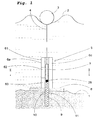
図1は、本発明に係る波力装置の原理を示す。浮体3は海面2に浮くように構成される。波は往復上下運動を浮体3に伝える。リニア発電機5は、底が固定された台板8を介して海底に固定される。台板はコンクリート製とすることができる。リニア発電機のステータ6a、6cは台板8に固定される。ステータは四つの垂直柱状積層スタックから成り、そのうちの二つだけが図示されている。発電機のロータ7は積層スタック間に配設され、ケーブル4によって浮体3に接続される。ロータ7は永久磁石を材料とする。
FIG. 1 shows the principle of a wave power device according to the present invention. The floating
台板8は中心に配置された穴10を有し、これと同心状に底凹所9が海底に形成される。凹所9は適切にライニングすることができる。引張りばね11が凹所9の下端に固定され、ばねの他端はロータ7の下端に取り付けられる。台板8の穴10及び凹所9の直径は、ロータ7がその中を自由に移動できるようにする。
The
各積層スタック6a、6cは複数のモジュールから構成される。図示した例では、積層スタック6aは、それが縦方向に配設された三つのモジュール61、62、63にいかに分割されるかを示すように印が付いている。
Each
海面2の波の運動のため、浮体3が上下に移動すると、この動きはケーブル4を介してロータ7に伝達され、したがってそれは積層スタック間で同等の往復運動を獲得する。したがってステータ巻線に電流が発生する。凹所9は、ロータが下降運動時にステータ全体を通過することを可能にする。引張りばね11は、ケーブル4が常にピンと張った状態に維持されるように、下降運動に力を加える。
As the
ばねはまた、特定の状況で上向きの力を与えることもできるように設計することもできる。ばねのばね率は、できるだけ多くの時間に共振が実現されるように、制御手段28によって制御することができる。 The spring can also be designed to provide an upward force in certain situations. The spring rate of the spring can be controlled by the control means 28 so that resonance is realized in as much time as possible.
ステータは、塩水に耐えることができるように、完全に又は部分的にVPI又はシリコンを含浸させることができる。 The stator can be fully or partially impregnated with VPI or silicon so that it can withstand salt water.
図2は、図1の線II−IIに沿った断面図である。この例では、ロータ7は正方形断面を持ち、積層スタック6a〜6dはロータ7の各辺に配設される。12a〜12dはそれぞれの積層スタックの巻線を表わす。各積層スタックのプレートの向きも図から明らかである。ロータと隣接する積層スタックとの間の空隙は数mm程度である。
2 is a cross-sectional view taken along line II-II in FIG. In this example, the
対応する断面図で、図3は、ロータ7の横断面が八面体の形状であり、したがって積層スタックの数が8個である代替実施形態を示す。
In a corresponding cross-sectional view, FIG. 3 shows an alternative embodiment in which the cross section of the
ロータの横断面の形状は任意の数の辺を持つ多角形とすることができることを理解されたい。多角形は正多角形であることが好ましいが、必ずしもそうである必要は無い。ロータは円形にすることもできる。積層スタックをロータの周囲全体で様々な方向に向けて配設することによって、できるだけ多くの磁界が電流を誘導するために利用される。 It should be understood that the cross-sectional shape of the rotor can be a polygon with any number of sides. The polygon is preferably a regular polygon, but this is not necessarily so. The rotor can also be circular. By arranging the stacked stack in various directions around the circumference of the rotor, as much magnetic field as possible is utilized to induce the current.
図4は、積層スタックの一つのモジュール61を斜視図で示す。該モジュールは、ボルト14によって一つに保持され、巻線12用のスロット15を設けた、階層状のプレート13から成る。極間距離a、すなわち巻線層間の距離は、特定のステータの長さに対してできるだけ多くの極を得、それによって誘導電流に高い周波数を得るために、できるだけ小さくする必要がある。実用的に適切な極間距離は約8mmであり、スロット幅は約4mmであり、したがってプレートの歯の幅も4mmである。
FIG. 4 is a perspective view showing one
積層スタックは、一つ又はそれ以上のそのようなモジュールから構成することができる。各モジュールは、図4に示すように、通常複数の極を有する。しかし、各モジュールに極が一つしか無いモジュールも選択肢である。 A stacked stack can be composed of one or more such modules. Each module typically has a plurality of poles as shown in FIG. However, a module with only one pole in each module is also an option.
ステータ巻線12は、図5に示すように、様々な積層スタック6a〜6dに共通することができる。
The stator winding 12 can be common to the
図6は、各積層スタックが個別の巻線を有する代替例を示す。この図は、二つの極を持つモジュールを示す。 FIG. 6 shows an alternative where each stack stack has a separate winding. This figure shows a module with two poles.
巻線の絶縁は、塩水に耐性を持つ一つの層を含み、それは最高6kVまでの電圧に耐えることができる。この層は、PVC又は類似物のようなポリマとすることができる。代替的に、エナメル線を使用することができる。導体はアルミ二ウム又は銅から構成される。 The winding insulation includes one layer that is resistant to salt water, which can withstand voltages up to 6 kV. This layer can be a polymer such as PVC or the like. Alternatively, enameled wire can be used. The conductor is made of aluminum or copper.
空隙をできるだけ小さくすることができるように、ロータ7の運動は注意深く規制することが重要である。リニア発電機の略断面図である図7は、これを単純かつ信頼できる方法でいかに実現できるかを示す。この場合、ロータは、隅を面取りした正方形の横断面を有する。各隅にガイド16a〜16bが配設される。各ガイドは、その下端を台板8(図1参照)に固定され、積層スタック6a〜6dと平行に縦方向に上向きに延在する。4個のガイドはロータの運動の厳密に中心を合わせた規制を確実にする。
It is important to carefully regulate the movement of the
代替実施形態を図8に示す。この場合、ロータ7は、その中を長手方向に貫通する中央の方形穴を持ち、そこに中央ガイド16が配設される。
An alternative embodiment is shown in FIG. In this case, the
図1に示した発電機は、ロータより約2倍の長さのステータ部を有する。図9は、代わりにロータ7がステータ6の約2倍の長さである代替実施形態を示す。
The generator shown in FIG. 1 has a stator portion that is approximately twice as long as the rotor. FIG. 9 shows an alternative embodiment in which the
本発明に係る波力プラントは、二台又はそれ以上の上記の型の装置から構成される。図10は、これらがいかに連結されて給電網にエネルギを供給するかを示す。図示した例では、発電プラントは20a−20cで象徴的に示す3台の装置から構成される。各装置は遮断機又は接触器21及び整流器22を介して、図ではバイポーラ接続でインバータ23に接続される。装置20aの回路図だけが示されている。他の装置20b、20cが同様の仕方で接続されることは理解されるであろう。インバータ23は、おそらく変圧器24及び/又はフィルタを介して、三相電流を給電網25に供給する。整流器は、制御することができ、IGBT型、GTO型、又はサイリスタ型とすることができ、制御バイポーラ部品を含むダイオード、あるいは制御できないダイオードとすることができる。
The wave power plant according to the present invention comprises two or more devices of the above type. FIG. 10 shows how they are connected to supply energy to the power grid. In the illustrated example, the power plant is composed of three devices, symbolically 20a-20c. Each device is connected to an
DC側の電圧は、並列もしくは直列で、又はそれらを組み合せて接続することができる。 The DC side voltage can be connected in parallel or in series, or a combination thereof.
図11に斜視図で示すロータ7は、ロータ本体27の各辺に一列に配置された複数の永久磁石26を備える。この例では、ロータは四辺を持ち、4個の積層スタックと協働する。
The
永久磁石26は、様々な型のロータの形状、例えば外周の異なる長さ及び異なる辺数に対して、適切に同一設計を持つことができる。永久磁石は次いでロータ本体27に取り付けられる。ロータ本体もまた標準設計とし、ロータが何個の辺を持つかによって個々に調整することができる。
The
図12は、ケーブル4にその動作長すなわち浮体3とロータ7との間の距離を制御する制御手段をいかに設けるかを示す。この場合、制御手段は、浮体に取り付けられたシリンダ29から成り、その上にケーブルの一部を巻きつけることができる。制御手段は他の方法で設計し、代替的にケーブルからロータへの接続部、又はケーブルの途中のどこかに配設することができる。制御手段は、様々な潮汐水の状態に合わせてケーブルの長さを調整することを可能にする。それはまた、浮体を水面の直下に配置するためにも使用することができる。接続手段がケーブルではない場合、例えばワイヤ又はチェーン、又は接合ロッドである場合、それに適した制御手段を使用する必要がある。
FIG. 12 shows how the
図13は、ケーブルが歯車機構を介してロータに接続される実施形態を示す。図示した例では、歯車機構は、ケーブルに固定され、かつ液体が充填された容器32内で、密閉状態で上下運動するように構成されたピストン30、又はロータ7に接続され、かつ同様に容器32内で上下運動するように構成されたピストン31から構成される。ケーブル4及び容器32の一部に接続されてそれらと協働するピストン30は、ロータ7及び容器32の一部に接続されてそれらと協働するピストン31より大きい直径を持つ。容器のピストンは適切に固定される。この構成は、ケーブルの上下運動とロータとの上下運動との間に、ピストン間の面積比に対応する比を生じる。歯車機構は代替的にリンクシステム又は歯車駆動装置の形を取るか、あるいは様々なピッチのねじを使用することができる。歯車機構はまた、歯車比の調整ができるように設計することもできる。
FIG. 13 shows an embodiment in which the cable is connected to the rotor via a gear mechanism. In the illustrated example, the gear mechanism is connected to a
図14に示した実施形態では、各積層スタック6a、6cはスタンド部33a、33c上に載置される。各スタンド部は、海底1に載置された台板8に固定される。スタンド部33a、33cの高さは少なくともロータ7の長さと同じ大きさであるので、これはステータ6を全て通り過ぎることができる。台板8及びスタンド部33a、33cはコンクリートに適切に埋め込まれ、それらの質量は数十トンとする必要がある。
In the embodiment shown in FIG. 14, the
図15に示した実施形態では、リニア発電機全体が、ハウジング34及び台板8によって形成されたコンクリート製のケーシング内に密閉される。
In the embodiment shown in FIG. 15, the entire linear generator is sealed in a concrete casing formed by the
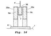
図16の例では、各積層スタック6a、6cはコンクリートケーシング35a、35cに埋め込まれる。ロータ7もまたコンクリートケーシング36内に密閉される。
In the example of FIG. 16, each
図17は、リニア発電機の代替実施形態の断面図を示す。この例では八角形で中空のロータ7は、各積層スタック6a、6b等と協働する外側を向いた永久磁石26、及びロータ7の内側の中心に配設された八角形の積層スタックと協働する内側を向いた永久磁石26aの両方を有する。
FIG. 17 shows a cross-sectional view of an alternative embodiment of a linear generator. In this example, the octagonal and
図18は、浮体3が、二台の異なるリニア発電機のロータ7a、7bに共通する例を示す。ケーブル4は、ケーブル4a、4bによって各ロータ7a、7bに接続された水平ロッド38に接続される。
FIG. 18 shows an example in which the floating
図19は、複数の同一ステータモジュール6及び複数の同一永久磁石26を持つ構成要素のシステムを示す。構成要素を使用して、任意の長さ及び横断面のリニア発電機を組み立てることができる。各モジュールは、個別構成要素として試験することができるように適切に設計される。
FIG. 19 shows a component system having a plurality of
図20は、連結された幾つかの発電機20、20b、20cを有する波力プラントを示す。整流器が各発電機に配設され、DC電流は、海底に配設されたケーブル39を介して、インバータ23、変圧器24、及びフィルタ41を装備した陸上のステーションに伝送され、そこから電力は配電又は送電網に供給される。
FIG. 20 shows a wave power plant having
図21は、本発明の別の有利な実施形態を示す基本レイアウトスケッチである。開閉所は、海底Bに載置して配設される。開閉所101は、例えばコンクリート製とすることができるハウジング102及び底板103によって形成される水密容器から成る。開閉所101は海底Bに固定される。複数の波力装置の発電機104〜109は開閉所に接続される。
FIG. 21 is a basic layout sketch illustrating another advantageous embodiment of the present invention. The switchyard is placed on the seabed B. The
各波力装置104〜109は、ハウジング102の引込み線を介して開閉所内の構成要素に接続されるケーブル110〜105によって、開閉所101と電気的に接続される。電圧は各装置から低電圧の直流又は交流電圧として供給される。
Each of the
開閉所101の構成要素は従来型であり、図には示さない。これらの構成要素は変圧器だけでなく、半導体、変換器、遮断機、測定装置、リレー保護、サージダイバータ、及び他の過電圧保護装置、接地手段、負荷連結器又は断路器をも含むことができる。
The components of the
開閉所は、送電ケーブル116を介して、好ましくは高電圧の送電直流又は交流電圧を供給する。交流電圧は低周波数を持ち、三相又は多相とすることができる。50又は60Hzの標準周波数を使用することもできる。
The switchgear preferably supplies a high-voltage transmission DC or AC voltage via the
受電低電圧は、開閉所の変圧器によって送電高電圧に変換される。開閉所の変換器又はインバータは、DC−AC変換又はその逆の変換に必要なときに使用される。 The received low voltage is converted into a high transmission voltage by a transformer in the switch station. Switchgear converters or inverters are used when necessary for DC-AC conversion or vice versa.
電圧は、おそらく中間所を介して陸上に位置する受電所に供給され、給電網に送り出される。 The voltage is supplied to a power station located on land, possibly via an intermediate station, and sent to a power supply network.
図22は、複数は発電装置がシステムに含まれる場合に得策な本発明に係るシステムの一例を示す。この図は、鳥瞰図で示したシステムの象徴的な表現であり、図の左側に海洋領域Hを、右側に陸上領域Lを示す。図の左側の構成要素は部分的に水面下に配置され、部分的に水面上に配置される。 FIG. 22 shows an example of a system according to the present invention that is suitable when a plurality of power generation devices are included in the system. This figure is a symbolic representation of the system shown in a bird's eye view, with the ocean region H on the left side and the land region L on the right side. Components on the left side of the figure are partially disposed below the water surface and partially disposed on the water surface.
システムは、第一群の発電装置104a〜106a、第二群の発電装置104b〜106b、及び第三群の発電装置104c〜106cを含む。第一群の発電装置104a〜106aは水中ケーブルを介して、水面下に位置する第一開閉所101aに接続される。同様に、他の二群の発電機104b〜106b及び104c〜106cは、第二開閉所101b及び第三回閉所101cにそれぞれ接続される。開閉所101a〜101cの各々は、水中ケーブル116a〜116cを介して、同じく水面下に位置する中間所117に接続される。電圧は中間所117から低周波三相交流電圧として水中ケーブル118を介して、陸上に位置する受電所119に伝送される。電圧は受電所で50又は60Hzのような標準周波数に変換される。
The system includes a first group of
発電装置と中間所との間の距離は1キロメートルから数十キロメートルまでに及ぶことがある。システムが図22に示すように構成された場合、片側の開閉所及び中間所から反対側の中間所及び受電所までの距離は最適化することができる。 The distance between the generator set and the intermediate station can range from one kilometer to several tens of kilometers. When the system is configured as shown in FIG. 22, the distance from the switch station and middle station on one side to the middle and power station on the opposite side can be optimized.
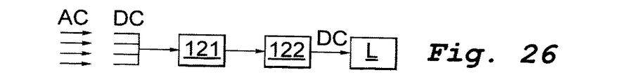
発電装置から陸上の受電所までの伝送は、様々な電圧変換器により様々な方法で行なうことができる。図23ないし26は、これの幾つかの例を概略的に示す。各例で、発電装置は図の左側に、陸上Lの受電所は右側に配設される。121は変換器/インバータを表わし、122は昇圧器を表わす。図23及び24で、発電装置は直流電圧を供給し、それは図23では交流電圧として陸上に伝送され、図24では直流電圧として伝送される。 Transmission from the power generator to the land power station can be performed in various ways by various voltage converters. Figures 23 to 26 schematically show some examples of this. In each example, the power generation device is disposed on the left side of the figure, and the land L power station is disposed on the right side. 121 represents a converter / inverter, and 122 represents a booster. 23 and 24, the power generator supplies a DC voltage, which is transmitted to the land as an AC voltage in FIG. 23 and is transmitted as a DC voltage in FIG.
図25及び26で、発電装置は交流電圧を供給し、それは直流電圧に変換される。図25でそれは陸上に交流電圧として伝送され、図26では直流電圧として伝送される。 In FIGS. 25 and 26, the power generator supplies an alternating voltage, which is converted to a direct voltage. In FIG. 25, it is transmitted to the land as an AC voltage, and in FIG. 26, it is transmitted as a DC voltage.
本発明の範囲内で他の多くの代替例が実現可能である。例えば、図27に示した型の全波整流器を使用することができる。 Many other alternatives are possible within the scope of the present invention. For example, a full wave rectifier of the type shown in FIG. 27 can be used.
エネルギ貯蔵装置及びフィルタも各開閉所101、及び/又は中間所117に収容することができる。エネルギ貯蔵装置は例えばバッテリ、コンデンサ、SMES型、フライホイール、又はそれらの組合せから構成することができる。フィルタは、変換器と同様に可動部品を含むことができる。受動LCフィルタ、及びフライホイール変換器又は同期コンデンサのような電子機械的部品も可能である。
An energy storage device and a filter can also be accommodated in each switching
Claims (49)
前記ステータ(6)および前記ロータ(7)の全体が前記浮体(3)の下方において水中に沈められており、
前記ロータ(7)が永久磁石であり、
前記ステータ(6)が前記ロータ(7)の運動の方向に分布する複数の極を形成する巻線を備え、
前記ロータ(7)に下向きの力を加えるようにばね手段(11)が配設されており、
前記ばね手段(11)は、前記海底/湖底(1)に設けられた凹所の底部と前記ロータ(7)とを接続しており、
前記接続手段(4)の一部分が可撓性であり、
前記ステータ(6)の巻線は、整流器(22)に接続されており、
一つ又はそれ以上のガイド要素(16)が前記ロータ(7)を規制するように構成されることを特徴とする、波力装置。The floating body (3) and the rotor (7) are connected to the floating body (3) by connection means (4), and the stator (6) is fixed so as not to move to the seabed / lake bottom (1). In the wave power device for power generation comprising the linear generator (5),
The whole of the stator (6) and the rotor (7) is submerged under the floating body (3),
The rotor (7) is a permanent magnet;
The stator (6) comprises windings forming a plurality of poles distributed in the direction of motion of the rotor (7);
Spring means (11) is arranged to apply a downward force to the rotor (7),
The spring means (11) connects the bottom of a recess provided in the seabed / lake bottom (1) and the rotor (7),
A part of said connecting means (4) is flexible;
The winding of the stator (6) is connected to a rectifier (22),
Wave device, characterized in that one or more guide elements (16) are arranged to regulate the rotor (7).
ないし7のいずれか一項に記載の波力装置。6. The rotor according to claim 5, wherein the rotor includes a plurality of permanent magnets distributed on an outer periphery thereof, and the permanent magnets are disposed so as to face the direction of each stacked stack in an arbitrary cross section of the rotor.
The wave power device as described in any one of thru | or 7.
Applications Claiming Priority (5)
| Application Number | Priority Date | Filing Date | Title |
|---|---|---|---|
| SE0200065-1 | 2002-01-10 | ||
| SE0200065A SE520921C2 (en) | 2002-01-10 | 2002-01-10 | Wave power unit for generation of electricity has a float that moves with the waves and is mechanically coupled to a linear generator |
| SE0200613-8 | 2002-02-28 | ||
| SE0200613A SE524852C2 (en) | 2002-01-08 | 2002-02-28 | Wave power electricity generator has stator with winding connected to rectifier and movement transmitter converting vertical movement of floating body into rotor turns |
| PCT/SE2002/002405 WO2003058055A1 (en) | 2002-01-10 | 2002-12-19 | A wave-power unit and the use of a wave-power unit for production of electric power, a method of generating electric power and a system of components for manufacturing a linear generator for a wave-power unit |
Publications (2)
| Publication Number | Publication Date |
|---|---|
| JP2005531707A JP2005531707A (en) | 2005-10-20 |
| JP4732690B2 true JP4732690B2 (en) | 2011-07-27 |
Family
ID=26655649
Family Applications (1)
| Application Number | Title | Priority Date | Filing Date |
|---|---|---|---|
| JP2003558334A Expired - Lifetime JP4732690B2 (en) | 2002-01-10 | 2002-12-19 | Wave power device, use of wave power device for power generation, power generation method, and set of components for manufacturing linear generator for wave power device |
Country Status (15)
| Country | Link |
|---|---|
| EP (1) | EP1474607B1 (en) |
| JP (1) | JP4732690B2 (en) |
| CN (1) | CN1615400B (en) |
| AT (1) | ATE369492T1 (en) |
| AU (1) | AU2002359188B2 (en) |
| CA (1) | CA2472942C (en) |
| CY (1) | CY1106906T1 (en) |
| DE (1) | DE60221712T2 (en) |
| DK (1) | DK1474607T3 (en) |
| ES (1) | ES2291525T3 (en) |
| NZ (1) | NZ534543A (en) |
| PT (1) | PT1474607E (en) |
| TW (2) | TWI276741B (en) |
| WO (1) | WO2003058055A1 (en) |
| ZA (1) | ZA200406297B (en) |
Families Citing this family (48)
| Publication number | Priority date | Publication date | Assignee | Title |
|---|---|---|---|---|
| SE522999C2 (en) * | 2003-03-27 | 2004-03-23 | Swedish Seabased Energy Ab | Wave power unit |
| SE0300869L (en) * | 2003-03-27 | 2004-03-23 | Swedish Seabased Energy Ab | Wave power units |
| SE523478C2 (en) * | 2003-04-14 | 2004-04-20 | Swedish Seabased Energy Ab | Wave energy machine, includes linear electric generator with electromagnetic damping devices |
| CA2536603C (en) * | 2004-03-16 | 2013-11-26 | Ocean Power Technologies, Inc. | Wave energy converters (wecs) with linear electric generators (legs) |
| DK1831542T3 (en) * | 2004-12-02 | 2016-12-12 | Wave Energy Tech Inc | Energy devices |
| GB2424523A (en) * | 2005-03-21 | 2006-09-27 | Alstom | Electronically commutated electrical machine |
| GB2430560A (en) * | 2005-09-22 | 2007-03-28 | Alstom Power Conversion Ltd | Laminated stator for tubular electrical machines |
| US7345372B2 (en) * | 2006-03-08 | 2008-03-18 | Perpetuum Ltd. | Electromechanical generator for, and method of, converting mechanical vibrational energy into electrical energy |
| RU2405966C2 (en) * | 2006-03-29 | 2010-12-10 | Сибэйсд Аб | System for electrical energy production |
| AU2006340933B2 (en) * | 2006-03-29 | 2011-12-22 | Seabased Ab | A system for generating electric energy |
| NO20071963A (en) * | 2007-04-17 | 2008-08-11 | Straumekraft As | Device at wave power plant |
| DK2134960T3 (en) * | 2007-04-18 | 2017-03-13 | Seabased Ab | WAVE POWER UNIT, BEND, USE OF A WAVE POWER UNIT AND METHOD FOR PRODUCING ELECTRICAL ENERGY |
| PL2318696T3 (en) | 2008-08-26 | 2019-05-31 | Seabased Ab | A wave-power unit |
| DK2315937T3 (en) | 2008-08-26 | 2018-07-23 | Seabased Ab | A WAVE ENERGY UNIT |
| ES2720360T3 (en) * | 2008-08-28 | 2019-07-19 | Seabased Ab | A unit of wave energy and use of it |
| DE202008018088U1 (en) | 2008-10-02 | 2011-08-08 | Robert Schlager | Wave power plant for converting energy contained in the wave motion of water |
| DE102008050238B4 (en) | 2008-10-02 | 2011-07-28 | Schlager, Robert, 68549 | Wave power plant for converting energy contained in the wave motion of water |
| US20110221192A1 (en) * | 2008-12-09 | 2011-09-15 | Siemens Aktiengesellschaft | Generator for generating eletrical energy from mechanical vibrations, and method for adjusting the resonant frequency of such a generator |
| EP2389507A4 (en) * | 2009-01-23 | 2013-07-24 | Seabased Ab | A wave power unit |
| FR2946970B1 (en) * | 2009-06-23 | 2011-07-15 | Commissariat Energie Atomique | MICROMECHANICAL DEVICE FOR AMPLIFYING VIBRATION MOVEMENT |
| DE202009013513U1 (en) | 2009-10-07 | 2010-01-14 | Schlager, Robert | Wave power plant for converting energy contained in the wave motion of water |
| KR101076080B1 (en) * | 2009-11-18 | 2011-10-21 | 김종철 | Ocean Energy Converter |
| KR101181568B1 (en) | 2010-02-16 | 2012-09-10 | 박찬희 | Wave power generator using up and down motion of wave |
| CA2799626C (en) | 2010-05-28 | 2019-03-19 | Seabased Ab | A linear generator for submerged use and a method of producing electric energy |
| PL2577849T3 (en) * | 2010-05-28 | 2021-07-05 | Seabased Ab | Stator frame for a submerged linear generator |
| JP5805753B2 (en) * | 2010-05-28 | 2015-11-04 | シーベイスト アクチボラグSeabased AB | Wave power generator, use thereof, and method of generating electrical energy |
| BR112012030280A2 (en) | 2010-05-28 | 2016-08-09 | Seabased Ab | wave energy production unit comprising a guide device |
| KR101145084B1 (en) | 2010-06-03 | 2012-05-11 | 이형우 | Wave power generator |
| CN102934337B (en) * | 2010-06-09 | 2016-04-27 | 株式会社日立制作所 | The Blast Furnace Top Gas Recovery Turbine Unit (TRT) of generator and use generator |
| KR101787563B1 (en) | 2010-12-09 | 2017-10-17 | 시베이스드 아베 | An electric device and a method for producing and supplying electric energy, a wave power plant including a plurality of electric devices, an electric network including at least one electric device and a use of an electronic device |
| MX2011004900A (en) * | 2011-05-09 | 2012-11-21 | Maremotrices De En Renovables S A De C V | System for converting wave impact into energy using piezoelectric, hydraulic, magnetic and other means. |
| CN102810971A (en) * | 2011-05-31 | 2012-12-05 | 陈振 | Sway plug-in generator |
| CN103066781B (en) * | 2011-10-19 | 2015-04-01 | 上海南洋电机有限公司 | Linear generator used for sea wave power generation |
| CN103423071A (en) * | 2012-05-15 | 2013-12-04 | 王维俊 | Novel highly-efficient multipoint absorbing wave energy power generation device |
| CN103758681B (en) * | 2013-12-26 | 2016-01-20 | 宁波大学 | A kind of multistage combined generating device |
| CN104335962A (en) * | 2014-09-10 | 2015-02-11 | 长沙理工大学 | Oscillating float type wave energy oxygen supply device |
| CN104500321B (en) * | 2014-11-04 | 2017-11-14 | 集美大学 | Wave energy differential linear electric generator |
| JP6655849B2 (en) * | 2015-04-24 | 2020-02-26 | 株式会社三井E&Sマシナリー | Coastal wave power generation system |
| CN104976047A (en) * | 2015-06-19 | 2015-10-14 | 电子科技大学 | Direct drive type wave power generation system utilizing superconducting coils |
| EP3850211A4 (en) * | 2018-09-14 | 2022-09-28 | Ocean Harvesting Technologies AB | POWER TAKE-OFF DEVICE FOR USE IN A TIDAL POWER CONVERTER |
| CN110230567B (en) * | 2019-06-25 | 2020-06-23 | 浙江大学 | Wave energy power generation device with energy capturing mechanism with adjustable quality and control method thereof |
| KR102136490B1 (en) | 2019-07-10 | 2020-07-21 | 이순선 | Apparatus for generating electricity using flow of sea water |
| CN110943455B (en) * | 2020-01-14 | 2025-04-22 | 浙江大学建筑设计研究院有限公司 | A multi-location start-stop control device and design method thereof |
| CN111189434B (en) * | 2020-01-17 | 2021-08-06 | 哈尔滨工业大学 | A wave height meter capable of measuring the liquid level of air-entrained waves |
| EP3922838A1 (en) * | 2020-06-08 | 2021-12-15 | Seabased AB | Array for arranging wave energy converters in a wave power park |
| CN114753961A (en) * | 2022-03-18 | 2022-07-15 | 湖南大学 | Multi-directional bistable wave energy converter |
| CN116207628A (en) * | 2023-03-21 | 2023-06-02 | 安徽龙和电力集团有限公司 | A smart grid monitoring and management device |
| CN116428097B (en) * | 2023-04-07 | 2025-05-02 | 中国长江三峡集团有限公司 | Power generation mechanism, wave power generator and wave power generation system |
Family Cites Families (25)
| Publication number | Priority date | Publication date | Assignee | Title |
|---|---|---|---|---|
| JPS5431516A (en) * | 1977-08-13 | 1979-03-08 | Namiko Kuroda | Wave generator |
| JPS55160967A (en) * | 1979-05-30 | 1980-12-15 | Yasuhiro Manabe | Multimagnet electric generator employing vertical motion of wave |
| US4256970A (en) * | 1979-06-25 | 1981-03-17 | Eugene Pascucci | Apparatus for the exploitation of underwater currents for the production of electrical energy |
| JPS5654968A (en) * | 1979-10-09 | 1981-05-15 | Takeshi Umemoto | Power-generating plant using displacement of surface of sea |
| US4539485A (en) * | 1983-10-07 | 1985-09-03 | Neuenschwander Victor L | Wave activated generator |
| JPS61218780A (en) * | 1985-03-23 | 1986-09-29 | Yasuhiro Manabe | Stationary wave-prime mover |
| US4754157A (en) * | 1985-10-01 | 1988-06-28 | Windle Tom J | Float type wave energy extraction apparatus and method |
| JPS62126275A (en) * | 1985-11-25 | 1987-06-08 | Kajima Corp | Wave activated power generation plant |
| DE3642723A1 (en) * | 1986-12-13 | 1988-06-23 | Grundfos Int | STATIC FREQUENCY INVERTER, ESPECIALLY FREQUENCY INVERTER FOR CONTROLLING AND / OR REGULATING THE PERFORMANCE SIZE OF AN ELECTRIC MOTOR |
| JPH01164256A (en) * | 1987-12-18 | 1989-06-28 | Aisin Seiki Co Ltd | linear generator |
| JPH0743304Y2 (en) * | 1989-06-30 | 1995-10-09 | 新日本製鐵株式会社 | Cage-shaped rebar |
| JPH03124973A (en) * | 1989-10-06 | 1991-05-28 | J Windle Tom | Wave pump device and method |
| JPH0419363A (en) * | 1990-05-14 | 1992-01-23 | Taiyo Plant Kogyo:Yugen | Vibration pump with use of spring |
| GB2272026A (en) * | 1992-10-29 | 1994-05-04 | William Chilton | Electrical power generation from waves |
| NL9302230A (en) * | 1993-12-21 | 1995-07-17 | Fred Ernest Gardner | Wave energy converter. |
| JPH089650A (en) * | 1994-04-22 | 1996-01-12 | Nippon Electric Ind Co Ltd | System interlocking inverter system |
| US5910691A (en) * | 1995-03-20 | 1999-06-08 | Wavre; Nicolas | Permanent-magnet linear synchronous motor |
| US5929541A (en) * | 1996-11-26 | 1999-07-27 | Kinsiro Naito | Synchronous machine |
| NL1005542C2 (en) * | 1997-03-14 | 1998-09-15 | Zakaria Khalil Doleh | Device for the conversion of energy from the vertical movement of sea water. |
| JPH10323002A (en) * | 1997-05-21 | 1998-12-04 | Matsushita Refrig Co Ltd | Linear motor |
| US6020653A (en) * | 1997-11-18 | 2000-02-01 | Aqua Magnetics, Inc. | Submerged reciprocating electric generator |
| WO1999028623A1 (en) * | 1997-12-03 | 1999-06-10 | William Dick | A wave energy converter |
| GB2351124B (en) * | 1999-06-03 | 2004-02-04 | Anthony Moore | A method of constructing, installing and operating a marine power station |
| GB9916779D0 (en) * | 1999-07-16 | 1999-09-15 | Kelly H P G | Sea wave to electrical energy conversion plant |
| JP4009403B2 (en) * | 2000-03-29 | 2007-11-14 | 株式会社ソディック | Modular coil side linear motor |
-
2002
- 2002-12-19 NZ NZ534543A patent/NZ534543A/en not_active IP Right Cessation
- 2002-12-19 CA CA2472942A patent/CA2472942C/en not_active Expired - Lifetime
- 2002-12-19 AT AT02793706T patent/ATE369492T1/en not_active IP Right Cessation
- 2002-12-19 WO PCT/SE2002/002405 patent/WO2003058055A1/en not_active Ceased
- 2002-12-19 CN CN028270541A patent/CN1615400B/en not_active Expired - Fee Related
- 2002-12-19 DK DK02793706T patent/DK1474607T3/en active
- 2002-12-19 DE DE60221712T patent/DE60221712T2/en not_active Expired - Lifetime
- 2002-12-19 AU AU2002359188A patent/AU2002359188B2/en not_active Expired
- 2002-12-19 EP EP02793706A patent/EP1474607B1/en not_active Expired - Lifetime
- 2002-12-19 JP JP2003558334A patent/JP4732690B2/en not_active Expired - Lifetime
- 2002-12-19 ES ES02793706T patent/ES2291525T3/en not_active Expired - Lifetime
- 2002-12-19 PT PT02793706T patent/PT1474607E/en unknown
-
2003
- 2003-01-06 TW TW092100176A patent/TWI276741B/en not_active IP Right Cessation
- 2003-01-06 TW TW092100175A patent/TW200302317A/en unknown
-
2004
- 2004-08-06 ZA ZA2004/06297A patent/ZA200406297B/en unknown
-
2007
- 2007-10-04 CY CY20071101266T patent/CY1106906T1/en unknown
Also Published As
| Publication number | Publication date |
|---|---|
| AU2002359188A1 (en) | 2003-07-24 |
| EP1474607B1 (en) | 2007-08-08 |
| TW200301799A (en) | 2003-07-16 |
| CA2472942C (en) | 2010-03-16 |
| CY1106906T1 (en) | 2012-09-26 |
| EP1474607A1 (en) | 2004-11-10 |
| ATE369492T1 (en) | 2007-08-15 |
| WO2003058055A1 (en) | 2003-07-17 |
| TW200302317A (en) | 2003-08-01 |
| NZ534543A (en) | 2005-06-24 |
| ES2291525T3 (en) | 2008-03-01 |
| JP2005531707A (en) | 2005-10-20 |
| AU2002359188B2 (en) | 2008-08-28 |
| CN1615400B (en) | 2010-06-09 |
| TWI276741B (en) | 2007-03-21 |
| DE60221712T2 (en) | 2008-05-15 |
| ZA200406297B (en) | 2005-11-30 |
| DK1474607T3 (en) | 2007-12-27 |
| CA2472942A1 (en) | 2003-07-17 |
| PT1474607E (en) | 2007-11-13 |
| CN1615400A (en) | 2005-05-11 |
| DE60221712D1 (en) | 2007-09-20 |
Similar Documents
| Publication | Publication Date | Title |
|---|---|---|
| JP4732690B2 (en) | Wave power device, use of wave power device for power generation, power generation method, and set of components for manufacturing linear generator for wave power device | |
| US7164212B2 (en) | Electric device and method | |
| US7045912B2 (en) | Wave-power electric device and method | |
| CN100455792C (en) | Wave power assembly with electromagnetic damping device | |
| CN100412355C (en) | wave energy device | |
| IL193724A (en) | System for generating electric energy | |
| KR20030083253A (en) | Generation device of electricity by using the wave | |
| KR101787563B1 (en) | An electric device and a method for producing and supplying electric energy, a wave power plant including a plurality of electric devices, an electric network including at least one electric device and a use of an electronic device | |
| KR200376925Y1 (en) | Automatic generation device of electricity by using vibration | |
| CN116428097B (en) | Power generation mechanism, wave power generator and wave power generation system | |
| HK1076850A (en) | A wave-power unit and the use of a wave-power unit for production of electric power, a method of generating electric power and a system of components for manufacturing a linear generator for a wave-power unit | |
| HK1131813B (en) | A system for generating electric energy |
Legal Events
| Date | Code | Title | Description |
|---|---|---|---|
| A621 | Written request for application examination |
Free format text: JAPANESE INTERMEDIATE CODE: A621 Effective date: 20051114 |
|
| A131 | Notification of reasons for refusal |
Free format text: JAPANESE INTERMEDIATE CODE: A131 Effective date: 20080603 |
|
| A601 | Written request for extension of time |
Free format text: JAPANESE INTERMEDIATE CODE: A601 Effective date: 20080828 |
|
| A602 | Written permission of extension of time |
Free format text: JAPANESE INTERMEDIATE CODE: A602 Effective date: 20080904 |
|
| A601 | Written request for extension of time |
Free format text: JAPANESE INTERMEDIATE CODE: A601 Effective date: 20080929 |
|
| A602 | Written permission of extension of time |
Free format text: JAPANESE INTERMEDIATE CODE: A602 Effective date: 20081006 |
|
| A601 | Written request for extension of time |
Free format text: JAPANESE INTERMEDIATE CODE: A601 Effective date: 20081030 |
|
| A602 | Written permission of extension of time |
Free format text: JAPANESE INTERMEDIATE CODE: A602 Effective date: 20081107 |
|
| A521 | Request for written amendment filed |
Free format text: JAPANESE INTERMEDIATE CODE: A523 Effective date: 20081113 |
|
| A131 | Notification of reasons for refusal |
Free format text: JAPANESE INTERMEDIATE CODE: A131 Effective date: 20090623 |
|
| A601 | Written request for extension of time |
Free format text: JAPANESE INTERMEDIATE CODE: A601 Effective date: 20090908 |
|
| A602 | Written permission of extension of time |
Free format text: JAPANESE INTERMEDIATE CODE: A602 Effective date: 20090915 |
|
| A601 | Written request for extension of time |
Free format text: JAPANESE INTERMEDIATE CODE: A601 Effective date: 20091023 |
|
| A602 | Written permission of extension of time |
Free format text: JAPANESE INTERMEDIATE CODE: A602 Effective date: 20091030 |
|
| A521 | Request for written amendment filed |
Free format text: JAPANESE INTERMEDIATE CODE: A523 Effective date: 20091117 |
|
| A02 | Decision of refusal |
Free format text: JAPANESE INTERMEDIATE CODE: A02 Effective date: 20100608 |
|
| A521 | Request for written amendment filed |
Free format text: JAPANESE INTERMEDIATE CODE: A523 Effective date: 20101008 |
|
| A521 | Request for written amendment filed |
Free format text: JAPANESE INTERMEDIATE CODE: A523 Effective date: 20101018 |
|
| A911 | Transfer to examiner for re-examination before appeal (zenchi) |
Free format text: JAPANESE INTERMEDIATE CODE: A911 Effective date: 20101112 |
|
| A131 | Notification of reasons for refusal |
Free format text: JAPANESE INTERMEDIATE CODE: A131 Effective date: 20101228 |
|
| A521 | Request for written amendment filed |
Free format text: JAPANESE INTERMEDIATE CODE: A523 Effective date: 20110302 |
|
| TRDD | Decision of grant or rejection written | ||
| A01 | Written decision to grant a patent or to grant a registration (utility model) |
Free format text: JAPANESE INTERMEDIATE CODE: A01 Effective date: 20110329 |
|
| A61 | First payment of annual fees (during grant procedure) |
Free format text: JAPANESE INTERMEDIATE CODE: A61 Effective date: 20110421 |
|
| FPAY | Renewal fee payment (event date is renewal date of database) |
Free format text: PAYMENT UNTIL: 20140428 Year of fee payment: 3 |
|
| R150 | Certificate of patent or registration of utility model |
Ref document number: 4732690 Country of ref document: JP Free format text: JAPANESE INTERMEDIATE CODE: R150 Free format text: JAPANESE INTERMEDIATE CODE: R150 |
|
| R250 | Receipt of annual fees |
Free format text: JAPANESE INTERMEDIATE CODE: R250 |
|
| R250 | Receipt of annual fees |
Free format text: JAPANESE INTERMEDIATE CODE: R250 |
|
| R250 | Receipt of annual fees |
Free format text: JAPANESE INTERMEDIATE CODE: R250 |
|
| R250 | Receipt of annual fees |
Free format text: JAPANESE INTERMEDIATE CODE: R250 |
|
| R250 | Receipt of annual fees |
Free format text: JAPANESE INTERMEDIATE CODE: R250 |
|
| R250 | Receipt of annual fees |
Free format text: JAPANESE INTERMEDIATE CODE: R250 |
|
| S802 | Written request for registration of partial abandonment of right |
Free format text: JAPANESE INTERMEDIATE CODE: R311802 |
|
| R350 | Written notification of registration of transfer |
Free format text: JAPANESE INTERMEDIATE CODE: R350 |
|
| R250 | Receipt of annual fees |
Free format text: JAPANESE INTERMEDIATE CODE: R250 |
|
| R250 | Receipt of annual fees |
Free format text: JAPANESE INTERMEDIATE CODE: R250 |
|
| R250 | Receipt of annual fees |
Free format text: JAPANESE INTERMEDIATE CODE: R250 |
|
| EXPY | Cancellation because of completion of term |