JP4732910B2 - Apparatus and method for sterilizing objects by low energy electron impact - Google Patents
Apparatus and method for sterilizing objects by low energy electron impact Download PDFInfo
- Publication number
- JP4732910B2 JP4732910B2 JP2006023295A JP2006023295A JP4732910B2 JP 4732910 B2 JP4732910 B2 JP 4732910B2 JP 2006023295 A JP2006023295 A JP 2006023295A JP 2006023295 A JP2006023295 A JP 2006023295A JP 4732910 B2 JP4732910 B2 JP 4732910B2
- Authority
- JP
- Japan
- Prior art keywords
- axis
- sterilizing
- processing chamber
- mechanical module
- object according
- Prior art date
- Legal status (The legal status is an assumption and is not a legal conclusion. Google has not performed a legal analysis and makes no representation as to the accuracy of the status listed.)
- Expired - Fee Related
Links
Images


Classifications
-
- A—HUMAN NECESSITIES
- A61—MEDICAL OR VETERINARY SCIENCE; HYGIENE
- A61L—METHODS OR APPARATUS FOR STERILISING MATERIALS OR OBJECTS IN GENERAL; DISINFECTION, STERILISATION OR DEODORISATION OF AIR; CHEMICAL ASPECTS OF BANDAGES, DRESSINGS, ABSORBENT PADS OR SURGICAL ARTICLES; MATERIALS FOR BANDAGES, DRESSINGS, ABSORBENT PADS OR SURGICAL ARTICLES
- A61L2/00—Disinfection or sterilisation of materials or objects, in general; Accessories therefor
- A61L2/02—Disinfection or sterilisation of materials or objects, in general; Accessories therefor using physical processes
- A61L2/08—Radiation
- A61L2/087—Particle radiation, e.g. electron-beam, alpha or beta radiation
-
- A—HUMAN NECESSITIES
- A61—MEDICAL OR VETERINARY SCIENCE; HYGIENE
- A61L—METHODS OR APPARATUS FOR STERILISING MATERIALS OR OBJECTS IN GENERAL; DISINFECTION, STERILISATION OR DEODORISATION OF AIR; CHEMICAL ASPECTS OF BANDAGES, DRESSINGS, ABSORBENT PADS OR SURGICAL ARTICLES; MATERIALS FOR BANDAGES, DRESSINGS, ABSORBENT PADS OR SURGICAL ARTICLES
- A61L2103/00—Materials or objects being the target of disinfection or sterilisation
- A61L2103/15—Laboratory, medical or dentistry appliances, e.g. catheters or sharps
-
- A—HUMAN NECESSITIES
- A61—MEDICAL OR VETERINARY SCIENCE; HYGIENE
- A61L—METHODS OR APPARATUS FOR STERILISING MATERIALS OR OBJECTS IN GENERAL; DISINFECTION, STERILISATION OR DEODORISATION OF AIR; CHEMICAL ASPECTS OF BANDAGES, DRESSINGS, ABSORBENT PADS OR SURGICAL ARTICLES; MATERIALS FOR BANDAGES, DRESSINGS, ABSORBENT PADS OR SURGICAL ARTICLES
- A61L2202/00—Aspects relating to methods or apparatus for disinfecting or sterilising materials or objects
- A61L2202/10—Apparatus features
- A61L2202/12—Apparatus for isolating biocidal substances from the environment
- A61L2202/122—Chambers for sterilisation
Landscapes
- Health & Medical Sciences (AREA)
- Epidemiology (AREA)
- Life Sciences & Earth Sciences (AREA)
- Animal Behavior & Ethology (AREA)
- General Health & Medical Sciences (AREA)
- Public Health (AREA)
- Veterinary Medicine (AREA)
- Apparatus For Disinfection Or Sterilisation (AREA)
- Food Preservation Except Freezing, Refrigeration, And Drying (AREA)
Abstract
Description
この発明は、一般に、物体の外面に対する低エネルギー電子衝撃によって物体を殺菌する分野に関するものである。 The present invention relates generally to the field of sterilizing an object by low energy electron impact on the outer surface of the object.
それは特に、排他的ではないが、低エネルギー電子衝撃による略直方体形状を有する物体の殺菌に適用され、該物体は、例えば医療用注射器のような好ましくは化学的に予備殺菌された多数のエレメントを含んだ閉鎖された容器に相当する「タブ(tubs)」と呼ばれるものである。 It applies in particular, but not exclusively, to the sterilization of objects having a substantially rectangular shape by low-energy electron impact, the object comprising a number of preferably chemically pre-sterilized elements such as, for example, medical syringes. These are called “tubs” corresponding to the enclosed closed containers.
より詳しくは、本発明は、物体の表面に対する低エネルギー電子衝撃によって物体を殺菌するための装置と、そのような装置によって実行されうる殺菌方法とに関するものである。 More particularly, the present invention relates to an apparatus for sterilizing an object by low energy electron impact on the surface of the object and a sterilization method that can be performed by such an apparatus.
従来技術は、低エネルギー電子衝撃によって、つまり約400KeVよりも小さいエネルギーによって略直方体形状の物体を殺菌するための装置を含んでいる。 The prior art includes an apparatus for sterilizing a substantially cuboid shaped object by low energy electron bombardment, ie, by energy less than about 400 KeV.
このため、これらの装置は一般に、約200KeVの3つの低エネルギー加速器/銃タイプソースを備えており、該ソースは、物体を処理のために並進移動させて通過させる処理チャンバのまわりに、互いに関して120°で配置されている。このようにして、物体が処理チャンバを連続的を通過していくのにしたがい、各物体の外面は、注意深く位置決めされた上述のソースからの3つの電子ビームの組合せにより、360°にわたって同時に照らされる。 For this reason, these devices generally comprise three low energy accelerator / gun type sources of about 200 KeV, which are relative to each other around a processing chamber that translates and passes objects for processing. It is arranged at 120 °. In this way, as the objects pass continuously through the processing chamber, the outer surface of each object is illuminated simultaneously over 360 ° by a combination of three electron beams from the above-mentioned sources that are carefully positioned. .
このタイプの装置は、特に電子ビームの光浸透力および生成される殺胞子効果に関連するその有効性により、そしてまた、その急速処理および提供される安全性により、申し分ないものであることが分かっている。 This type of device proved to be satisfactory, especially due to its effectiveness in relation to the optical penetrating power of the electron beam and the generated sporicidal effect, and also due to its rapid processing and the safety provided. ing.
それにもかかわらず、この装置は、各物体の全ての外面の照射によって殺菌を実行するためには3つの異なった低エネルギー加速器/銃タイプソースを必要とするという事実に存在する重大な不具合を有している。もちろん、3つの複雑な低エネルギーソースの存在が必要となることに関連するこの制約は、装置を非常に高価なものとし、したがってそれは、完全には最適化されない。 Nevertheless, this device has a serious drawback present in the fact that it requires three different low energy accelerator / gun type sources to perform sterilization by irradiating all external surfaces of each object. is doing. Of course, this constraint associated with the need for the presence of three complex low energy sources makes the device very expensive and therefore it is not fully optimized.
さらに、この装置が特に大きな空間を要求することも、他の不具合を構成していることに留意されたい。 Furthermore, it should be noted that the fact that this device requires a particularly large space constitutes another drawback.
したがって、本発明の目的は、従来技術に関して上述した不具合を少なくとも部分的に克服する、物体の表面に対する低エネルギー電子衝撃によって物体を殺菌するための装置と、そのような装置によって実行されうる殺菌方法とを提案することである。 The object of the present invention is therefore an apparatus for sterilizing an object by low energy electron impact on the surface of the object, which at least partially overcomes the drawbacks mentioned above with respect to the prior art, and a sterilization method that can be performed by such an apparatus. It is to propose.
このため、本発明はまず、前記物体の外面に対する低エネルギー電子衝撃によって物体を殺菌するための装置に関するものであり、該装置は、装置の処理チャンバを通過する軸線Aに沿って低エネルギー電子ビームを発生させることができる殺菌手段を含んでいる。本発明によれば、それはまた、処理チャンバの内側に配置された処理される物体の殺菌中に、物体と殺菌手段との間の軸線A’まわりの相対的回転移動を生じさせることができるように構成された第1の機械式モジュールを含んでおり、該軸線A’は、前記軸線A’まわりの相対的回転移動の間に、殺菌手段によって発生される電子ビームの軸線Aが物体の外面を連続的に通過するように選択されている。加えて、該装置は、前記処理チャンバの内側に配置された物体が第1の機械式モジュールから解放されたときに、軸線A’に関して直交して方向付けられた軸線A”まわりの物体の回転を生じさせることができるように構成された第2の機械式モジュールを備えている。 For this reason, the present invention first relates to an apparatus for sterilizing an object by low energy electron impact on the outer surface of the object, which apparatus comprises a low energy electron beam along an axis A passing through the processing chamber of the apparatus. Including sterilizing means capable of generating According to the invention, it can also cause a relative rotational movement about the axis A ′ between the object and the sterilization means during sterilization of the object to be processed arranged inside the processing chamber. The axis A ′ is arranged so that the axis A of the electron beam generated by the sterilizing means during the relative rotational movement about the axis A ′ is the outer surface of the object. Is selected to pass continuously. In addition, the apparatus rotates the object about an axis A ″ oriented orthogonally with respect to the axis A ′ when the object located inside the processing chamber is released from the first mechanical module. A second mechanical module configured to be able to generate
言い換えると、本発明の特徴の1つは、前記相対的回転移動の間に物体の外面が連続的にかつ次第に処理されるように、殺菌手段と物体との間の相対的回転移動をもたらすことからなっている。 In other words, one of the features of the present invention is to provide a relative rotational movement between the sterilizing means and the object such that the outer surface of the object is continuously and gradually treated during the relative rotational movement. It is made up of.
本発明による装置では、共同してかつ同時に物体の外面を360°にわたって照らすように意図された3つの異なった低エネルギーソースの使用が、もはや必要なくなることが有利である。実際、提案された構成では、相対的回転移動の任意の時間tにおいて軸線Aに沿った電子ビームが物体の外面を360°より小さい角度でのみ照らす単一の低エネルギーソースを使用することにより、殺菌される物体を処理することができる。そしてそれは、物体の外面を連続的に通過する軸線A’に関する、好ましくは軸線Aに対して直角となる軸線A’に関する、前記外面が360°にわたって照らされて次第に処理されることを可能にする相対的回転移動の作用となる。 In the device according to the invention, it is advantageous that the use of three different low energy sources intended to jointly and simultaneously illuminate the outer surface of the object over 360 ° is no longer necessary. In fact, in the proposed configuration, by using a single low energy source where the electron beam along axis A illuminates the outer surface of the object at an angle less than 360 ° at any time t of relative rotational movement, Objects to be sterilized can be treated. And it allows the outer surface to be illuminated and progressively processed over 360 ° with respect to an axis A ′ that passes continuously through the outer surface of the object, preferably with respect to an axis A ′ that is perpendicular to the axis A. It acts as a relative rotational movement.
もちろん、1つの低エネルギー加速器/銃タイプソースのみが必要となることは、全体的なコストのかなり減少と、従来技術で周知の装置に比べて必要な空間の減少とにつながる。 Of course, the need for only one low energy accelerator / gun type source leads to a significant reduction in overall costs and a reduction in the space required compared to devices known in the prior art.
本発明による装置は、好ましくは、殺菌される各物体が、装置の入口に配置されたコンベアとこの装置の出口に配置された製品アイソレータとの間の全通路において、自動的に取り扱われるように構成されている。 The device according to the invention is preferably such that each object to be sterilized is automatically handled in all passages between a conveyor located at the entrance of the device and a product isolator located at the exit of the device. It is configured.
したがって、該装置は、入口コンベア上を連続的に移動する複数の物体を受け入れるためのものであって、それらのそれぞれが連続して処理チャンバに入るように意図されているものに適していることに留意されたい。該装置は、好ましくは、1物体/分のオーダーのいわゆる「低」レートで作動するように意図されており、例えば、装置の入口と出口との間の30秒の搬送と、物体の外面を殺菌するために電子衝撃による30秒の実際の処理とに相当する。 Accordingly, the apparatus is suitable for receiving a plurality of objects moving continuously on an inlet conveyor, each of which is intended to enter the processing chamber in succession. Please note that. The device is preferably intended to operate at a so-called “low” rate on the order of 1 object / minute, for example, 30 seconds of transport between the inlet and outlet of the device and the outer surface of the object. This corresponds to an actual treatment of 30 seconds by electron impact for sterilization.
軸線A’に沿った相対的回転移動の間に、殺菌手段によって発生される電子ビームが連続的に物体を照らす本発明による装置は、本来、好ましくは「タブ」を含む任意の形状の物体を処理するために適しており、該物体は、例えば医療用の注射器のための略直方体形状を有している。もちろん、例えば円形横断面を有する円筒形形状のような、表面が殺菌される他の形状の物体も、本発明の範囲を逸脱することなく考慮することができる。 The device according to the invention, in which the electron beam generated by the sterilization means continuously illuminates the object during the relative rotational movement along the axis A ′, essentially allows any shaped object, preferably including a “tab”. Suitable for processing, the object has a substantially rectangular parallelepiped shape, for example for a medical syringe. Of course, other shaped objects whose surfaces are sterilized, such as a cylindrical shape with a circular cross section, for example, can be considered without departing from the scope of the present invention.
加えて、該装置は、本来、物体が装置内へ搬送されるフェーズ中に、処理チャンバを通した空気流の調節を保証するように構成されていることに留意されたい。 In addition, it should be noted that the device is inherently configured to ensure regulation of the air flow through the processing chamber during the phase in which the object is transported into the device.
さらに、上述したように軸線A”まわりの回転を作用させることにより、第1の機械式モジュールを使用して軸線A’まわりで360°にわたってスキャニングした後に、軸線A’まわりの第1の回転の間に処理されなかった物体の面の処理を考慮することができる。この特徴は、タブなどの略直方体形状を有する物体を殺菌するように装置が意図されている場合に、特に有利である。 Further, by applying a rotation about axis A ″ as described above, after scanning 360 ° around axis A ′ using the first mechanical module, the first rotation around axis A ′ The processing of the surfaces of objects that have not been processed in between can be considered, this feature being particularly advantageous when the device is intended to sterilize objects having a generally rectangular parallelepiped shape, such as tabs.
第1の機械式モジュールは、好ましくは、前記処理チャンバの内側に配置された処理される物体の殺菌中に、物体および殺菌手段から選択された2つのエレメントのうちのいずれか1つと協働して、このエレメントを軸線A’まわりに回転させるように制御される。このようにして、殺菌手段が装置上で静止したままとなっている間に物体に回転を作用させることによって、前述の相対的回転移動が好ましく得られるが、その逆も明らかに考慮できることが理解されるべきである。 The first mechanical module preferably cooperates with any one of two elements selected from the object and the sterilization means during the sterilization of the object to be processed arranged inside the processing chamber. Thus, the element is controlled to rotate around the axis A ′. In this way, by applying rotation to the object while the sterilization means remains stationary on the device, the aforementioned relative rotational movement is preferably obtained, but the reverse is also clearly apparent. It should be.
上述したように、該装置は、好ましくは、処理される物体が第1の機械式モジュールと協働して軸線A’まわりに回転されるように意図されたエレメントを構成し、そして、殺菌手段が装置に固定的に取り付けられるように構成されている。 As mentioned above, the device preferably constitutes an element intended for the object to be treated to be rotated about axis A ′ in cooperation with the first mechanical module, and sterilization means Is configured to be fixedly attached to the apparatus.
そのような場合、第1の機械式モジュールは、処理される物体を把持するための手段を備え、第1のモジュールが、把持手段と協働して物体を処理チャンバ内へ移動させるように意図された第1の移動手段を備えることができ、この物体の第1の面が軸線Aによって好ましくは垂直に通過されるようにする。加えて、第1の機械式モジュールはまた、軸線Aに関して直交しかつ物体の第2の面に関して直交して方向付けられた軸線A’まわりに、物体および把持手段を回転させるように構成された第2の移動手段を含み、第2の機械式モジュールは、処理チャンバの内側で把持手段から解放された物体を、軸線A’と前記第2の面に垂直な物体の面のうちのいずれかとに関して直交して方向付けられた軸線A”まわりに約90°回転させるように構成された第3の移動手段を含んでいる。 In such a case, the first mechanical module comprises means for gripping the object to be processed and the first module is intended to cooperate with the gripping means to move the object into the processing chamber. First moving means arranged such that the first surface of this object is preferably passed vertically by the axis A. In addition, the first mechanical module was also configured to rotate the object and the gripping means about an axis A ′ that is orthogonal to the axis A and oriented perpendicular to the second surface of the object. Including a second moving means, wherein the second mechanical module moves the object released from the gripping means inside the processing chamber with an axis A ′ and any of the surfaces of the object perpendicular to the second surface. A third moving means configured to rotate about 90 ° about an axis A ″ oriented orthogonally with respect to.
これまでに説明されてきた第1および第2の機械式モジュールを有するそのような構造では、該装置は、以下でより詳細に説明されるように、直方体物体の6つの面を殺菌するのに完全に適している。 In such a structure having the first and second mechanical modules described so far, the device is used to sterilize the six faces of the cuboid object, as will be described in more detail below. Perfectly suitable.
第2の機械式モジュールは、好ましくは、物体を軸線A”にしたがって並進させて移動させるように構成された第4の移動手段を備え、第3の移動手段によって生じるこの同一の軸線A”に関する約90°のその回転の間に、前記把持手段から物体を分離するようにする。もちろん、これらの第4の手段はまた、前記回転が実行された後に、把持手段の方へ物体を移動させることを可能にしている。この点に関して、第1の機械式モジュールは、その把持手段が、第3の移動手段によって生じる約90°の回転を受けた後の略直方体形状を有する物体に再び係合するように構成されかつ制御され、物体が、第2の移動手段によって軸線A’まわりに回転されるようにすることに留意されたい。当然、軸線A’に関するこの第2の回転は、基本的に、この同一の軸線に関する第1の360°回転の間に処理されなかった平行六面体物体の2つの平行な面を殺菌するように意図されている。それにもかかわらず、それは選択的に、第1の回転の間に既に殺菌されたが、前記軸線A’に関する物体の第2の回転の間にも電子ビームによって照らされる他の2つの面の処理を完了するように使用されることができる。 The second mechanical module preferably comprises fourth moving means arranged to translate and move the object according to the axis A ″, with respect to this same axis A ″ produced by the third moving means During the rotation of about 90 °, the object is separated from the gripping means. Of course, these fourth means also make it possible to move the object towards the gripping means after the rotation has been carried out. In this regard, the first mechanical module is configured such that its gripping means re-engage with an object having a substantially rectangular parallelepiped shape after undergoing the rotation of about 90 ° caused by the third moving means and Note that the controlled object is rotated about axis A ′ by the second moving means. Of course, this second rotation about the axis A ′ is basically intended to sterilize the two parallel faces of the parallelepiped object that were not processed during the first 360 ° rotation about this same axis. Has been. Nevertheless, it is optionally treated already two sterilized surfaces during the first rotation, but also during the second rotation of the object with respect to the axis A ′. Can be used to complete.
また、好ましくは、軸線A”は、装置の高さの方向Zに方向付けられ、軸線Aは、装置内における物体の前方への移動方向Xに方向付けられ、方向XおよびZは、互いに直交している。この点に関して、軸線Aも、好ましくは高さの方向Zに方向付けられる。 Also preferably, the axis A ″ is oriented in the direction Z of the height of the device, the axis A is oriented in the direction X of forward movement of the object in the device, and the directions X and Z are orthogonal to each other In this regard, the axis A is also preferably oriented in the height direction Z.
該装置はまた、入口ロックおよび出口ロックを含み、これら該ロックに連通する処理チャンバをそれらの間に有し、処理チャンバと2つの入口および出口ロックとは、方向Xにおいて位置合わせされる。そのような場合、第1の移動手段は、入口ロックおよび処理チャンバの間と、前記処理チャンバおよび出口ロックの間とにおいて、把持手段によって保持された物体の方向Xにおける並進移動を可能にするように構成されている。 The apparatus also includes an inlet lock and an outlet lock with a processing chamber in communication therewith between them, the processing chamber and the two inlet and outlet locks being aligned in direction X. In such a case, the first moving means allows translational movement in the direction X of the object held by the gripping means between the inlet lock and the processing chamber and between the processing chamber and the outlet lock. It is configured.
好ましくは、閉鎖位置での2つの入口および出口ロックと処理チャンバとが、共同でシールされていないシールド筐体を形成し、したがって、電子ビームから全体の生物学的保護部を許容するが、特に2つのロックの閉鎖部の場所において空気が通過するのを許容し続ける。 Preferably, the two inlet and outlet locks in the closed position and the processing chamber form a shield housing which is not jointly sealed, thus allowing the entire biological protection from the electron beam, Continue to allow air to pass at the location of the two lock closures.
2つの入口および出口ロックのそれぞれは、好ましくは、方向Zに方向付けられたエレベータに関連付けされており、これは、そのような装置の必要空間がかなり減少することを可能にする。さらに、2つのエレベータのそれぞれは、物体のためのキャリアとして機能するシールドされた可動プレートを備え、該プレートが、それが関連するロックの閉鎖を確実に行うように構成され、したがって、上述した一部分がシールされていないシールド筐体を構成する。 Each of the two inlet and outlet locks is preferably associated with an elevator oriented in the direction Z, which allows the required space of such a device to be significantly reduced. In addition, each of the two elevators comprises a shielded movable plate that serves as a carrier for the object, which plate is configured to ensure the closure of the lock with which it is associated, and thus the part described above. Constitutes a shielded housing that is not sealed.
加えて、2つのエレベータは、それぞれ物体を移動させることができる入口コンベアおよび出口コンベアとそれぞれ協働する。したがって、出口コンベアは、殺菌された物体が送出される製品アイソレータにつながっている。 In addition, the two elevators each cooperate with an entrance conveyor and an exit conveyor, respectively, which can move objects. The exit conveyor is thus connected to a product isolator through which the sterilized object is delivered.
加えて、本発明はまた、物体の外面に対する低エネルギー電子衝撃によって物体を殺菌するための方法であって、上述したような装置によって実行される特徴を有した方法に関するものである。 In addition, the present invention also relates to a method for sterilizing an object by low energy electron impact on the outer surface of the object, with the features performed by the apparatus as described above.
言い換えると、この方法は、一般に、処理される物体を処理チャンバ内へ運び込んだ後に、第1の機械式モジュールによって物体と殺菌手段との間の軸線A’まわりの相対的回転移動を作用させることを含んでおり、該軸線A’は、殺菌手段によって発生される電子ビームの軸線Aが、前記軸線A’まわりのこの相対的回転移動の間に、物体の外面を連続的に通過するように選択されている。 In other words, this method generally applies a relative rotational movement about axis A ′ between the object and the sterilization means by the first mechanical module after the object to be processed is brought into the processing chamber. The axis A ′ is such that the axis A of the electron beam generated by the sterilizing means passes continuously over the outer surface of the object during this relative rotational movement about the axis A ′. Is selected.
本発明の他の利点および特徴は、限定されない以下の詳細な説明において明らかになるであろう。 Other advantages and features of the invention will become apparent in the following detailed description, which is not limiting.
この説明は、添付図面に関して提供される。 This description is provided with reference to the accompanying drawings.
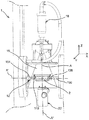
まず図1および2の両方を参照すると、低エネルギー電子衝撃によって物体2を殺菌するための装置1を見ることができ、該装置1は特に、略直方体形状を有する物体を処理するためのものとされている。
Referring first to both FIGS. 1 and 2, an
上述したように、この形状は特に、例えば1つのタブにつき100個とされる多数のエレメントを含むタブの形状に相当しており、該エレメントは、医療用注射器のように好ましくは化学的に予備殺菌されている。 As mentioned above, this shape corresponds in particular to the shape of a tab comprising a large number of elements, for example 100 per tab, which elements are preferably preliminarily chemically preliminarily like medical syringes. Sterilized.
装置1は、水平平面として特徴付けされうるフロア4に配置されている。したがって、当該説明は、互いに直角の方向X、YおよびZであって、グラウンド4に平行であるとともに装置内における物体の前方移動の方向に一致する方向Xと、装置の横方向に一致するとともにグラウンド4に平行な方向Yと、前記グラウンド4に対して直角である高さの方向に一致する方向Zと、を参照してなされていることに留意されたい。
The
一般に、装置は、以下のエレメントを備えており、該エレメントは、入口コンベア6と、入口エレベータ8と、入口ロック10と、物体2を移動させるための第1の機械式モジュール12と、オゾン排出パイプ14と、「焼成トンネル(firing tunnel)」とも呼ばれる処理チャンバ16と、ケーシング20の内側に配置された殺菌手段18と、物体2を移動させるための第2の機械式モジュール22と、出口ロック24と、出口エレベータ26と、出口コンベア28と、その内部に殺菌された物体2が送出される製品アイソレータ30とである。
In general, the apparatus comprises the following elements, which include an inlet conveyor 6, an inlet elevator 8, an
入口コンベア6は、処理される物体2を実質的に方向Xに移動させるホイール付き重力コンベアである。それは、下方部分にゲート32を備えており、該ゲート32は、電磁石(図示せず)によって、あるいは当業者に周知の他のタイプのアクチュエータによって制御され、物体2が1つずつ解放されることを可能にして、それらが連続してかつ自動的に重力によって入口エレベータ8に入るようにする。図1に見られるように、入口コンベア6の端部分は、好ましくはステンレス鋼からなる保護壁によって取り囲まれており、該壁は、入口エレベータ8の下方部分に延びている。
The entrance conveyor 6 is a wheeled gravity conveyor that moves the
入口エレベータ8はまた、その上方部分に保護二重壁を備えており、該保護二重壁は、ステンレス鋼の不浸透性コーティングと、好ましくは鉛からなるシールドコーティングとを備えている。装置1における他のシールドされたエレメントに関して、エレベータ8を取り囲むシールドコーティングは、主に、処理中の殺菌手段18によって放出される電子ビームからの全体の生物学的保護部を提供するように機能する。
The inlet elevator 8 is also provided with a protective double wall in its upper part, which is provided with a stainless steel impervious coating and a shield coating, preferably made of lead. With respect to the other shielded elements in the
加えて、エレベータ8は、コンベア6からの物体2のためのキャリアとして機能するシールド可動プレート34を有しており、該プレート34は、方向Zに移動されることができる。その下方位置において、プレート34が実質的に入口コンベア6における方向Xでの延長部に配置されていることに留意されたい。
In addition, the elevator 8 has a shield
方向Zにおけるエレベータ8、つまり上方側へのエレベータ8の右側は、入口ロック10であり、該入口ロック10は、方向Xに隣接する処理チャンバ16の方へ開口した平行六面体ボックスの形をなす保護二重壁によって画成されている。この保護二重壁はまた、不浸透性のステンレス鋼と、15mmのオーダーの厚みを有する、好ましくは鉛からなるシールドコーティングとを備えている。
The elevator 8 in the direction Z, ie the right side of the elevator 8 in the upward direction, is an
第1の機械式モジュール12は、前記ボックスの外面YZに、つまり、方向YおよびZによって規定される平面内に方向付けられた外面YZに固定的に取り付けられている一方、オゾン排出パイプ14は、この同一のボックスの上の面XYに、つまり、方向XおよびZによって規定された平面内に方向付けられた面XYに取り付けられている。この点に関しては、シールドプレート34が、その上方位置において上述した保護ボックスの下面XYを構成するように意図されており、該保護ボックスは、内側における面YZが自発的に省略されて、入口ロック10と隣接する処理チャンバ16との間の連通を許容していることを明記しておく。したがって、プレート34は、その位置に応じて、上述の生物学的保護部を備えた入口ロック10の開閉を確実に行うことができる。
The first
処理チャンバ16は、方向Xにおける入口ロック10の延長部に配置され、そしてまた、この同一の方向Xにおける両側で開口した略平行六面体ボックスの形をなす保護二重壁によって画成されている。ここで再び、保護二重壁は、ステンレス鋼の不浸透性コーティングと、15mmのオーダーの厚みを有する、好ましくは鉛からなるシールドコーティングとを備えている。それにもかかわらず、このボックスの上面XY、つまり、方向XおよびYによって規定される平面内に方向付けられた上面XYは、殺菌手段18が配置される1つの不浸透性コーティングのみを有していることに留意されたい。これらの手段はまた、シールドケーシング20の内側に配置されており、該シールドケーシング20は、約15mmの厚みの鉛からなり、かつ、処理チャンバ16を画成する前述のボックスよりも上に配置されている。
The
軸線Aに沿った低エネルギー電子ビームを発生させることができる殺菌手段18は、400KeVよりも下のエネルギーレベルを有する、例えば200のKeVのオーダーとされる、好ましくは電子銃あるいは加速器の形態をなしている。この銃18はしたがって、処理チャンバ16の縁部に、好ましくは図2に明確に見られるように方向Zで隣接して、装置1に固定的に取り付けられている。したがって、それらは、処理チャンバ6を通過するとともに方向Zと平行に方向付けられた軸線Aに沿って、電子ビームを放出することができる。加えて、これらの殺菌手段18は、周知の様式で、銃の端部に電子ビームスキャニングホーン(図示せず)を含んでおり、該電子ビームスキャニングホーンは、電子のための出口窓を画成し、方向Xにしたがうように方向付けられている。
The sterilization means 18 capable of generating a low energy electron beam along the axis A has an energy level below 400 KeV, for example in the order of 200 KeV, preferably in the form of an electron gun or accelerator. ing. This
第2の機械式モジュール22は、以下で詳細に説明されるように、前述したボックスの内側で面XYに取り付けられている。
The second
出口ロック24は、方向Xにおける処理チャンバ16の延長部に配置され、そしてまた、処理チャンバ16の方へ開口した平行六面体ボックスの形をなす保護二重壁によって画成されている。この保護二重壁は、ステンレス鋼の不浸透性コーティングと、15mmのオーダーの厚みを有する好ましくは鉛からなるシールドコーティングとを備えている。
The
方向Zとは反対方向における出口ロック24、つまり下方側への出口ロック24の右側は、出口エレベータ26であり、該出口エレベータはまた、その上方部分に保護二重壁を備え、該保護二重壁は、ステンレス鋼の不浸透性コーティングと、好ましくは鉛からなるシールドコーティングとを備えている。
The
加えて、エレベータ26は、出口ロック24からの物体2のためのキャリアとして機能するシールド可動プレート36を有しており、該プレート36は、方向Zに移動されることができる。この点に関しては、シールドプレート36が、その上方位置において出口ロック24を画成する保護ボックスの下面XYを構成するように意図されており、該出口ロックは、内側における面YZが自発的に省略されて、入口ロック24と隣接する処理チャンバ16との間の連通を許容していることを明記しておく。したがって、プレート36は、その位置に応じて、出口ロック24の開閉を確実に行うことができる。
In addition, the
加えて、その下方位置において、プレート36が実質的に出口コンベア28における方向Xでの延長部に配置されていることに留意されたい。入口コンベア6と同様に、出口コンベア28は、処理される物体2を実質的に方向Xに移動させるホイール付き重力コンベアである。図1に見られるように、出口コンベアの最初の部分は、好ましくはステンレス鋼からなる保護壁によって取り囲まれており、該壁は、出口エレベータ26の下方部分に延びている。
In addition, it should be noted that in its lower position, the
最後に、出口コンベア28が製品アイソレータ30につながっていることに留意されたい。
Finally, note that the
以下、図3および4を参照して、第1の機械式モジュール12を説明する。
Hereinafter, the first
一般に、この第1の機械式モジュール12は、処理される物体2を把持するための手段38、40と、方向Xに方向付けられた軸線A’にしたがって、それゆえ軸線Aに対して直角の軸線A’にしたがって前記物体2を装置1の内側において並進させて移動させるように意図された第1の移動手段42と、前記物体2を装置1の内側において前記同一の軸線A’まわりに回転させて移動させるように意図された第2の移動手段と、を備えている。これらの第2の手段は、図1および2のみに示されており、それらが符号44で示されていることに留意されたい。実際には、これらの第2の手段44は、ドライブピニオン46と軸線A’にその軸線が結合されたギアアセンブリ48とによって、図3に示されるすべてのアセンブリを回転させるように意図されており、該ドライブピニオンおよびギアアセンブリは、ロック10、26と処理チャンバ16とによって共同で形成されたシールド筐体に対して外部に取り付けられている。加えて、図1も参照すると、第1のモジュール12は、円形横断面を有したケーシングの形をなす不浸透性のシールドされた保護二重壁49を備えており、その中には図3に示されるアセンブリが挿入されている。
In general, this first
把持手段は、平面YZ内に実質的にしたがって方向付けられた2つの平行な把持面38および40を有しており、そのそれぞれが、図4に見られるように、物体2の周縁部47に係合するために方向Xに延びる歯49を備えている。処理される物体2を軸線A’まわりのその回転中に把持手段が保持するように意図されているならば、これらの歯49はもちろん、前述した周縁部46の上および下に配置されるように分散される。
The gripping means has two parallel
面38は、第1の機械式モジュール12の主アーム50の端部に配置されており、方向Xに延びるアーム50は、明瞭さの分かりきった理由のために1つのみが図3に示された2つの平行のトラック53に沿って、この同一方向にスライドするように意図されている。加えて、最外面40は、第1の機械式モジュール12の副アーム54の端部に配置されたフレーム52に属しており、該フレーム52は、物体2を方向Zに通過させることが可能な十ように分に大きいサイズを有している。加えて、アーム54はまた、方向Xに延びており、そして、主アーム50に対して、好ましくはその上に配置されて、方向Xにスライドするように意図されている。このオプションは、ドライブピニオン58によって制御される副アーム54上のラック56の存在によって提供される。したがって、このドライブピニオン58を作動させることにより、2つの把持面38、40の間の方向Xにおける距離を制御することが可能であり、主として、保持される物体2のサイズに関するこの上記距離を調節する。
The
前記図3も参照すると、副アーム54を支持する主アーム50のスライドが可能なように意図された第1の移動手段42は、この同一のアーム50に配置されたドライブピニオン60およびラック62を含んでいる。
Referring also to FIG. 3, the first moving means 42 intended to allow the
第1の機械式モジュール12のドライブピニオン46に関しては、このモジュールのモータとドライブピニオン58および60とが、図1および2に見られるように、装置のシールドの外側に配置されている。
With respect to the
図5を参照して、第2の機械式モジュール22を説明する。
The second
一般に、この第2の機械式モジュール22は、処理される物体2を支持するための手段64と、方向Zに方向付けられるとともに好ましくは電子ビームの軸線Aに結合された軸線A”のまわりに、物体2を装置1の内側において回転させて移動させるように意図された第3の移動手段66と、物体2を装置1の内側において前記軸線A”にしたがって並進させて移動させるように意図された第4の移動手段67と、を備えている。加えて、第2のモジュール22は、円形横断面を有したケーシングの形をなす不浸透性のシールドされた保護二重壁68を備えていることが図1に見受けられ、その中には図5に示されたアセンブリが挿入されている。
In general, this second
モジュール22は、軸線A”に沿って方向付けられたアーム70を有しており、その上方端部は、物体2が重力によって載置されることが可能なサポート手段64とされている。加えて、このアーム70は、このアーム70に対して機械的に接続されたギアアセンブリ72を含む第3の移動手段66に結合されており、該ギアアセンブリ72は、軸線A”と軸線を共有し、かつ、同じく第3の手段66に属するドライブピニオン74と協働している。好ましくは、エレメント72、74が、より詳しくは保護二重壁68によって保護された装置のシールドの外側に配置されている。
The
加えて、第4の移動手段67は、ドライブピニオン76を含み、そのモータはまた、保護二重壁68によって設けられたシールドの外側に設けられており、該ドライブピニオン76は、アーム70に直接形成されたラックと協働して、アーム70を方向Zにスライドさせることを許容する。
In addition, the fourth moving means 67 includes a drive pinion 76, the motor of which is also provided outside the shield provided by the protective
本発明の好ましい実施例による低エネルギー電子衝撃によって物体を殺菌するための方法を実行中の装置1の動作を説明する。
The operation of the
最初に、以下で示されるすべての動作は、適切なコンピュータ手段(図示せず)で自動化されることができるものであり、物体のそれぞれがコンベア6と製品アイソレータ30との間の全通路において完全に自動的に取り扱われる前には、殺菌される物体2をオペレーターが入口コンベア6に手動で配置する必要があるのみとできることに留意されたい。
Initially, all operations shown below can be automated with suitable computer means (not shown), each of the objects being completely in the entire path between the conveyor 6 and the
ゲート32の作動は、物体2を入口コンベア6から解放させ、該物体2はその後、重力によって、より詳しくは下方位置に保持されたプレート34上をスライドして、入口エレベータ8に自動的に入ることができる。
Actuation of the
それから、プレート34が入口ロック10を閉鎖する上方位置まで上昇し、前記プレート34によって支持された物体2が把持手段の2つの面38、40に侵入し、その分離が結果的に固定される。ドライブピニオン58および60は、面38、40が一緒に移動するように作動させられ、それらの歯49は、図4で符号80によって示されたいわゆる第2の面で、平行な平面YZ内に方向付けられた物体2の2つの対向する面の周縁部47にそれぞれ係合する。
The
この第2の面80は、したがって、軸線A’に関して直交して配置されており、好ましくは軸線A’が通過する。
This
それから、プレート34が、連続的な生物学的鉛保護を保証しつつ、わずかに下降され、そして、第1の移動手段42が、方向Xへの主アーム50の移動によって物体2を方向Xに並進させて処理チャンバ16の方へ移動させるように作動させられる。ドライブピニオン58が明らかに静止したままとなるようなこの移動を生じさせるドライブピニオン60は、平面XY内に方向付けられた物体2の上面に、好ましくは中央に、軸線A’が直交して通過したときに停止する。この上方のいわゆる第1の面は、図4で符号82によって示されている。
The
このとき、表面が電子衝撃によって処理される物体2は、図6aに概略的に示されるように、処理チャンバ16の内側に配置されている。エレベータ26のプレート36は、シールされない様式で出口ロック24を閉鎖するように上方位置にあり、前記ロックは、入口ロック10およびチャンバ16と共同で、電子ビームから全体の生物学的保護部を提供する、シールされていないシールド筐体を構成する。入口ロック10および出口ロック24のシールされない閉鎖は、空気が前述の筐体に供給されることを可能にし、これは、電子衝撃によって生成されるとともにパイプ14によって放出されるように意図されたオゾンを希釈するために役立つ。さらに、このシールされた閉鎖は、アイソレータ30の無菌保護部にとって有利な空気循環の案内につながる。
At this time, the
この段階で、殺菌手段18が、それから軸線Aに沿った前述の電子ビームを発生させるように実行され、前記ビームの焦点が固定されて実質的に第1の側面82の全面を照らすことができるか、あるいは、下方焦点によるビームのスキャニングが方向Xに作用させられる。実際には、この後者の場合、適用される振動周波数は、適用される回転速度で処理される物体の全面を照らすように、ビームにとって十分に高い。
At this stage, the sterilization means 18 is then executed to generate the aforementioned electron beam along the axis A so that the focus of the beam can be fixed to illuminate substantially the entire
同時に、第1の機械式モジュール12の第2の移動手段44が、ドライブピニオン46によって作動させられ、物体2を軸線A’まわりに回転させて移動させる。
At the same time, the second moving means 44 of the first
軸線A’まわりに物体2を回転させるこのフェーズは、固定電子ビームの軸線Aが物体2の面のうちの1つを連続的に通過している間、前記物体が完全に回転させられるまで適用される、つまり図3に示された第1の機械式モジュール12の全体が前記軸線A’まわりの360°回転を実行するまで、適用される。
This phase of rotating the
したがって、物体2を回転させるこの第1のフェーズ中、第1の面82を含む前記物体の6つの面のうちの4つが、低エネルギー電子衝撃によって処理されうる。加えて、これらの4つの面のそれぞれが、ビームの軸線Aに垂直にさらされることになる。
Thus, during this first phase of rotating the
当然、満足な処理を得るため、殺菌手段18の供給電流/電力を制御することが可能であり、この第1の回転フェーズの終わりにおいて、4つの面のそれぞれが略同一かつ均一のユニット照射量を有する。軸線A’まわりに物体2を回転させている間に電子ビームの電力を変化させたいという願望は、これらの面は殺菌手段18から実質的に長い距離で電子ビームにさらされるという事実により、もちろん動機付けされる。実際、例として、殺菌手段18のベース55と処理される物体2の外面との間の垂直距離は、回転中に、85mm〜215mmの間で変化することができる。代わりに、物体によって受け入れられる照射量はまた、処理される物体2の位置に対する殺菌手段18の位置を制御することによって調整されてもよいことに留意されたい。
Of course, in order to obtain a satisfactory treatment, it is possible to control the supply current / power of the sterilization means 18, and at the end of this first rotation phase, each of the four surfaces has a substantially identical and uniform unit dose. Have The desire to change the power of the electron beam while rotating the
第1の回転フェーズの後、物体2は、したがって、図6aに示すようにその最初の位置に戻る。このとき、第2の機械式モジュール22の第4の移動手段67が、サポート手段64を物体2の下面と接触するまで方向Zに移動させるように作動させられる。
After the first rotation phase, the
ドライブピニオン58および60は、それから、面38、40を互いに分離させるように作動させられ、そして、それらの歯49が物体2の周縁部47を解放する。この動作が一旦完了すると、物体2が第4の移動手段67によって方向Zに再び移動して、この同一の物体は、支障なく軸線Aまわりに回転することが可能なように、把持手段38、40およびフレーム52から十分に遠ざかる。
The drive pinions 58 and 60 are then actuated to separate the
実際には、第3の移動手段66が、前記軸線A”まわりに90°あるい270°とされる角度で物体2を回転させるために、ドライブピニオン74によって作動させられる。
In practice, the third moving means 66 is actuated by a
それから、第4の移動手段67が再び動かされて、物体2を把持手段38、40と協働可能な位置に下ろして戻し、該把持手段38、40がそれからまた互いの方へ向かって移動するように戻され、それらの歯49が物体2の他の2つの面の周縁部47にそれぞれ係合する。これが達成されると、ドライブピニオン76によってサポート手段64がそれらの当初の載置位置まで下方側へ移動され、それらが軸線A’まわりに回転する物体2に対する障害とならないようになる。
Then, the fourth moving means 67 is again moved down to bring the
図6bに見られるように、したがってそれは、第1および第2の面82、80に対して直角の2つの面のうちの1つであって軸線A’が直交して通過し、いわゆる第3の面が図6bにおいて符号84によって示されている。加えて、第1の面82は、平面XY内に方向付けられた上面のままとなっており、かつ、依然として電子ビームの軸線Aが直交して通過するようになっている。
As can be seen in FIG. 6b, it is therefore one of two planes perpendicular to the first and
第1の機械式モジュール12の第2の移動手段44は、ドライブピニオン46によって再び作動させられ、物体2を軸線A’まわりに回転させて移動させる。
The second moving means 44 of the first
軸線A’まわりに物体2を回転させるこの第2のフェーズは、固定電子ビームの軸線Aが物体2の面のうちの1つを連続的に通過している間、好ましくは前記物体が完全に回転するまで適用される。
This second phase of rotating the
したがって、軸線A’まわりに物体2を回転させるこの第2のフェーズ中に、前記物体の6つの面のうちの4つが、低エネルギー電子衝撃によって処理されることができ、該面は、第1の面80とそれに平行かつ反対側の面とを含み、該2つの面は、第1の回転フェーズ中に処理されなかった唯一のものである。
Thus, during this second phase of rotating the
ここで、再び、満足な処理を得るため、殺菌手段18の供給電流/電力を制御することが可能であり、この第2の回転フェーズの終わりにおいて、4つの面のそれぞれが略同一かつ均一のユニット照射量を有することに留意されたい。処理される物体2の位置に関して殺菌手段18の位置を制御できるという代替例もまた考慮することができる。目安として、第1の物体回転フェーズにおいて面のうちの2つが既に処理されると、これら2つの面の処理が第1の回転フェーズにおいて既に実行された処理に関する最小の相補的処理のみを構成するように、制御が実行されることができる。それにもかかわらず、当然、2つの回転フェーズのそれぞれの間に軸線Aが通過する2つの面の殺菌を確実に行うための他の解決法を考慮でき、例えば、前記2つの回転のそれぞれの間に処理の半分が提供される解決法、あるいは、これらの2つのフェーズのうちの1つの間に必要なすべての処理が提供される解決法を考慮できる。
Here again it is possible to control the supply current / power of the sterilization means 18 in order to obtain a satisfactory treatment, and at the end of this second rotation phase, each of the four surfaces is substantially identical and uniform. Note that it has a unit dose. An alternative where the position of the sterilization means 18 can be controlled with respect to the position of the
また、第2の回転フェーズのおわりに、殺菌手段によって物体2を照らす終わりをマーキングすると、物体は、第1の移動手段42によって方向Xに移動する前に、図面6bに示される位置に戻される。この並進は、物体2が出口ロック24に到達したときに停止され、出口エレベータ26のプレート36の右側にかつほとんど接触するようにして配置される。
Also, at the end of the second rotation phase, marking the end of illuminating the
ドライブピニオン58および60はそれから、面38、40が互いに分離するように作動させられ、それらの歯49が物体2の周縁部47を解放する。方向Zとは反対方向、つまり下方側にエレベータ24によって移動させられる物体2は、プレート36が下方位置に到達したときに停止され、該下方位置では、前記物体2が重力により、製品アイソレータ30へ物体を運び込む出口コンベア28に自動的に搬送される。
The drive pinions 58 and 60 are then actuated so that the
該方法は、好ましくは、処理される物体2がプレート36上に降ろされるフェーズ中に、前記物体2が、例えば入口エレベータ8で入口ロック10に移動させられることによって、装置1におけるそのコースを開始するように実行されることを明記しておく。
The method preferably starts its course in the
最後に、プレート34でロック10を閉鎖することにより、かつ、シールされたシールド筐体を通してアイソレータ30からの殺菌薬剤を循環させることにより、装置1の従来の殺菌が実行でき、該薬剤は、第1の機械式モジュール12のケーシング49の形をなす保護二重壁の自由端部に取り付けられた導管88と、パイプ14とを通して放出できることを示しておく。装置1を殺菌するこのフェーズ中、プレート34は、入口ロック10の開口部のまわりに設けられたシールジョイント(図示せず)を押圧することができる位置に移動され、求められるものとは違って、電子衝撃による物体2の殺菌中に、入口ロック10が密閉シールされることに留意されたい。装置1を殺菌する動作中、殺菌薬剤はそれから、アイソレータ30から入口ロック10まで移動する方向に循環される。
Finally, conventional sterilization of the
図7を参照すると、低エネルギー電子衝撃によって物体2を殺菌するための装置1を見ることができ、該装置1が、本発明の他の好ましい実施例で示されている。
Referring to FIG. 7, one can see an
上述した図面1〜6bに示された実施例に関するいくつかの違いが見受けられる。まず、殺菌手段18が、第1の機械式モジュール(符号を付けていない)により、軸線A’まわりに旋回可能に取り付けられているという事実に大きな相違点が存在していることに留意されたい。実際には、それは、低エネルギー電子衝撃処理中に、静止したままの物体2のまわりで軸線A’に関して回転する殺菌手段18である。
Several differences can be seen with respect to the embodiment shown in Figures 1-6b described above. First, it should be noted that there is a significant difference in the fact that the sterilizing means 18 is pivotally mounted about the axis A ′ by means of a first mechanical module (not labeled). . In practice, it is a sterilization means 18 that rotates about the axis A 'around the
加えて、この軸線A’は、物体2が装置1の内側で並進して移動するときにしたがうことができる軸線のままである。これは、2つの略同軸のアーム150、154によって達成され、そのそれぞれは、物体2の2つの対向する面YZにそれぞれ接触するように意図された把持面138、140を支持している。したがって、2つのアーム150、154はそれぞれ、上述の実施例に示されたものに類似する手段の補助により、方向Xにスライドすることができ、そして、それらのそれぞれは、装置の1つの側面に、例えば入口ロック10上および出口ロック24上のそれぞれに取り付けられている。
In addition, this axis A 'remains the axis that can be followed when the
加えて、図示されていないが、入口および出口エレベータを取り除くことができ、これは、入口および出口コンベア(図7に示されていない)が、直接的にかつ個々に、装置1の入口および出口ロック(図7に示されていない)につながっていることを意味する。そのような場合、これらのコンベアは、生物学的保護部を設けるようにバッフルを形成する。
In addition, although not shown, the inlet and outlet elevators can be removed because the inlet and outlet conveyors (not shown in FIG. 7) are directly and individually connected to the inlet and outlet of the
その上述した相違点のそれぞれは、本発明の範囲から逸脱することなく、図1〜6bに示された実施例の装置1に適用されることを明記しておく。
It is noted that each of the above-mentioned differences applies to the
もちろん、当業者により、単に非限定的な例として説明されてきた物体の殺菌のための装置1および方法に対して、様々な修正を施すことができる。
Of course, various modifications can be made by those skilled in the art to the
1 装置
2 物体
6 入口コンベア
8 エレベータ
10 入口ロック
12 第1の機械式モジュール
16 処理チャンバ
18 殺菌手段
22 第2の機械式モジュール
24 出口ロック
26 エレベータ
28 出口コンベア
30 製品アイソレータ
34 プレート
36 プレート
38 把持手段
40 把持手段
42 第1の移動手段
44 第2の移動手段
66 第3の移動手段
67 第4の移動手段
80 第2の面
82 第1の面
A 軸線
A’ 軸線
A” 軸線
X 方向
Y 方向
Z 方向
1
Claims (19)
該装置は、装置の処理チャンバ(16)を通過する軸線(A)に沿って低エネルギー電子ビームを発生させることができる殺菌手段(18)を含み、該装置はまた、処理チャンバ(16)の内側に配置された処理される物体(2)の殺菌中に、物体(2)と前記殺菌手段(18)との間の軸線(A’)まわりの第1及び第2の相対的回転移動を生じさせることができるように構成された第1の機械式モジュール(12)を含み、該軸線(A’)は、前記殺菌手段(18)によって発生される前記電子ビームの軸線(A)が、前記軸線(A’)まわりの前記第1及び第2の相対的回転移動の間に、物体(2)の外面を連続的に通過するように選択されており、
該装置は、前記第1の相対的回転の後かつ前記第2の相対的回転移動の前に前記処理チャンバ(16)の内側に配置された物体(2)が第1の機械式モジュール(12)から解放されたときに、軸線(A’)に関して直交して方向付けられた軸線(A”)まわりの物体(2)の回転を生じさせることができるように構成された第2の機械式モジュール(22)を備えていることを特徴とする装置。 In an apparatus (1) for sterilizing an object by low energy electron impact on the outer surface of the object,
The apparatus includes sterilization means (18) capable of generating a low energy electron beam along an axis (A) passing through the process chamber (16) of the apparatus, the apparatus also comprising a process chamber (16) During the sterilization of the object to be treated (2) arranged on the inside, the first and second relative rotational movements about the axis (A ′) between the object (2) and the sterilization means (18). A first mechanical module (12) configured to be able to be generated, the axis (A ′) being the axis (A) of the electron beam generated by the sterilizing means (18), Selected to continuously pass through the outer surface of the object (2) during the first and second relative rotational movements about the axis (A ′);
The apparatus includes an object (2) disposed inside the processing chamber (16) after the first relative rotation and before the second relative rotational movement, wherein a first mechanical module (12 A second mechanical type configured to cause rotation of the object (2) about an axis (A ″) oriented orthogonally with respect to the axis (A ′) when released from Device comprising a module (22).
前記第1の機械式モジュール(12)は、前記処理チャンバ(16)の内側に配置された処理される物体(2)の殺菌中に、前記物体(2)および前記殺菌手段(18)から選択された2つのエレメントのうちのいずれか1つと協働して、前記エレメントを前記軸線(A’)まわりに回転させるように制御されることを特徴とする装置。 In an apparatus (1) for sterilizing an object according to claim 1,
The first mechanical module (12) is selected from the object (2) and the sterilizing means (18) during the sterilization of the object to be processed (2) arranged inside the processing chamber (16) The apparatus is controlled to rotate the element about the axis (A ′) in cooperation with any one of the two elements.
処理される物体(2)が、第1の機械式モジュール(12)と協働して前記軸線(A’)まわりに回転して移動されるように意図されたエレメントを構成し、かつ、前記殺菌手段(18)が、装置に固定的に取り付けられていることを特徴とする装置。 In an apparatus (1) for sterilizing an object according to claim 1,
The object (2) to be treated constitutes an element intended to rotate and move about said axis (A ′) in cooperation with a first mechanical module (12), and Device, characterized in that the sterilizing means (18) is fixedly attached to the device.
略直方体形状を有する物体を殺菌するように意図されていることを特徴とする装置。 In an apparatus (1) for sterilizing an object according to claim 3,
A device intended to sterilize an object having a substantially rectangular parallelepiped shape.
前記第1の機械式モジュール(12)は、処理される物体(2)を把持するための手段(38、40)を備え、第1のモジュール(12)は、把持手段(38、40)と協働して前記物体(2)を処理チャンバ(16)内へ動かすように意図されて、この物体(2)の第1の面(82)が軸線(A)によって通過されるようにする第1の移動手段(42)を備え、第1の機械式モジュール(12)はまた、軸線(A)と物体(2)の第2の面(80)とに関して直交して方向付けられた軸線(A’)まわりに物体(2)および把持手段(38、40)を回転させるように構成された第2の移動手段(44)を含んでおり、
第2の機械式モジュール(44)は、処理チャンバ(16)の内側で把持手段(38、40)から解放された物体(2)を、軸線(A’)と前記第2の面(80)に垂直な物体(2)の面のうちのいずれか1つとに関して直交して方向付けられた軸線(A”)まわりに、90°回転させるように構成された第3の移動手段(66)を含んでいることを特徴とする装置。 In an apparatus (1) for sterilizing an object according to claim 4,
The first mechanical module (12) comprises means (38, 40) for gripping the object (2) to be processed, the first module (12) comprising gripping means (38, 40) and It is intended to cooperate to move the object (2) into the processing chamber (16) so that the first surface (82) of the object (2) is passed by the axis (A). 1 moving means (42), the first mechanical module (12) also has an axis oriented orthogonally with respect to the axis (A) and the second surface (80) of the object (2) ( A ′) comprising second moving means (44) configured to rotate the object (2) and the gripping means (38, 40) about,
The second mechanical module (44) moves the object (2) released from the gripping means (38, 40) inside the processing chamber (16) into the axis (A ') and the second surface (80). A third moving means (66) configured to rotate 90 ° around an axis (A ") oriented perpendicular to any one of the surfaces of the object (2) perpendicular to A device characterized by containing.
前記第2の機械式モジュール(22)は、前記物体(2)を軸線(A”)にしたがって並進させて移動させるように構成された第4の移動手段(67)を備え、第3の移動手段(66)によって生じる同一の前記軸線(A”)に関する90°のその回転の間に、前記把持手段(38、40)から遠ざけるようにすることを特徴とする装置。 In an apparatus (1) for sterilizing an object according to claim 5,
The second mechanical module (22) comprises fourth moving means (67) configured to translate and move the object (2) according to an axis (A "), and a third movement Device characterized in that it is kept away from the gripping means (38, 40) during its rotation of 90 ° with respect to the same axis (A ") produced by the means (66).
前記第1の機械式モジュール(12)は、その把持手段(38、40)が、第3の移動手段(66)によって90°回転されて移動された略直方体形状を有する物体(2)に再び係合するように構成されかつ制御され、前記物体(2)が、第2の移動手段(44)によって軸線(A’)まわりに回転して移動されるようにすることを特徴とする装置。 In an apparatus (1) for sterilizing an object according to claim 6,
The first mechanical module (12) is again applied to the object (2) having a substantially rectangular parallelepiped shape whose gripping means (38, 40) is rotated by 90 ° by the third moving means (66). Arranged and controlled to engage, the device (2) is rotated by the second moving means (44) around the axis (A ') and moved.
前記軸線(A”)は、装置の高さの方向(Z)に方向付けられ、前記軸線(A)は、装置内における物体の前方への移動の方向(X)に方向付けられ、該方向(X)および(Z)は、互いに直交していることを特徴とする装置。 In an apparatus (1) for sterilizing an object according to claim 7,
The axis (A ″) is oriented in the height direction (Z) of the device, and the axis (A) is oriented in the direction of forward movement (X) of the object in the device, the direction (X) and (Z) are orthogonal to each other.
前記軸線(A)も、装置の高さの方向(Z)に方向付けられていることを特徴とする装置。 In an apparatus (1) for sterilizing an object according to claim 8,
The device characterized in that the axis (A) is also oriented in the height direction (Z) of the device.
該装置は、入口ロック(10)および出口ロック(24)を含み、それらの間には両ロックに連通する前記処理チャンバ(16)を含み、処理チャンバ(16)と2つの入口および出口ロック(10、24)とが前記方向(X)において位置合わせされていることを特徴とする装置。 In an apparatus (1) for sterilizing an object according to claim 8 or 9,
The apparatus includes an inlet lock (10) and an outlet lock (24) between which the processing chamber (16) communicates with both locks, the processing chamber (16) and two inlet and outlet locks ( 10, 24) are aligned in the direction (X).
前記第1の移動手段(42)が、入口ロック(10)と処理チャンバ(16)との間、および、処理チャンバ(16)と出口ロック(24)との間で、把持手段(38、40)によって保持された物体(2)の方向(X)における並進移動を許容するように構成されていることを特徴とする装置。 In an apparatus (1) for sterilizing an object according to claim 10,
The first moving means (42) includes gripping means (38, 40) between the inlet lock (10) and the processing chamber (16) and between the processing chamber (16) and the outlet lock (24). ), Which is configured to allow translational movement of the object (2) in the direction (X).
閉鎖位置における2つの入口および出口ロック(10、24)と、前記処理チャンバ(16)とが、共同して、シールされていないシールド筐体を形成することを特徴とする装置。 In an apparatus (1) for sterilizing an object according to claim 10 or 11,
Apparatus characterized in that the two inlet and outlet locks (10, 24) in the closed position and the processing chamber (16) together form an unsealed shield housing.
2つの入口および出口ロック(10、24)のそれぞれが、方向(Z)に方向付けられたエレベータ(8、26)と関連していることを特徴とする装置。 In an apparatus (1) for sterilizing an object according to any of claims 10-12,
Apparatus characterized in that each of the two inlet and outlet locks (10, 24) is associated with an elevator (8, 26) oriented in the direction (Z).
2つのエレベータ(8、26)のそれぞれが、物体(2)のためのキャリアとして機能するシールドされた可動プレート(34、36)を備え、該プレート(34、36)は、それが関連するロック(10、24)の閉鎖を保証するように構成されていることを特徴とする装置。 In an apparatus (1) for sterilizing an object according to claim 13,
Each of the two elevators (8, 26) comprises a shielded movable plate (34, 36) that functions as a carrier for the object (2), which plate (34, 36) is associated with the lock to which it is associated. Device configured to ensure closure of (10, 24).
2つのエレベータ(8、26)は、それぞれ前記物体を移動させることができる入口コンベア(6)および出口コンベア(28)とそれぞれ協働することを特徴とする装置。 In an apparatus (1) for sterilizing an object according to claim 13 or 14,
Two elevators (8, 26), each cooperating with an entrance conveyor (6) and an exit conveyor (28), respectively, capable of moving said object.
前記出口コンベア(28)は、殺菌された物体が送出される製品アイソレータ(30)につながっていることを特徴とする装置。 In an apparatus (1) for sterilizing an object according to claim 15,
The device characterized in that the outlet conveyor (28) is connected to a product isolator (30) through which sterilized objects are delivered.
前記第1の機械式モジュール(12)は、前記入口ロック(10)に固定的に取り付けられていることを特徴とする装置。 In an apparatus (1) for sterilizing an object according to any of claims 10 to 16,
The device according to claim 1, characterized in that the first mechanical module (12) is fixedly attached to the inlet lock (10).
低エネルギー電子ビームを発生させることのできる殺菌手段(18)が、前記処理チャンバ(16)の周囲に取り付けられた電子銃の形をとっていることを特徴とする装置。 In an apparatus (1) for sterilizing an object according to any of claims 1 to 17,
A device characterized in that the sterilization means (18) capable of generating a low energy electron beam take the form of an electron gun mounted around the processing chamber (16).
請求項1〜18のいずれかに記載の装置(1)を使用して実行されることを特徴とする方法。 In a method for sterilizing an object by low energy electron impact on the outer surface of the object,
A method characterized in that it is carried out using an apparatus (1) according to any of the preceding claims.
Applications Claiming Priority (2)
| Application Number | Priority Date | Filing Date | Title |
|---|---|---|---|
| FR0550287A FR2881351B1 (en) | 2005-02-01 | 2005-02-01 | INSTALLATION AND METHOD FOR STERILIZING OBJECTS BY LOW ENERGY ELECTRON BOMBING |
| FR0550287 | 2005-02-01 |
Publications (2)
| Publication Number | Publication Date |
|---|---|
| JP2006212434A JP2006212434A (en) | 2006-08-17 |
| JP4732910B2 true JP4732910B2 (en) | 2011-07-27 |
Family
ID=34954675
Family Applications (1)
| Application Number | Title | Priority Date | Filing Date |
|---|---|---|---|
| JP2006023295A Expired - Fee Related JP4732910B2 (en) | 2005-02-01 | 2006-01-31 | Apparatus and method for sterilizing objects by low energy electron impact |
Country Status (8)
| Country | Link |
|---|---|
| US (1) | US7459706B2 (en) |
| EP (1) | EP1685853B1 (en) |
| JP (1) | JP4732910B2 (en) |
| AT (1) | ATE430588T1 (en) |
| CA (1) | CA2534310C (en) |
| DE (1) | DE602006006606D1 (en) |
| FR (1) | FR2881351B1 (en) |
| PL (1) | PL1685853T3 (en) |
Families Citing this family (14)
| Publication number | Priority date | Publication date | Assignee | Title |
|---|---|---|---|---|
| FR2881351B1 (en) | 2005-02-01 | 2009-01-16 | Linac Technologies Sas Soc Par | INSTALLATION AND METHOD FOR STERILIZING OBJECTS BY LOW ENERGY ELECTRON BOMBING |
| FR2884426B1 (en) * | 2005-04-19 | 2009-11-06 | Linac Technologies Sas Soc Par | INSTALLATION FOR THE STERILIZATION OF OBJECTS BY ELECTRON BOMBING. |
| CN100467068C (en) * | 2005-07-29 | 2009-03-11 | 清华大学 | A shielded electron beam irradiation sterilization device |
| CN101108254B (en) * | 2006-07-17 | 2010-08-25 | 清华大学 | Mobile electron beam irradiation sterilization equipment |
| DK2094313T3 (en) | 2006-11-08 | 2012-08-20 | Skan Ag | Plants for sterilizing objects by means of radiation source |
| EP1982920A1 (en) * | 2007-04-19 | 2008-10-22 | Krones AG | Device for sterilising containers |
| ITUD20070155A1 (en) * | 2007-09-04 | 2009-03-05 | Internat Steel Co S P A | WASHING SYSTEM |
| FR2988612B1 (en) * | 2012-04-02 | 2014-08-08 | Getinge La Calhene | ELECTRON BOMBARDING STERILIZATION SYSTEM WITH REDUCED SIZE |
| WO2013154782A1 (en) * | 2012-04-12 | 2013-10-17 | Electronworks Holdings Llc | Low energy electron sterilization |
| JP5934577B2 (en) * | 2012-05-21 | 2016-06-15 | 株式会社エアレックス | Electron beam irradiation device |
| JP6543092B2 (en) * | 2015-05-27 | 2019-07-10 | 株式会社エアレックス | Electron beam irradiation device |
| ES2981276T3 (en) * | 2018-02-20 | 2024-10-08 | Buehler Ag | Device and method for pasteurizing and/or sterilizing products in particulate form |
| EP4424330A1 (en) | 2023-03-02 | 2024-09-04 | SKAN Stein AG | Method for serially transferring containers through a process chamber for further processing in a containment under aseptic conditions and production system therefor |
| EP4663209A1 (en) | 2024-06-10 | 2025-12-17 | SKAN Stein AG | Method for serially transferring objects through a process chamber for further processing in a containment under aseptic conditions and production system therefor |
Family Cites Families (12)
| Publication number | Priority date | Publication date | Assignee | Title |
|---|---|---|---|---|
| US4599216A (en) * | 1983-11-21 | 1986-07-08 | Board Of Regents For The University Of Oklahoma | Apparatus for exposure to microwaves |
| US5252290A (en) * | 1989-11-30 | 1993-10-12 | Jun Uesugi | Process for treatment and disposal of medical waste materials |
| JP3793797B2 (en) * | 1997-03-27 | 2006-07-05 | 岩崎電気株式会社 | Electron beam irradiation device |
| JP3775451B2 (en) * | 1997-03-31 | 2006-05-17 | 株式会社日立メディコ | Radiation irradiation device for blood bag |
| AT407311B (en) * | 1998-02-05 | 2001-02-26 | Mediscan Gmbh | METHOD FOR IRRADIATING A GOOD |
| JP2001249200A (en) * | 2000-03-02 | 2001-09-14 | Nkk Plant Engineering Corp | X-ray/electron beam rotary type irradiating device and method therefor |
| EP1189018B1 (en) * | 2000-09-15 | 2009-02-25 | Vistec Electron Beam GmbH | Six axes positioning system with a space free from magnetic field |
| US7183563B2 (en) * | 2000-12-13 | 2007-02-27 | Advanced Electron Beams, Inc. | Irradiation apparatus |
| JP2002221598A (en) * | 2001-01-26 | 2002-08-09 | Mitsubishi Electric Corp | Electron beam irradiation system and X-ray irradiation system |
| US6696018B2 (en) * | 2001-11-14 | 2004-02-24 | Electron Process Company, Llc | System and method for sterilization of biological connections |
| US7212017B2 (en) * | 2003-12-25 | 2007-05-01 | Ebara Corporation | Electron beam apparatus with detailed observation function and sample inspecting and observing method using electron beam apparatus |
| FR2881351B1 (en) | 2005-02-01 | 2009-01-16 | Linac Technologies Sas Soc Par | INSTALLATION AND METHOD FOR STERILIZING OBJECTS BY LOW ENERGY ELECTRON BOMBING |
-
2005
- 2005-02-01 FR FR0550287A patent/FR2881351B1/en not_active Expired - Fee Related
-
2006
- 2006-01-27 DE DE602006006606T patent/DE602006006606D1/en not_active Expired - Lifetime
- 2006-01-27 PL PL06100965T patent/PL1685853T3/en unknown
- 2006-01-27 EP EP06100965A patent/EP1685853B1/en not_active Expired - Lifetime
- 2006-01-27 AT AT06100965T patent/ATE430588T1/en not_active IP Right Cessation
- 2006-01-30 CA CA2534310A patent/CA2534310C/en not_active Expired - Fee Related
- 2006-01-31 JP JP2006023295A patent/JP4732910B2/en not_active Expired - Fee Related
- 2006-01-31 US US11/342,712 patent/US7459706B2/en not_active Expired - Fee Related
Also Published As
| Publication number | Publication date |
|---|---|
| ATE430588T1 (en) | 2009-05-15 |
| FR2881351B1 (en) | 2009-01-16 |
| PL1685853T3 (en) | 2009-09-30 |
| CA2534310C (en) | 2014-03-11 |
| EP1685853A1 (en) | 2006-08-02 |
| US7459706B2 (en) | 2008-12-02 |
| US20060186350A1 (en) | 2006-08-24 |
| CA2534310A1 (en) | 2006-08-01 |
| EP1685853B1 (en) | 2009-05-06 |
| DE602006006606D1 (en) | 2009-06-18 |
| FR2881351A1 (en) | 2006-08-04 |
| JP2006212434A (en) | 2006-08-17 |
Similar Documents
| Publication | Publication Date | Title |
|---|---|---|
| JP4732910B2 (en) | Apparatus and method for sterilizing objects by low energy electron impact | |
| KR102361931B1 (en) | electron beam irradiation device | |
| JP5490651B2 (en) | Neutron beam irradiation system | |
| EP2100814B1 (en) | Container sterilization apparatus | |
| JP6100696B2 (en) | Continuous sterilizer | |
| US9180216B2 (en) | Electron beam irradiation device with gripping/moving means | |
| JP2007516775A5 (en) | ||
| US20150071818A1 (en) | Apparatus and method for sterilizing containers | |
| JP6313544B2 (en) | Apparatus and method for radiation-based disinfection of container lids | |
| WO2007046213A1 (en) | Electron beam application method, electron beam application device, electron beam application device for opening-equipped vessel | |
| US20210275709A1 (en) | Arrangement for the Contamination-Free Introduction of a Sterile Object from a Container into a Containment and Method Therefor | |
| EP1478408B1 (en) | Apparatus and process for irradiating product pallets | |
| US20070176116A1 (en) | Self-shielded sterilization apparatus using electron beam irradiation | |
| JP2004236806A (en) | Electron beam sterilizer for exterior package of container | |
| JP2019217011A (en) | Decontamination pass box | |
| JP2003121597A (en) | Electron beam irradiation apparatus | |
| JP2004191307A (en) | Electron beam irradiation device | |
| JP3699686B2 (en) | Target transfer device | |
| KR20250037710A (en) | Electron beam integration for sterilizing radioactive agents inside hot cells | |
| JP2007287546A (en) | Vacuum container and electron beam device | |
| JP3141361B2 (en) | Electron beam irradiator and sheet-like object passing method | |
| WO2019244501A1 (en) | Bacteria treatment mechanism and bacteria treatment method | |
| JPH11168070A (en) | Treatment equipment provided with treatment vessel having direct-acting mechanism |
Legal Events
| Date | Code | Title | Description |
|---|---|---|---|
| A621 | Written request for application examination |
Free format text: JAPANESE INTERMEDIATE CODE: A621 Effective date: 20081217 |
|
| A977 | Report on retrieval |
Free format text: JAPANESE INTERMEDIATE CODE: A971007 Effective date: 20101111 |
|
| A131 | Notification of reasons for refusal |
Free format text: JAPANESE INTERMEDIATE CODE: A131 Effective date: 20101116 |
|
| A521 | Request for written amendment filed |
Free format text: JAPANESE INTERMEDIATE CODE: A523 Effective date: 20110216 |
|
| A01 | Written decision to grant a patent or to grant a registration (utility model) |
Free format text: JAPANESE INTERMEDIATE CODE: A01 Effective date: 20110405 |
|
| A01 | Written decision to grant a patent or to grant a registration (utility model) |
Free format text: JAPANESE INTERMEDIATE CODE: A01 |
|
| A61 | First payment of annual fees (during grant procedure) |
Free format text: JAPANESE INTERMEDIATE CODE: A61 Effective date: 20110421 |
|
| FPAY | Renewal fee payment (event date is renewal date of database) |
Free format text: PAYMENT UNTIL: 20140428 Year of fee payment: 3 |
|
| R150 | Certificate of patent or registration of utility model |
Free format text: JAPANESE INTERMEDIATE CODE: R150 |
|
| R250 | Receipt of annual fees |
Free format text: JAPANESE INTERMEDIATE CODE: R250 |
|
| LAPS | Cancellation because of no payment of annual fees |